Unit – 2
Software Requirements Engineering
Q1) Explain requirement analysis?
A1) Requirement Analysis
Requirement Analysis, also known as Requirement Engineering, is the process of defining user expectations for a new software being built or modified. In software engineering, it is sometimes referred to loosely by names such as requirements gathering or requirements capturing.
Requirement’s analysis encompasses those tasks that go into determining the needs or conditions to meet for a new or altered product or project, taking account of the possibly conflicting requirements of the various stakeholders, analyzing, documenting, validating and managing software or system requirements.
Activities for Requirement Analysis
Requirement’s analysis is critical to the success or failure of a systems or software project. The requirements should be documented, actionable, measurable, testable, traceable, related to identified business needs or opportunities, and defined to a level of detail sufficient for system design. Conceptually, requirements analysis includes four types of activity:
Q2) What are the functional requirements?
A2) Functional requirements
A functional requirement in software engineering determines a device or component. It defines the functions that must be performed by a programme. Nothing but inputs, their actions, and outputs are a function. It can be a calculation, data manipulation, business method, user interaction, or some other particular feature that determines what is likely to perform a system's purpose.
Requirements for usable applications allow you to capture the system's expected actions. This conduct may be represented in the form of functions, facilities or tasks or which system must be executed.
Example of functional requirements:
Some examples of non-functional specifications are available here:
● Only workers at the managerial level have the right to access revenue data.
● It is important to integrate the software framework with the banking API.
● Automatically, the programme validates clients against the ABC Contact Management System
● The Sales System should allow users to record sales of customers
Advantages of functional requirement
● Helps you to check if all the functionalities specified in the functional requirement of that application are given by the application.
● A document of functional specifications allows you to identify a system's functionality or one of its subsystems.
● Functional specifications help to define missing requirements along with requirement review. They help describe the intended service and behaviour of the system clearly.
● Errors caught in the collection stage of the Practical Requirement are the cheapest to repair.
Q3) What are non-functional requirements?
A3) Non - functional requirements
The quality attribute of a software system is specified by a non-functional requirement. They reflect a collection of criteria that are used to judge a system's basic activity. How quick, for example, does the website load?
To ensure the usability and efficacy of the entire software framework, a non-functional requirement is vital. Failure to meet non-functional specifications will lead to systems that do not meet the needs of users.
Non-functional specifications allow you to enforce system design restrictions or limitations through the various agile backlogs. For e.g., if the number of simultaneous users is > 10000, the site should be loaded within 3 seconds. It is just as important as a functional requirement to define non-functional requirements.
Example of non - functional requirements:
Some examples of non-functional specifications are available here:
● Users must, immediately after the first successful login, adjust the initially assigned login password. In addition, the original can never be reused.
● Any failed attempt by a user to access a data item must be registered on the audit trail.
● A website should be able to manage the effect of 20 million users on its results.
● The device needs to be portable. Therefore, switching from one OS to another OS causes no problem.
Advantages of non - functional requirements
Non-functional testing's benefits/pros are:
● The non-functional specifications ensure that legal and regulatory laws are observed by the software system.
● They guarantee the reliability, usability and productivity of the software system.
● They guarantee good user experience and ease of software activity.
● They help to formulate the information system security strategy,
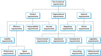
Fig 1: non - functional requirement
Q4) Describe Software Requirement Specification (SRS)?
A4) Software Requirement Specification (SRS)
A specification of software requirements (SRS) is a document that explains what the software is supposed to do and how it is expected to work. It also describes the functionality needed by the product to fulfil the needs of all stakeholders (business, users)
A Software Specifications Specification (SRS) is a document that provides a complete overview of the anticipated performance of the device. It is normally signed off at the conclusion of the engineering process of the specifications.
A standard SRS consists of -
● A purpose - Initially, the main objective is to clarify and illustrate why this document is important and what the intention of the document is.
● An overall description - The product summary is explained here. It's simply a rundown or an overall product analysis.
● Scope of this document - This outline and demonstrates the overall work and primary goal of the paper and what value it can bring to the consumer. It also provides a summary of the cost of construction and the necessary time.
When embedded in hardware, or when linked to other software, the best SRS documents describe how the software can communicate.
Some of the attractive qualities of an SRS are
1. Correct
2. Complete
3. Unambiguous
4. Verifiable
5. Consistent
6. Ranked for importance and/or stability
If there is any cost-effective mechanism that can verify if the final software meets the requirement, the requirement is verifiable.
Of all these characteristics, completeness is probably the most essential property to create and also the most difficult. Incompleteness is one of the most common shortcomings in design specifications. Missing specifications require additions and adjustments to the specifications later in the development cycle, which are also costly to implement. Incompleteness is also a significant cause of the customer's disagreement with the supplier.
Q5) What are the components of srs?
A5) Components of an SRS
Some of the device properties that an SRS can define are listed here.
1. Functional requirements
The functional requirements specify what output from the given inputs should be generated. So, they simply define the connectivity between the system's input and output. For each practical demand:
2. Performance requirements
The performance restrictions on the software system are defined in this section of the SRS. It is important to clearly define all specifications relating to the performance characteristics of the system. For a user event or screen refresh time or a mix of both, performance criteria are usually expressed as processed transactions per second or response time from the device. It is a good idea for the most used or important transactions, user events and screens to pin down performance criteria.
3. Design constraints
The client environment can prohibit the designer from including some design constraints that need to be met. Standard enforcement, resource limitations, operating environment, reliability and security specifications and policies that could have an impact on the system design are the various design constraints. All such constraints should be defined and specified by an SRS.
● Standards compliance: This defines the specifications for the standard to be adopted by the framework. The criteria which include the format of the report and the respective procedures.
● Hardware imitations: To run, the programme requires some current or predetermined hardware, thus enforcing design restrictions. Hardware limitations which include the types of machines used to provide memory space for the operating system, etc.
● Fault tolerance: The criteria for fault tolerance will impose a significant restriction on the design of the device. Requirements for fault tolerance often make the system more complicated and costly, so they should be reduced.
● Security: Security specifications for all types of systems have become important and relevant at the moment. Security standards limit the use of certain commands to manage access to the database, provide various forms of access, require different individuals to access, require the use of passwords and cryptography techniques, and retain a device log of activities.
4. External interface requirements
For the specifications of each external interface:
Q6) What are IEEE 830 guidelines?
A6) IEEE 830 guidelines
Software engineering standards and related documents have been established by the IEEE, ISO, and other standards organizations. A software engineering company may adopt standards willingly or be forced to do so by the customer or other stakeholders. SQA's role is to make sure that the guidelines that have been established are followed and that all work items are compliant with them.
SRS creation is a joint effort that begins with the design of a software project and ends with the conversion of the SRS text. A basic structure and components for SRS have been proposed by several organizations. The IEEE has laid out a basic framework for software creation.
An example of a simple SRS outline is as follows:
Introduction -
● purpose
● Document convention
● Intended audiences
● References
● Additional information
Overall description -
● Product perspective
● Product function
● User environment
● Design
● Assumptions & depended
External interface requirement -
● User interface
● Hardware interface
● Software interface
● Communication protocols and interfaces
System features -
● Description and priority
● Action/result
● Functional requirements
Q7) Explain the decision table and tree?
A7) Decision table and tree
A decision table is a quick visual representation of certain actions to take in response to certain conditions. The knowledge in decision tables may also be interpreted as decision trees or as if-then-else and switch-case statements in a programming language.
A decision table, also known as a cause-effect table, is a good way to settle for various combinations of inputs and outputs. The cause-effect table is named after a similar logical diagramming method known as cause-effect graphing, which is primarily used to generate the decision table.
Decision Table: Combinations
CONDITIONS STEP 1 STEP 2 STEP 3 STEP 4
Condition 1 Y Y N N
Condition 2 Y N Y N
Condition 3 Y N N Y
Condition 4 N Y Y N
Importance of decision table:
● In terms of test design, decision tables are extremely useful.
● It assists testers in determining the effects of various inputs and other software states that must correctly apply business rules.
● When dealing with complex business codes, it is a systematic exercise to plan specifications.
● It's also used to simulate complex logic.
● A decision table is a fantastic tool that can be used in both research and requirements management.
Advantages
● Using this technique, any dynamic business flow can be easily translated into test scenarios and test cases.
● It provides comprehensive coverage of test cases, reducing the amount of time spent rewriting test scenarios and test cases.
● These tables ensure that we take into account all possible combinations of condition values. This is referred to as the property of completeness.
● This approach is easy to understand, and anyone can use it to build test scenarios and test cases.
Q8) Describe cohesion?
A8) Cohesion
A good software design implies clean decomposition of the problem into modules and the neat arrangement of these modules in a hierarchy. The primary characteristics of neat module decomposition are low coupling and high cohesion.
Cohesion is a measure of functional strength of a module. A module having low coupling and high cohesion is said to be functionally independent of other modules. Functional independence means that a cohesive module performs a single function or task. A functionally independent module has very little interaction with other modules.
Types of Cohesion
The different classes of cohesion that a module may possess are shown:

Fig 2: classification of cohesion
● Coincidental Cohesion: A module is said to have coincidental cohesion if it performs a set of functions or tasks that relate to each other very loosely. In this case, the module contains a random collection of functions. It is likely that the functions have been put in the module out of pure coincidence without any design or thought. For example, in a transaction processing system (TPS), the get-input, print-error, and summarize members functions are grouped into one module. The grouping does not have any relevance to the structure of the problem.
● Logical Cohesion: A module is said to be logically cohesive, if all elements of the module perform similar operations, e.g., error handling, data input, data output, etc. An example of logical cohesion is the case where a set of print functions generating different output reports are arranged into a single module.
● Temporal Cohesion: When a module contains functions that are related by the fact that all the functions must be executed in the same time span, the module is said to exhibit temporal cohesion. The set of functions responsible for initialization, start-up, a shutdown of some process, etc. exhibit temporal cohesion.
● Procedural Cohesion: A module is said to possess procedural cohesion, if the set of functions of the module are all part of a procedure (algorithm) in which a certain sequence of steps have to be carried out for achieving an objective, e.g., the algorithm for decoding a message.
● Communicational Cohesion: A module is said to have communicational cohesion, if all functions of the module refer to or update the same data structure, e.g., the set of functions defined on an array or a stack.
● Sequential Cohesion: A module is said to possess sequential cohesion if the elements of a module form the parts of the sequence, where the output from one element of the sequence is input to the next. For example, in a TPS, the get-input, validate-input, sort-input functions are grouped into one module.
● Functional Cohesion: Functional cohesion is said to exist if different elements of a module cooperate to achieve a single function. For example, a module containing all the functions required to manage employees’ pay-roll exhibits functional cohesion. Suppose a module shows functional cohesion and we are asked to tell what the module does, then we would be able to tell it using a single sentence.
Q9) What do you mean by coupling?
A9) Coupling
Coupling between two modules is a measure of the degree of interaction or interdependence between the two modules. A module having low coupling and high cohesion is said to be functionally independent of other modules.
If two modules interchange huge amounts of data/information, then they are highly interdependent. The degree of coupling between two modules depends on their interface complexity, which is basically determined by the number of types of parameters that are interchanged while invoking the functions of the module.
Types of Coupling
The classification of the different types of coupling helps to quantitatively estimate the degree of coupling between two modules. Five types of coupling can occur between any two modules.

Fig 3: classification of coupling
● Data Coupling: Two modules are data coupled if they communicate through a parameter. An example is an elementary data item passed as a parameter between two modules, e.g., an integer, a float, a character, etc. This data item should be problem-related and not used for the control purpose.
● Stamp Coupling: Two modules are stamp coupled if they communicate using a composite data item such as a record in PASCAL or a structure in C.
● Control Coupling: Control coupling exists between two modules if data from one module is used to direct the order of instructions executed in another. An example of control coupling is a flag set in one module and tested in another module.
● Common Coupling: Two modules are commonly coupled if they share data through some global data items.
● Content Coupling: Content coupling exists between two modules if they share code, e.g., a branch from one module into another module.
Q10) Write about Modularity and layering?
A10) Modularity and layering
Modular software design is one in which the original problem statement is broken down into several modules. Modular nature is the basic characteristic of a good software design. When decomposed, each module has its own functionality to take care of. And each module will interact with other modules to form the complete software system.
While decomposing the problem statement into modules, it should be ensured that each module should be designed such that they are functionally independent. There should be very little or no interactions with other modules involved. This would decrease the dependency of one module on another module. This would also help each module to be understood separately.
A software design is said to be modular if the different modules have high cohesion and their inter-module couplings are low.
Layering
A layered software design is one in which when the call relationships among different modules are represented graphically, it would result in a tree-like diagram with clear layering. In the layered design, the modules are arranged in the hierarchy of layers.
In such a design, a module can only invoke functions of the modules in the layer immediately below it. The higher layer module can be considered similar to management who can invoke a lower layer module to get a certain task done.
Layered arrangement of modules makes the work easily understandable, since the layered design easily reflects the relationships among different layers and clears which layer invokes the other layers. This is also helpful in debugging in case of error. When failure is detected then it is obvious that only the lower layer can possibly be the source of the error.
Q11) Explain user interface design?
A11) User Interface Design
User interface is the front-end application view to which the user interacts in order to use the software. The software becomes more popular if its user interface is:
● Attractive
● Simple to use
● Responsive in short time
● Clear to understand
● Consistent on all interface screens
There are two types of User Interface:

Fig 4: User Interface Design Process
The analysis and design process of a user interface is iterative and can be represented by a spiral model. The analysis and design process of the user interface consists of four framework activities.
User, task, environmental analysis, and modeling: Initially, the focus is based on the profile of users who will interact with the system, understanding, skill and knowledge, type of user, etc., based on the user’s profile users are made into categories. From each category requirements are gathered.
Interface Design: The goal of this phase is to define the set of interface objects and actions i.e., Control mechanisms that enable the user to perform desired tasks. Indicate how these control mechanisms affect the system. Specify the action sequence of tasks and subtasks, also called a user scenario. Indicate the state of the system when the user performs a particular task.
Interface construction and implementation: The implementation activity begins with the creation of a prototype (model) that enables usage scenarios to be evaluated. As an iterative design process continues a User Interface toolkit that allows the creation of windows, menus, device interaction, error messages, commands, and many other elements of an interactive environment can be used for completing the construction of an interface.
Interface Validation: This phase focuses on testing the interface. The interface should be in such a way that it should be able to perform tasks correctly and it should be able to handle a variety of tasks. It should achieve all the user’s requirements. It should be easy to use and easy to learn. Users should accept the interface as a useful one in their work.
Q12) Write short notes on command language?
A12) Command language
A command language is a language for job control in computing. It is a domain-specific and interpreted language; common examples of a command language are shell or batch programming languages.
These languages can be used directly at the command line, but can also automate tasks that would normally be performed manually at the command line. They share this domain—lightweight automation—with scripting languages, though a command language usually has stronger coupling to the underlying operating system.
Command languages often have either very simple grammars or syntaxes very close to natural language, to shallow the learning curve, as with many other domain-specific languages.
Q13) What is object-oriented analysis?
A13) Object oriented analysis
It’s a structured method for analyzing, designing a system by applying the object-orientated concepts, and developing a set of graphical system models during the development life cycle of the software.
Object Oriented Analysis (OOA) is the first technical activity performed as part of object-oriented software engineering. OOA introduces new concepts to investigate a problem. It is based in a set of basic principles, which are as follows-
Q14) What do you mean by DFD?
A14) DFD
Data flow diagram is a graphical representation of the flow of data in an information system. It is capable of depicting incoming data flow, outgoing data flow and stored data. The DFD does not mention anything about how data flows through the system.
There is a prominent difference between DFD and Flowchart. The flowchart depicts the flow of control in program modules. DFDs depict the flow of data in the system at various levels. DFD does not contain any control or branch elements.
DFD Components
DFD can represent Source, destination, storage and flow of data using the following set of components -

Fig 5: DFD component
● Entities - Entities are the source and destination of information data. Entities are represented by rectangles with their respective names.
● Process - Activities and action taken on the data are represented by Circle or Round-edged rectangles.
● Data Storage - There are two variants of data storage - it can either be represented as a rectangle with absence of both smaller sides or as an open-sided rectangle with only one side missing.
● Data Flow - Movement of data is shown by pointed arrows. Data movement is shown from the base of the arrow as its source towards the head of the arrow as destination.
Q15) Describe a structure chart?
A15) Structure chart
Structure chart is a chart derived from the Data Flow Diagram. It represents the system in more detail than DFD. It breaks down the entire system into lowest functional modules, describes functions and sub-functions of each module of the system to a greater detail than DFD.
Structure chart represents the hierarchical structure of modules. At each layer a specific task is performed.
Here are the symbols used in construction of structure charts -
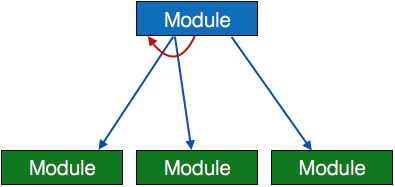
● Module - It represents a process or subroutine or task. A control module branches to more than one sub-module. Library Modules are reusable and invokable from any module.

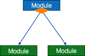
● Condition - It is represented by a small diamond at the base of the module. It depicts that the control module can select any subroutine based on some condition.
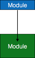
● Jump - An arrow is shown pointing inside the module to depict that the control will jump in the middle of the sub-module.
● Loop - A curved arrow represents a loop in the module. All sub-modules covered by loop repeat execution of modules.
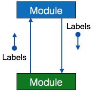
● Data flow - A directed arrow with an empty circle at the end represents data flow.

● Control flow - A directed arrow with a filled circle at the end represents control flow.
