Unit - 2
Analog signal transmission and reception
Q1) A modulating signal m(t)=10cos(2π×103t) is amplitude modulated with a carrier signal c(t)=50cos(2π×105t). Find the modulation index, the carrier power, and the power required for transmitting AM wave.
A1)
Given, the equation of modulating signal as
m(t)=10cos(2π×103t)
We know the standard equation of modulating signal as
m(t)=Amcos(2πfmt)
Comparing both equations, we get
Amplitude of modulating signal as Am=10volts
And Frequency of modulating signal as fm=103Hz=1KHz
c(t)=50cos(2π×105t)
Comparing these two equations, we will get
Amplitude of carrier signal as Ac=50volts
And Frequency of carrier signal as fc=105Hz=100KHz
μ = Am/Ac
μ = 10/50 =0.2
The value of modulation index is 0.2
Carrier power, Pc
Pc=Ac2/2R
Let R=1ohm
Carrier power, Pc is 1250 watts.
Pt=Pc(1+μ2/2)
Pt=1250(1+(0.2)22) =1275W
Q2) The equation of amplitude wave is given by s(t)=20[1+0.8cos(2π×103t)] cos(4π×105t). Find the carrier power, the total sideband power, and the band width of AM wave.
A2)
s(t)=20[1+0.8cos(2π×103t)] cos(4π×105t).
We can write above equation as
s(t)=20[1+0.8cos(2π×103t)] cos (4πx 2 x105t).

Amplitude of carrier signal as Ac=20volts
Modulation index as μ=0.8
Frequency of modulating signal as fm=103Hz=1KHz
Frequency of carrier signal as fc=2×10⁵Hz=200KHz
The formula for Carrier power, Pc
Pc=Ac2/2R
Pc = (20)2/2(1) = 200W
Total side band power is
PSB=Pcμ2/2
PSB=200× (0.8)2/2=64W
Total side band power is 64 watts.
We know the formula for bandwidth of AM wave is
BW=2fm
Substitute fm value in the above formula.
BW=2(1K) =2KHz
The bandwidth of AM wave is 2 KHz.
Q3) A carrier is phase modulated (PM) with frequency deviation of 10 kHz by a single tone frequency of 1 kHz. If the single tone frequency is increased to 2 kHz, assuming that phase deviation remains unchanged the bandwidth of the PM signal is
A3)
- In PM phase deviation,


- If the frequency
 is increased to 2 kHz and phase deviation remains unchanged.
 - The modulation index

- According to carsons rule
Bandwidth = 
Q4) Consider an FM signal  The maximum deviation of the instantaneous frequency from the carrier frequency is
A4)

A4)
- Given FM signal

- So instantaneous angle

- Instantaneous frequency
 ]
]

- We know that
- Instantaneous frequency

- Where


- Assume the given signal is of the form
- 1.
 [if carrier frequencies are same].
 - Then the given signal can be written in the form


- By applying the second condition we get [since frequencies are different in f

Q5) A device with input 𝑥(𝑡) and output 𝑦(𝑡) is characterized by: 𝑦(𝑡)=𝑥2 (𝑡). An FM signal with frequency deviation of 90 KHz and modulating signal bandwidth of 5 KHz is applied to this device. The bandwidth of the output signal is (a) 370 KHz (b) 190 KHz (c) 380 KHz (d) 95 KHz
A5)
Frequency deviation Δ𝒇=𝟗𝟎𝑲𝑯𝒛
Modulating signal bandwidth = 5 KMz
When FM signal is applied to doubler frequency deviation doubles.
𝑩. 𝑾 = 𝟐(Δ𝒇+𝒇𝒎) = 𝟐(𝟏𝟖𝟎+𝟓) =𝟑𝟕𝟎 𝑲𝑯z
Q6) An FM signal with a modulation index 9 is applied to a frequency tripler. The modulation index in the output signal will be (a) 0 (b) 3 (c) 9 (d) 27
A6)
The frequency modulation index β is multiplied by n in n-times frequency multiplier.
𝑺𝒐, 𝜷′=𝟑×𝟗 = 27
Q7) A sinusoidal modulating waveform of amplitude 5 V and a frequency of 2 KHz is applied to FM generator, which has a frequency sensitivity of 40 Hz/volt. Calculate the frequency deviation, modulation index, and bandwidth.
A7)
Given, the amplitude of modulating signal, Am=5V
Frequency of modulating signal, fm=2KHz
Frequency sensitivity, kf=40Hz/volt
We know the formula for Frequency deviation as
Δf=kfAm
Δf=40×5=200Hz
β=Δf/fm
β=200/(2×1000) = 0.1
The formula for Bandwidth of Narrow Band FM is the same as that of AM wave.
BW=2fm
BW=2×2K=4KHz
Q8) An FM wave is given by s(t)=20cos(8π×106t+9sin(2π×103t)). Calculate the frequency deviation, bandwidth, and power of FM wave.
A8)
s(t)=20cos(8π×106t+9sin(2π×103t))
We know the standard equation of an FM wave as
s(t)=Accos(2πfct+βsin(2πfmt))
Amplitude of the carrier signal, Ac=20V
Frequency of the carrier signal, fc=4×10⁶Hz=4MHz
Frequency of the message signal, fm=1×10³Hz=1KHz
Modulation index, β=9
β=Δf/fm
Δf=9×1K=9KHz
The formula for Bandwidth of Wide Band FM wave is
BW=2(β+1)fm
BW=2(9+1)1K=20KHz
The bandwidth of Wide Band FM wave is 20KHz
Pc=Ac2/2R
P= (20)2/2(1) =200W
Therefore, the power of FM wave is 200watts.
Q9) The message signal input to a modulator is m(t) = 4cos(2104 t) and the carrier is 10cos(108 t). If frequency modulation is performed with kf = 1000, verify that the modulated signal meets the criteria of being narrowband FM. Also, obtain an expression for its spectrum and sketch this spectrum.
A9)
First we calculate the modulation index 


The corresponding expression for the spectrum becomes

Where  and
and 

Q10) For commercial FM radio, the audio message signal has a spectral range of 30 Hz to 15 kHz, and the FCC allows a frequency deviation of 75 kHz. Estimate the transmission bandwidth for commercial FM using Carson’s Rule.
A10)
We know
β=Δf/fm = 75/15 =5
Using Carson's rule gives
BFM = 2(β+1)fm = 2(5+1)x15,000= 180kHz
The allowed bandwidth for commercial FM is 200 kHz.
Q11) Explain concept of modulation and demodulation?
A11)
- It is a process through which audio, video, image or text information is added to an electrical or optical carrier signal that is to be transmitted over a telecommunication or electronic medium.
- It enables the transfer of information on an electrical signal to a receiver that is capable of demodulating the signal to extract the blended information.
- It is primarily used in telecommunication technologies that require the transmission of data via electrical signals.
- It is considered the backbone of data communication as it enables the use of electrical and optical signals as information carriers.
- This is done by altering the periodic waveform or the carrier.
- This comprises of its amplitude, frequency and phase.
- Modulation has three different types:
- Amplitude Modulation (AM): Amplitude of the carrier is modulated.
- Frequency Modulation (FM): Frequency of the carrier is modulated.
- Phase Modulation (PM): Phase of the carrier is modulated.
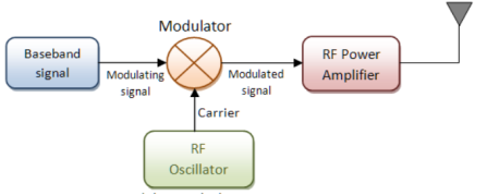
Fig.1: Modulation
Demodulation (downward frequency translation)
- It is the process of extracting the original information-carrying signal from a modulated carrier wave.
- A demodulator is an electronic circuit that is mainly used to recover the information from the modulated carrier wave.
- There are different types of demodulators.
- The output signal via demodulator may be sound, images or binary data.

Fig.2: Demodulation
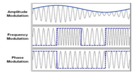
Fig.3: Demodulated Output
Q12) Explain the need of modulation?
A12)
Necessity of Modulation: -
1>. Antenna height reduces
2>. Avoids mixing of signal
3>. Increases the range of communication [ In Kilometres]
4>. Multiplexing of signals is possible
5>. Improves quality of reception of signal.
1>. Antenna height Reduces: - Antenna theory specifies that the height of the antenna required for radiation of radio waves is a function of wavelength of the frequency fed at the i/p of the antenna. Antenna height must be multiple of ( d/4 ),
Where ‘ d ‘ is the wavelength.
d = speed of light / frequency of signal
d = c / f = 3 x 10⁸ / f
Eg : Consider the voice as analog baseband signal with f = 4 KHz
d = 3 x 10⁸ / 4 x 10³
d = 75 x 103 m
d = 75 km
Height of antenna required is d / 4
= 75 km / 4 = 18.75 km
2>. Increase range of communication: - The frequency of baseband signal is low. At low frequency the signal radiation from antenna is poor or weak. Due to this reason the signal gets attenuated and can’t travel long distance when it is transmitted.
Attenuation of the transmitted signal reduces when the frequency is increased. Thus, modulation increases the frequency of the signal to be radiated. Thus, increase in frequency increases the range of communication.
Q13) Practically you cannot build the antenna of 18.7 km height. Consider this voice signal of 4 kHz frequency is used to modulate the carrier signal of 2 MHz frequency.
A13)
F = 2 MHz
D = c / f = 3 x 10⁸ / 2 x 106 = 150 m
Minimum height of antenna required = d / 4 = 150 / 4 = 37.5 m
Therefore, antenna height required for radio communication reduces from 75 km to 37.5 meters due to modulation.
Q14) What is amplitude modulation. Draw the message signal and modulated output signal too.
A14)
The amplitude of the carrier signal varies in accordance with the instantaneous amplitude of the modulating signal. That is the amplitude of the carrier signal containing no information varies as per the amplitude of the signal containing information, at each instant.
Consider the following diagram
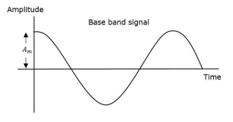
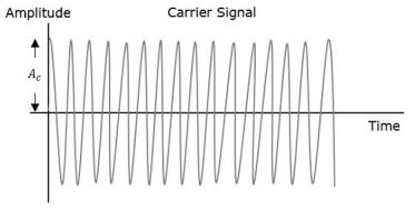
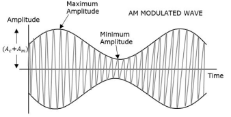
Fig.4: Amplitude Modulation
The first figure shows the modulating wave, which is the message signal. The next one is the carrier wave, which is a high frequency signal and contains no information. While, the last one is the resultant modulated wave.
It can be observed that the positive and negative peaks of the carrier wave are interconnected with an imaginary line. This line helps recreating the exact shape of the modulating signal. This imaginary line on the carrier wave is called as Envelope. It is the same as that of the message signal.
Therefore, we can say that Amplitude Modulation is the process of changing the amplitude of a relatively high frequency carrier signal in accordance with the amplitude of the modulating signal (Information). The carrier amplitude varies linearly by the modulating signal which usually consists of a range of audio frequencies. The frequency of the carrier is not affected.
The various forms of Amplitude Modulation are:
- Conventional Amplitude Modulation Full AM or Double Sideband Large carrier modulation (DSBLC) /Double Sideband Full Carrier (DSBFC)
- Double Sideband Suppressed carrier (DSBSC) modulation.
- Single Sideband (SSB) modulation
Q15) Explain generation of DSBFC (Double Side Band Full Wave Carrier)?
A15)
DSBFC (Double Side Band Full Wave Carrier)
Time-Domain Representation
Let the modulating signal be,
m(t)=Am cos(2πfmt ) --------------(1)
And the carrier signal be,
c(t)=Ac cos(2πfct)c(t) ---------------(2)
Where, Am and Ac are the amplitude of the modulating signal and the carrier signal respectively.
Fm and fc are the frequency of the modulating signal and the carrier signal respectively.
Then, the equation of Amplitude Modulated wave will be
s(t)=[Ac+ Am cos(2πfmt)] cos(2πfct) -------------------------- (3)
s(t) = [ Ac cos(2πfct) + Ac Am cos(2πfmt) . Cos(2πfct) ] ---------(4)
s(t) = Ac[1 + Am/Ac cos(2πfmt)] cos(2πfct) ----------- (5)
Here the modulation index µ = Am/Ac.
s(t) = Ac[1 + µ cos(2πfmt)] cos(2πfct) -------------- (6)
Modulation index
Let Amax and Amin be the maximum and minimum amplitudes of the modulated wave.
We will get the maximum amplitude of the modulated wave, when cos(2πfmt)
Is 1.
That is Amax=Ac + Am
We will get the minimum amplitude of the modulated wave, when cos(2πfmt)
Is -1.
That is Amin = Ac - Am
Amax + Amin = Ac + Am + Ac –Am = 2Ac
Ac = Amax + Amin/2
Similarly Amax – Amin = Ac + Am – Ac +Am = 2Am
Am = Amax – Amin /2
Therefore
µ = Amax + Amin
Amax - Amin
Bandwidth:
Bandwidth is the difference between the highest and lowest frequencies of the signal.
BW = fmax – fmin
s(t) = Ac[1+ μcos(2πfmt)] cos(2πfct)
s(t) = Ac cos(2πfct) + Ac μcos(2πfmt) cos(2πfct)
s(t) = Ac cos(2πfct) + Ac μ/2 cos 2π (fc + fm)t + Ac μ/2 cos 2π (fc - fm)t
Hence, the amplitude modulated wave has three frequencies.
- Carrier frequency fc
- Upper sideband frequency fc+fm
- And lower sideband frequency fc−fm
Here, fmax=fc+fm and fmin=fc−fm
BW=fc+fm−(fc−fm)
BW=fc+fm−(fc−fm)
BW=2fm
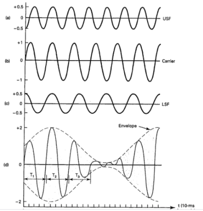
Fig.6: DSBFC
Q16) Derive the expression of power for AM?
A16)
Consider the following equation of amplitude modulated wave.
s(t)=Ac cos(2πfct)+Acμ 2 cos[2π(fc+fm)t]+ Acμ 2cos[2π(fc−fm)t] -------(1)
Power of AM wave is equal to the sum of powers of carrier, upper sideband, and lower sideband frequency components.
Pt=Pc+ PUSB+ PLSB
We know that the standard formula for power is
P = vrms 2 / R = (vm /  ) 2 /2
Where,
Vrms is the rms value of cos signal.
Vm is the peak value of cos signal.
The powers of the carrier, the upper and lower sideband is given by
Carrier power
Pc=(Ac/√2)2/R=Ac2/2R
Upper sideband power
PUSB=(Acμ/2√2)2/R= Ac2 μ2/ 8R
Similarly, for lower sideband power same as that of the upper side band power.
PLSB=(Acμ/2√2)2 /R
PLSB=Ac2μ2/R
Now, let us add these three powers in order to get the power of AM wave.
Pt=Ac2 /2R+Ac2μ2 /8R+Ac2μ2/8R
Pt= Ac2 /2R[ 1+μ2 /4+μ2 /4]
Pt=Pc ( 1+ μ 2/2 )
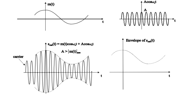
Fig.7: DSBFC
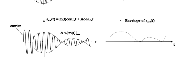
Fig.8: DSBFC
Q17) Explain DSB-SC with diagram?
A17)
In DSBC modulation, the modulated wave consists of only the upper and lower side bands. Transmitted power is saved through the suppression of the carrier wave, but the channel bandwidth requirement is the same.
DSBSC modulators make use of the multiplying action in which the modulating signal multiplies the carrier wave. In this system, the carrier component is eliminated and both upper and lower side bands are transmitted. As the carrier component is suppressed, the power required for transmission is less than that of AM.
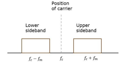
Fig.9: Position of carrier
Carrier is suppressed and base band is allowed for transmission.
If m(t) = Am cos(2πfmt) is the modulating signal and c(t) = Ac cos(2πfct) is the carrier signal then DSBSC wave s(t) is given by
s(t) = c(t) m(t) ------------------- (1)
s(t) =Am cos(2πfmt) Ac cos(2πfct) -------- (2)
s(t) = Am Ac cos(2πfmt) cos(2πfct) ------- (3)
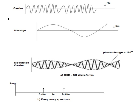
Fig.10: DSBSC
The figure shows the waveform and the frequency spectrum.
The envelope of a DSBSC modulated signal is therefore different from the message signal and the Fourier transform of s(t) is given by
S(f) = Ac/2[ M(f-fc) + M(f + fc)]
When base band signal m(t) is limited to interval –W<fc<W we find the spectrum S(f) of the DSBSC wave s(t) as shown in the figure. We see that there is a change in the scaling factor , the modulation process translates the spectrum of the base band signal by fc. The transmission bandwidth is same as AM.
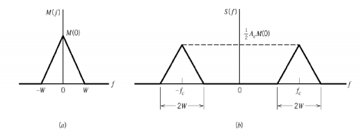
Fig.11: DSBSC transmission bandwidth
Q18) Derive expression of BW and power of DSB-SC?
A18)
Bandwidth of DSBSC Wave
We know the formula for bandwidth (BW) is
BW=fmax−fmin
Consider the equation of DSBSC modulated wave.
s(t)=AmAccos(2πfmt)cos(2πfct)s(t)
s(t)=AmAc2cos[2π(fc+fm)t]+AmAc2cos[2π(fc−fm)t]
The DSBSC modulated wave has only two frequencies. So, the maximum and minimum frequencies are fc+ fm and fc− fm respectively.
i.e.,fmax=fc+fm and fmin=fc−fm
BW=fc+fm−(fc−fm)
BW = 2fm
Thus, the bandwidth of DSBSC wave is same as that of AM wave and it is equal to twice the frequency of the modulating signal.
Power of DSBSC Wave
Consider the following equation of DSBSC modulated wave.
s(t)=AmAc2cos[2π(fc+fm)t]+AmAc2cos[2π(fc−fm)t]
Power of DSBSC wave is equal to the sum of powers of upper sideband and lower sideband frequency components.
Pt=PUSB+PLSB
We know the standard formula for power of cos signal is
P=vrms2 /R=(vm√2)2 /R
First, let us find the powers of upper sideband and lower sideband one by one.
Upper sideband power
PUSB=(AmAc/2√2)2/R=Am2Ac2 / 8R
Similarly, we will get the lower sideband power same as that of upper sideband power.
PLSB=Am2Ac2/8R
Now, let us add these two sideband powers in order to get the power of DSBSC wave.
Pt=Am2Ac2 /8R+Am2Ac2/8R
Pt=Am2Ac2 /4R
Therefore, the power required for transmitting DSBSC wave is equal to the power of both the sidebands.
Q19) Write short notes on balanced modulator and ring modulator?
A19)
Balanced Modulator (Product Modulator)
A balanced modulator consists of two standard amplitude modulators arranged in a balanced configuration so as to suppress the carrier wave as shown in the following block diagram. It is assumed that the AM modulators are identical, except for the sign reversal of the modulating wave applied to the input of one of them. Thus, the output of the two modulators may be expressed as,
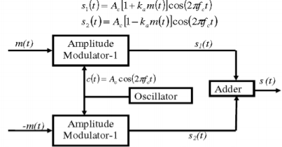
Fig.12: Balanced Modulator
Subtracting s2(t) from s1(t) we get
s(t) = s1(t) – s2(t)
s(t) = 2 ka m(t) cos(2πfct)
Hence, except for the scaling factor 2ka, the balanced modulator output is equal to the product of the modulating wave and the carrier.
Ring Modulator
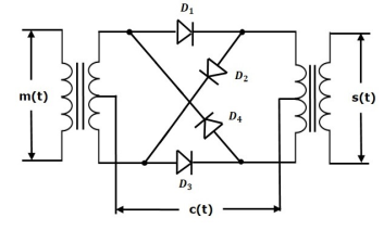
Fig.13: Ring Modulator
Operation
- In this diagram, the four diodes D1,D2,D3 and D4 are connected in the ring structure. Hence, this modulator is called as the ring modulator.
- Two center tapped transformers are used in this diagram. The message signal m(t) is applied to the input transformer, whereas, the carrier signals c(t) is applied between the two center tapped transformers.
- During the positive half cycle of the carrier signal, the diodes D1 and D3 are switched ON and the other two diodes D2 and D4 are switched OFF.
- In this case, the message signal is multiplied by +1.
- During the negative half cycle of the carrier signal, the diodes D2 and D4 are switched ON and the other two diodes D1 and D3 are switched OFF.
- In this case, the message signal is multiplied by -1. This results in 1800 phase shift in the resulting DSBSC wave.
From the above analysis, we can say that the four diodes D1, D2, D3 and D4 are controlled by the carrier signal.
If the carrier is a square wave, then the Fourier series representation of c(t) is given by
c(t) = 4 / π  n-1 / 2n -1 cos[2πfct(2n−1)]
We will get DSBSC wave s(t) which is just the product of the carrier signal c(t)) and the message signal m(t) i.e.,
s(t) = 4 / π  n-1 / 2n -1 cos[2πfct(2n−1)] m(t)
The ring modulator.
DSBSC modulators are known as product modulators as they produce the output, which is the product of two input signals.
Q20) Derive expression of power and BW for SSB-SC. Also, list its advantages?
A20)
Bandwidth of SSB-SC Wave
We know that the DSB-SC modulated wave contains two sidebands and its bandwidth is 2fm. Since the SSB-SC modulated wave contains only one sideband, its bandwidth is half of the bandwidth of DSBSC modulated wave.
i.e., Bandwidth of SSBSC modulated wave =2fm/2=fm
Therefore, the bandwidth of SSB-SC modulated wave is fm and it is equal to the frequency of the modulating signal.
Power Calculations of SSB-SC Wave
Consider the following equation of SSBSC modulated wave.
s(t)=AmAc/2 cos[2π(fc+fm)t] for the upper sideband
Or
s(t)=AmAc/2 cos[2π(fc−fm)t] for the lower sideband
Power of SSB-SC wave is equal to the power of any one sideband frequency components.
Pt=PUSB=PLSB
We know power
P=vrms2 / R
=(vm/√2)2 / R
In this case, the power of the upper sideband is
PUSB=(AmAc/2√2)2 / R = Am2Ac2 /8R.
Similarly, for lower sideband power.
PLSB=Am2Ac2 / 8R
Therefore, the power of SSB-SC wave is
Pt=Am2Ac2 / 8R
Advantages
- Bandwidth or spectrum space occupied is lesser than AM and DSBSC waves.
- Transmission of more number of signals is allowed.
- Power is saved.
- High power signal can be transmitted.
- Less amount of noise is present.
- Signal fading is less likely to occur.