Unit - 4
Delta Modulation (DM)
Q1) Figure shows a PCM wave in which the amplitude levels of +1 volt and -1 volts are used to represent binary symbols 1 and 0 respectively. The codeword used consists of three bits. Find the sampled version of an analog signal from which this PCM is derived.
A1)
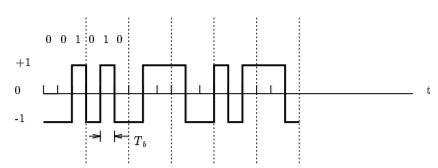
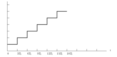
A1) The sample analog signal has the following waveform
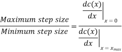
Q2) Show that the use of A-law companding provides a ratio of maximum step size to minimum step size equal to the parameter A.
A2)
For the A-law companding we have,

For small input x, the A-law is characterized by its derivatives

For large input, on the other hand, it is characterized by

Accordingly
Q3) Consider a DPCM system whose transmitter uses a first order predictor optimized in the minimum mean squared sense. Calculate the prediction gain of the system for the following values of the correlation coefficient for the
A3)
(i) 

The correlation coefficient  equals the autocorrelation function of the message signal for the delay T, normalized with respect to the mean square value of the signal.
(b) Suppose that the predictor is made suboptimal by setting the coefficient  Calculate the resulting values of the prediction gain for the two values of
  specified in part(a). What is the minimum value of
  for which the suboptimum system produces a prediction gain greater than one?
A3) (a) The prediction Gain is

As shown in the class, the prediction error variance 
(i) 

(ii) 

(ii) The prediction error is

Correspondingly, the prediction error variance is

Substituting (1) in (2), and simplifying we get

The prediction error variance is
The prediction gain is therefore

(i) 

(ii) 

The minimum value for which the prediction gain in (3) exceeds unity is when the correlation coefficient  is less than 0.5
Q4) The ramp signal x(t)=a(t) is applied to a delta modulator that operates with a sampling period  and step size =2δ
A4)
(a) Show slope-overload distortion occurs is δ<
(b) Sketch the modulator output of the following three values of the step size
(i)  (ii)
(ii)  (iii)
(iii) 
A4)
(a) In a period  the input signal rises by
  i.e.,
i.e.,  , whereas the output of the delta modulator rises by an amount equal to δ. Hence, slope overload distortion occurs if
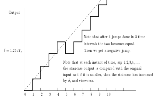
(b) For each of the three values of δ, the modulator output is as shown in Fig.
This figure illustrates that slope overload distortion occurs if
Figure is shown in next question.
Q5) Consider an adaptive delta modulator, for which the input signal  is given by
A5)

The adaption algorithm for the modulator is defined with the constant K equal to 2. The maximum and minimum permissible values of the step size are as follows:


The initial conditions are given by


Plot the stair case approximation  and the binary output for
A5) Let the sampling period  . Then

The binary output, b(n), is equal to zero if e(n)<0 and is equal to one, otherwise.

This means that I(n) is one if the binary output is one and is -1 if the binary output is zero.


For the reconstruction, we have,

Resulting in,

Initial conditions:


Using these initial conditions and inputs defining relations for the adaptive delta modulation, we get the approximation u(n), the adaptive variation of δ(n), and the resulting binary output b(n) as shown in fig.

Q6) A Delta modulated system is designed to operate at five times the Nyquist Rate. The signal bandwidth B at its input port is 3 kHz and the quantized step is 250 millivolts (0.25 volt). For this problem we assume a 2 kHz sinusoidal input – Find the maximum amplitude Am of this 2 kHz tone.
A6)
We know that B = 3 kHz, fm = 2 kHz and = 250 mV.
The Nyquist rate is 3,000 2 = 6,000 Hz. So, five time the Nyquist rate is 30,000 Hz = fs.
Using the relationship

Q7) A one kilohertz (1 kHz) signal m(t) is sampled at 8 kHz with 12-bit encoding for PCM transmission.
A7)
(a) How many bits are transmitted per second in in PCM? What is the bandwidth required in this case?
(b) Now switch to using DM with 8 kHz sampling. How many bits are transmitted per second using DM? What is the bandwidth required in using DM?
A7) We know that the signal frequency is fm = 1 kHz and the sampling rate is 8 kHz.
(a) For PCM we have 8,000 samples per second and 12 bits per sample; which equals 96,000 bits/second. The bandwidth is one-half of this giving 48,000 Hz.
(b) Now for DM we have 1 bit per sample at 8,000 samples per second. Thus, we have 8,000 bits per second and a bandwidth of 4,000 Hz.
Q8) What are M-ary systems explain in detail?
A8)
The word binary represents two bits. M represents a digit that corresponds to the number of conditions, levels, or combinations possible for a given number of binary variables.
This is the type of digital modulation technique used for data transmission in which instead of one bit, two or more bits are transmitted at a time. As a single signal is used for multiple bit transmission, the channel bandwidth is reduced.
M-ary Equation
If a digital signal is given under four conditions, such as voltage levels, frequencies, phases, and amplitude, then M = 4.
The number of bits necessary to produce a given number of conditions is expressed mathematically as
N=log2M
Where
N is the number of bits necessary
M is the number of conditions, levels, or combinations possible with N bits.
The above equation can be re-arranged as
2N=M
For example, with two bits, 22 = 4 conditions are possible.
M-ary PSK
This is called as M-ary Phase Shift Keying M−ary PSK
The phase of the carrier signal, takes on M different levels.
Representation of M-ary PSK
Si(t)=√2E/T cos(wot+ϕit) 0≤t≤T and i=1,2...M
ϕi(t)=2πiM where i=1,2,3......M
Some prominent features of M-ary PSK are −
- The envelope is constant with more phase possibilities.
- This method was used during the early days of space communication.
- Better performance than ASK and FSK.
- Minimal phase estimation error at the receiver.
- The bandwidth efficiency of M-ary PSK decreases and the power efficiency increases with the increase in M.
So far, we have discussed different modulation techniques. The output of all these techniques is a binary sequence, represented as 1s and 0s
M-ary FSK
This is called as M-ary Frequency Shift Keying M−aryFSK.
The frequency of the carrier signal, takes on M different levels.
Representation of M-ary FSK


Q9) Compare PCM, DM and ADM?
A9)
S.No | Parameter of comparison | Pulse Code Modulation (PCM) | Delta Modulation (DM) | Adaptive Delta Modulation (ADM) | Differential code pulse modulation (DPCM) |
1. | Number of bits | It can use 4,8, or 16 bits per sample | It uses only one bit for one sample | It uses only one bit for one sample | Bits can be more than one but are less than PCM |
2. | Levels and step size | The number of levels depends on number of bits Level size is fixed. | Step size is kept fixed and cannot be varied. | According to the signal variation, step size varies. | Number of levels is fixed. |
3. | Quantization error and distortion | Quantization error depends on number of levels used. | Slope overload distortion and granular noise are present. | Quantization noise is present but other errors are absent. | Slope overload distortion and quantization noise is present. |
4. | Transmission bandwidth | Highest bandwidth is required since numbers of bits are high. | Lowest bandwidth is required. | Lowest bandwidth is required. | Bandwidth required is less than PCM. |
5. | Feedback | There is no feedback in transmitter or received | Feedback exists in transmitter. | Feedback exists. | Feedback exists. |
6. | Complexity of implementation | System is complex | Simple | Simple | Simple |
Q10) Write short note on Differential PCM?
A10)
Differential pulse code modulation (DPCM) is a procedure of converting an analog into a digital signal in which an analog signal is sampled and then the difference between the actual sample value and its predicted value (predicted value is based on previous sample or samples) is quantized and then encoded forming a digital value.
DPCM code words represent differences between samples unlike PCM where code words represented a sample value.
Basic concept of DPCM - coding a difference, is based on the fact that most source signals show significant correlation between successive samples so encoding uses redundancy in sample values which implies lower bit rate.
Realization of basic concept (described above) is based on a technique in which we have to predict current sample value based upon previous samples (or sample) and we have to encode the difference between actual value of sample and predicted value (the difference between samples can be interpreted as prediction error).
Because it's necessary to predict sample value DPCM is form of predictive coding.
DPCM compression depends on the prediction technique, well-conducted prediction techniques lead to good compression rates, in other cases DPCM could mean expansion comparing to regular PCM encoding.

Fig.: DPCM
Q11) Explain DM and also list its advantages?
A11)
Delta Modulator
The Delta Modulator comprises of a 1-bit quantizer and a delay circuit along with two summer circuits. Following is the block diagram of a delta modulator.
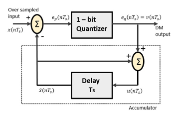
Fig.: Delta Modulator
The predictor circuit in DPCM is replaced by a simple delay circuit in DM.
From the above diagram, we have the notations as −
- x(nTs)= over sampled input
- Ep(nTs) = summer output and quantizer input
- Eq(nTs) = quantizer output = v(nTs)
- xˆ(nTs) = output of delay circuit
- u(nTs) = input of delay circuit
Using these notations, now we shall try to figure out the process of delta modulation.
Ep(nTs)=x(nTs)−xˆ(nTs) ---------equation 1
=x(nTs)−u([n−1]Ts
=x(nTs)−[xˆ[[n−1]Ts]+v[[n−1]Ts]] -------equation 2
Further,
v(nTs)=eq(nTs)=S.sig.[ep(nTs)] ---------equation 3
u(nTs)=xˆ(nTs)+eq(nTs)
Where,
- xˆ(nTs) = the previous value of the delay circuit
- Eq(nTs) = quantizer output = v(nTs)
Hence,
u(nTs)=u([n−1]Ts)+v(nTs) ---------equation 4
Which means,
The present input of the delay unit
= The previous output of the delay unit + the present quantizer output the present quantizer output
Assuming zero condition of Accumulation,

Accumulated version of DM output =  --------equation 5
Now, note that
xˆ(nTs)=u([n−1]Ts)
= ---------equation 6
Delay unit output is an Accumulator output lagging by one sample.
From equations 5 & 6, we get a possible structure for the demodulator.
A Stair-case approximated waveform will be the output of the delta modulator with the step-size as delta (Δ). The output quality of the waveform is moderate.
Delta Demodulator
The delta demodulator comprises of a low pass filter, a summer, and a delay circuit. The predictor circuit is eliminated here and hence no assumed input is given to the demodulator.
Following is the diagram for delta demodulator.
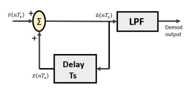
Fig.2 Delta Demodulator
From the above diagram, we have the notations as −
- vˆ(nTs) is the input sample
- uˆ(nTs) is the summer output
- x¯(nTs) is the delayed output
A binary sequence will be given as an input to the demodulator. The stair-case approximated output is given to the LPF.
Low pass filter is used for many reasons, but the prominent reason is noise elimination for out-of-band signals. The step-size error that may occur at the transmitter is called granular noise, which is eliminated here. If there is no noise present, then the modulator output equals the demodulator input.
Advantages of DM Over DPCM
- 1-bit quantizer
- Very easy design of the modulator and the demodulator
Q12) What are the limitation of DM explain in detail?
A12)
Delta modulation is subject to rate of rise over load problems whenever the input changes too rapidly for the stepped wave form to follow it. If the input signal level remains constant, the reconstructed Delta modulation waveform exhibits a hunting behaviour known as idling noise. This idling noise is a square wave at one half the clock rate. If the clock rate is much greater than twice the highest frequency in the input signal, most of the idling noise can be filtered out at the receiver.

Fig 3 Slope Overload
Slope Overload: Slope overload distortion occurs when the analog input signal changes at a faster rate than the DAC can maintain it, the slope of the analog signal is greater than the delta modulator can maintain. In general, when the slope of stair case is less than (or) equal to modulating signal, the slope overloading occurs. Increasing the clock frequency reduces the probability of slope overload occurring. General method to reduce the slope overload is to increase the magnitude of the size. Assume the input for Delta modulation be f(t) = A cos ωmt.

If the step size used in the Delta modulation system is ‘Δ’, then the maximum (rate of rise) slope over load is / Ts


Granular noise: In general, Granular noise occurs
- When the original analog input signal has a relatively constant amplitude, the reconstructed signal has variations that were not present in the original signal. This is called granular noise
- The granular noise is analogous to the quantization noise in a PCM system.
- When the step size Δ is too large relative to the local slope characteristics of the input waveform x(t), thereby causing the stair case approximation u(t) to hunt around a relatively flat segment of the input waveform Granular noise can be reduced by decreasing the step size so that the stair case approximation may become more closer to the modulating signal.
There is a need to have a large step size to accommodate a wide dynamic range, whereas small step size is required for the accurate representation of relatively low-level signals.


Therefore, a granular noise can be removed by taking a small resolution of step size and a slope over load distortion can be removed by taking a large resolution.
Q13) With the help of block diagram explain ADM?
A13)
In digital modulation, we have come across certain problem of determining the step-size, which influences the quality of the output wave.
A larger step-size is needed in the steep slope of modulating signal and a smaller step size is needed where the message has a small slope. The minute details get missed in the process. So, it would be better if we can control the adjustment of step-size, according to our requirement in order to obtain the sampling in a desired fashion. This is the concept of Adaptive Delta Modulation.
Following is the block diagram of Adaptive delta modulator.
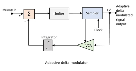
Fig. 4 Adaptive delta modulator
The gain of the voltage-controlled amplifier is adjusted by the output signal from the sampler. The amplifier gain determines the step-size and both are proportional.
ADM quantizes the difference between the value of the current sample and the predicted value of the next sample. It uses a variable step height to predict the next values, for the faithful reproduction of the fast-varying values.
Q14) Derive expression of SNR in DM?
A14)
Signal to Noise Ratio of Delta modulation system: It is the ratio of Signal power to the noise power Signal power=p
Quantization noise power=E[e2]
 (limits from - to )
 (limits from - to )


Signal power p= V2/2
Amplitude = Am
V=Am/√2
Signal Power = p = Am2/2R
Normalised Signal Power R=1, then P= Am2/2
To avoid the slope overload error in the delta modulation, the amplitude Am≤ 
By substituting, the normalised power signal power

Then the signal to noise ratio

Q15) What are feature of DM and what exactly is DM explain?
A15)
The type of modulation, where the sampling rate is much higher and in which the step size after quantization is of a smaller value Δ, such a modulation is termed as delta modulation.
Features
- The quality is moderate.
- The design of the modulator and the demodulator is simple.
- The stair-case approximation of output waveform.
- The step-size is very small, i.e., Δ delta.
- The bit rate can be decided by the user.
- This involves simpler implementation.
Delta Modulation is a simplified form of DPCM technique, also viewed as 1-bit DPCM scheme. As the sampling interval is reduced, the signal correlation will be higher.