Unit - 3
Solution of the One-Dimensional Wave Equation
Q1) Derive one-dimensional wave equation?
A1) The one-dimensional wave equation is given by

|
In order to specify a wave, the equation is subject to boundary conditions
 (2)
(2)
 (3)
(3)
and initial conditions
 (4)
(4)
 (5)
(5)
The one-dimensional wave equation can be solved exactly by d'Alembert's solution, using a Fourier transform method, or via separation of variables.
d'Alembert devised his solution in 1746, and Euler subsequently expanded the method in 1748. Let
 (6)
(6)
 (7)
(7)
By the chain rule,


The wave equation then becomes
| (10) |
Any solution of this equation is of the form

where  and
and  are any functions. They represent two waveforms traveling in opposite directions,
  in the negative
  direction and
  in the positive
  direction.
The one-dimensional wave equation can also be solved by applying a Fourier transform to each side,

which is given, with the help of the Fourier transform derivative identity, by

Where
 (14)
(14)
 (15)
(15)
This has solution

Taking the inverse Fourier Transform gives
 (17)
(17)
 (18)
(18)
 (19)
(19)
 (20)
(20)
Where
 (21)
(21)
 (22)
(22)
This solution is still subject to all other initial and boundary conditions.
The one-dimensional wave equation can be solved by separation of variables using a trial solution
 (23)
(23)
This gives
 (24)
(24)

So, the solution for  is
is
 (26)
(26)
Rewriting (25) gives
 (27)
(27)
so, the solution for T is
 (28)
(28)
Where  . Applying the boundary conditions
  to (◇) gives
 (29)
(29)
where m is an integer.
 (30)
(30)

The initial condition  then gives
  so (31) becomes
 (32)
(32)
The general solution is a sum over all possible values of m, so
 (33)
(33)
Using orthogonality of sines again,

where  is the Kronecker delta defined by

Gives


so, we have

The computation of  s for specific initial distortions is derived in the Fourier sine series section. We already have found that
  ,
,


where the  coefficients are given by (◇).
A damped one-dimensional wave

given boundary conditions
 (43) and
initial conditions
 (45)
(45)
 (46)
(46)
and the additional constraint
 (47)
(47)
can also be solved as a Fourier Series

Where:

 (49)
(49)
 (50)
(50)
Q2) Derive relation between E, H and depth of penetration?
A2) Maxwell’s equation in free space is given by
 ------------------------(1)
This gives a relation between the amplitude vector E~ 0 and the wave vector ~k as
 -------------------------(2)
Since E~ 0 gives the direction of the electric field at all points in space, and ~k gives the direction of propagation of the wave, equation (2) tells us that plane electric waves in free space are transverse waves.
We can also derive a wave equation for the magnetic field, starting from Maxwell’s equation (in free space):
 ---------------------------(3)
Taking the curl, as before, and using a vector identity gives:
 -------------------------(4)
Using ∇· B~ = 0, and substituting for ∇× E~ from Maxwell’s equation gives:
 --------------------------------(5)
which has the solution:
 ------------------------------------------(6)
To check that our solution for the magnetic wave equation satisfies Maxwell’s equations.
In this case, we find from ∇· B~ = 0 that the wave is once again a transverse wave
 -----------------------------------------(7)
The solutions for the electric and magnetic fields simultaneously satisfy Maxwell’s equations. We find


These results tell us that the electric and magnetic fields and the wave vector must be mutually perpendicular...
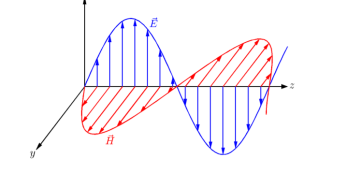
We also find the relationship between the amplitudes of the electric and magnetic fields

Where c is

The ratio between the amplitudes of E~ and H~ in a plane wave in free space defines the impedance of free space, Z0:

The penetration of a wave in a material is about its wavelength.
Q3) Derive expression for field equation when there is penetration of different mediums?
A3) From Maxwell’s equation in electric field E and magnetic field H the following equations of the propagation of the wave is:


Let us pass in the field of Fourier then


The last equation is known as Helmholtz where:
Ist case:

Here k is real. Hence, EM waves are sensitive to the dielectric permittivity  For temporal field we have

It is the term of propagation.
2nd case: 
The physical property is the electrical conductivity σ . In the temperal field

The amplitude decreases with distance characteristics.

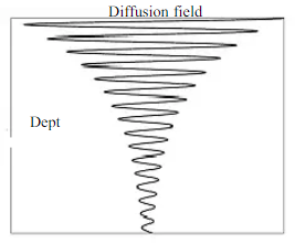
An EM wave will see its amplitude decreasing by a factor 1/e to a depth  = 1/β m.
Q4) What is polarization of plane wave?
A4) The electromagnetic wave consists of electric and magnetic fields vibrating at right angles to each other therefore it is necessary to adopt a convention to determine the polarization of the signal. For this purpose, an electric field is used.
Vertical and horizontal polarization fall into the category known as linear polarization. The wave can be thought of as vibrating in one plane which is up and down or side to side.
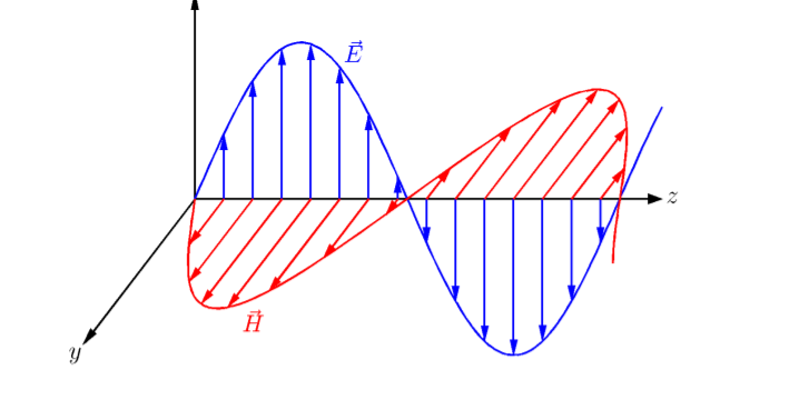
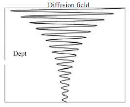

Fig: Polarization
Circular polarization can be visualized by imagining a signal propagating from an antenna that is rotating. The tip of the electric field vector can be seen to trace out a helix or corkscrew as it travels away from the antenna.
Circular polarization can be either right or left- handed dependent upon the direction of rotation as seen from the transmitting antenna.
Elliptical polarization. This occurs when there is a combination of both linear and circular polarization. This can be visualized by imagining the tip of the electric field tracing out an elliptically shaped corkscrew.
Q5) Derive expression of field when incident wave is normal?
A5) Consider the plane wave travelling in the x direction which is incident upon the surface of a perfect conduction as shown in figure 6.1. Assuming the medium in which the wave is travelling to be perfect we have P= jβ as because α = 0. Since the surface upon which the wave is incident is perfect conductor the depth of penetration δ =0. The wave is entirely perfect reflected so that none of the energy of the incident wave can be transmitted. Is the expression for the electric field of the incident wave is


Figure: Electric field and magnetic field standing waves
And the surface of the perfect conductor is taken to be x=0 plane as shown in figure 6.1. The expression for reflected wave will be

At the boundary, we must have  tangential component continuous and since E is zero within the conductor,
  just outside the conductor must be zero.
This means that at x=o


Or,
The resultant of total electric field strength at any point at a distance -x from x=0 plane will be some of the field strength of the incident and reflected waves at that point and will be given by


Expressing time variation explicitly, we have

If  is chosen to be real


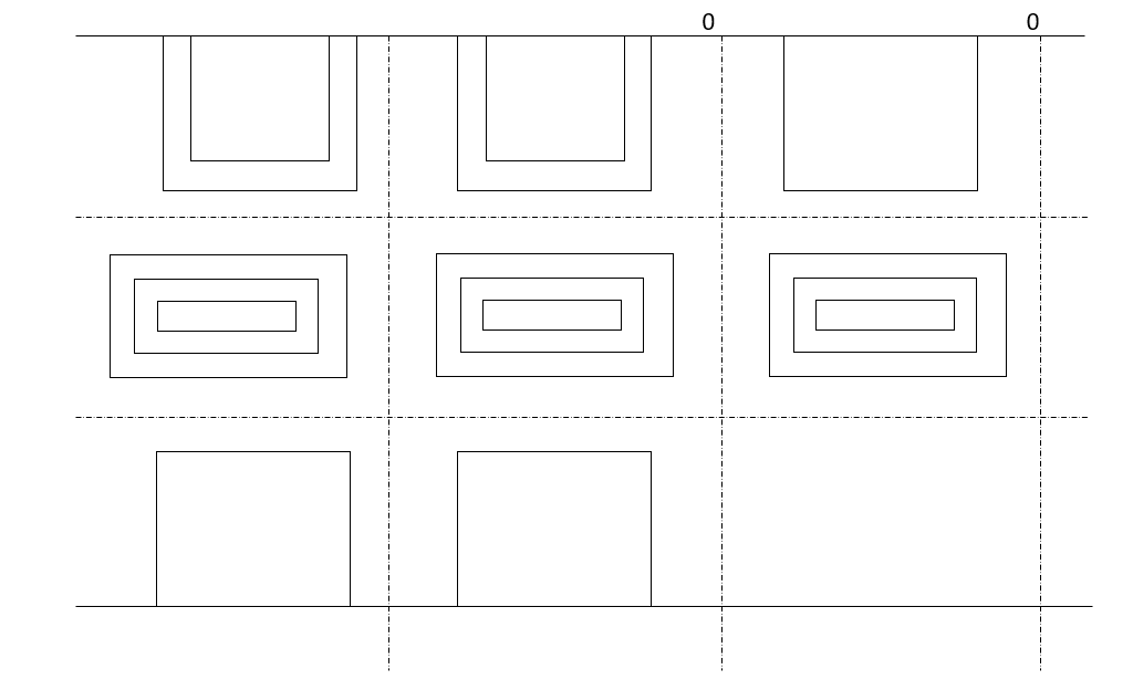
Equation 6.4 shows that the incident and reflection waves combine to produce a standing wave which does not progress. The magnitude of the electric field varies sinusoidally with distance from the reflecting plane. It is zero at the surface and at multiples of x/2 from the surface. It has maximum value of twice the electric field strength of the incident wave at distance from the surface that are odd multiple of x/4 as shown in figure 6.1.
Now in order to meet the condition of reversal of direction of energy propagation the phase of the reflected magnetic field strength  at the surface of reflection x=0 because if both magnetic and electric field strength are reversed, there is no reversal of the direction of energy propagation. Thus


Since  is in phase with
  and real


The resultant electric and magnetic field strengths are shown in figure 6.1. Equation 6.4 and 6.5 show that  are out of phase by
  radiance or 90° due to additional j factor in equation 6.4 and hence there is no average flow of power.
Q6) Derive the expression of field when wave is oblique incidence?
A6) Whenever a wave is incident obliquely on the interface between two media, two cases will arise: -
(A) “Horizontal polarization”- In this case electrical vector parallel to the boundary surface or perpendicular to the plane of incidence. While the plane of incidence ray and normal to the surface. Most significant for horizontal polarization is perpendicular polarization because electrical vector is perpendicular to the plane of incidence.
This case is shown in figure 3 (a)

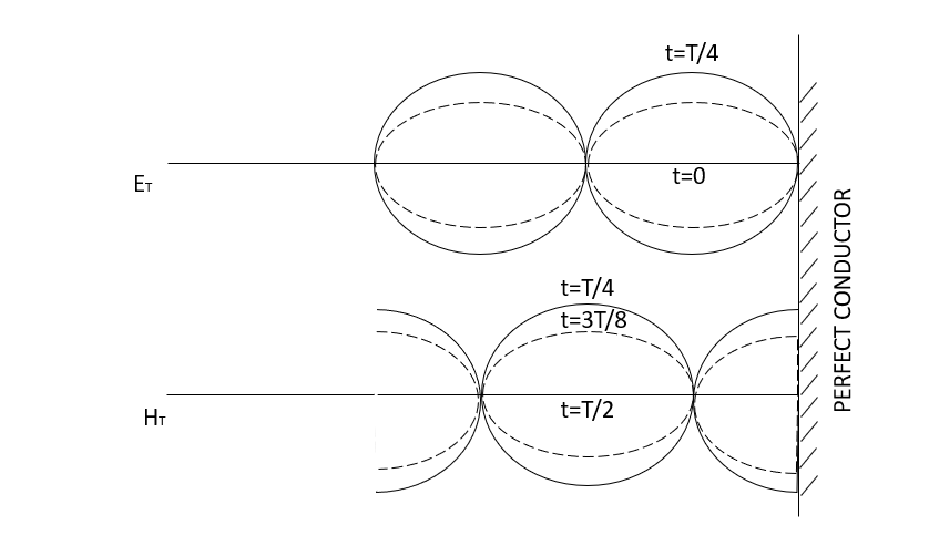
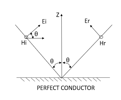
Figure: Oblique incidence having horizontal polarization
Let the incident and reflected waves makes angle  with the z- axis as shown in figure 4. the expression for the reflected wave is


Where, are the direction cosine of the vector
  is the amplitude of the electric field strength of the reflected wave at the origin.
For the wave normal of the reflected wave

= y sin  + z cos
Putting this value in  expression in the expression

Similarly for the incident wave


Therefore, 
Applying boundary condition that is

The total electric field will be given by


Phase shift constant in z and y direction only.
Equation 6.5 gives a standing wave distribution of electric field along the z axis. The wavelength  measured along the axis is greater than the wavelength of the incident wave. Hence

The planes of zero electric field occur that multiples of from reflecting surface. The two planes of maximum electric field strength occur at odd multiples of  from the surface. The planes oh maximum electric field strength occurs at odd multiple
  of from the equation.
The whole standing wave distribution of electric field strength is seen from equation 6.5 to be travelling in y direction with a velocity

This is the velocity with which arrest of the incident wave moves along y axis point the wavelength in this direction is

The spatial distribution of the magnetic field  at a given time is shown in figure 6.4. it may be seen that pattern repeats itself with change of sign every
  and a conducting plane may be placed at these
  levels without disturbing the field pattern. The concept will be used in treatment of guided waves.
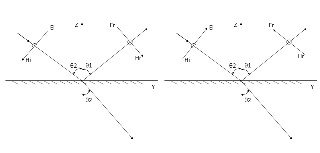
Figure: Spatial distribution of the magnetic field
(B) “Vertical polarization”-
In this case the magnetic vector is parallel to the boundary surface and electric vector is parallel to the plane of incidence. Most significant designation for the vertical polarization is parallel polarization because the electric vector is parallel to the plane of incidence. This case is shown in figure 6.2 (b)
Let the instantaneous directions of  be as shown in figure 6.5. Since the magnetic field
  will be reflected without phase reversal we have

And, 


The total magnetic field strength will be

Whereas before


Thus, the magnetic field strength has a standing wave distribution in the z direction with the plains of maximum H located at the conducting surface and at multiples of  from the surface. The plains of zero magnetic field strength occurs at odd multiples of
  from the surface.
Now for the incident wave


For the reflected wave


The total Z component of electric field strength
 6.11(a)
The total y component of electric field is
 6.11 (b)
Both components of the electric field strength have a standing wave distribution above the reflecting plane. However, for the normal or Z component of  the maxima occur at the plane and multiples of
  from the plane where as for the components of E parallel to reflecting plane, the Maxima occurs at the plane and the multiples of
  from the plane.
As indicated in the electric field distribution, in figure 6.6 the pattern repeats itself every  in the Z direction.
If we place conducting shuts in y-z plane, this will make no difference insofar the wave propagation and field distribution are concerned. This concept will find application in the study of guided waves.
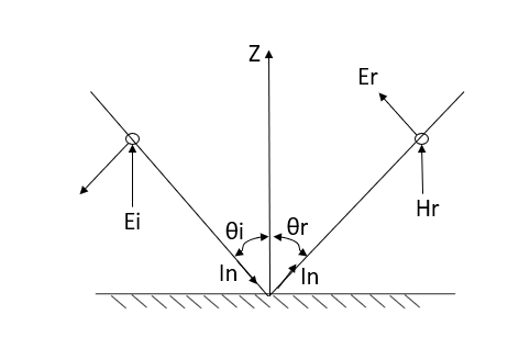
Figure: Oblique incident having vertical polarization
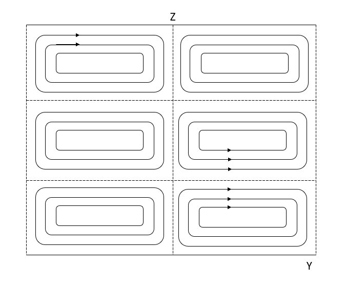
Figure: Spatial distribution of electrical field E.
Q7) Derive expression for Reflection of a Uniform Plane Wave Incident Normally on a Perfect Conductor and at the Interface of Two Dielectric Regions
A7) A uniform plane wave with x-directed electric field is normally incident upon a perfectly conducting plane at z =0, as shown in Figure. The presence of the boundary gives rise to a reflected wave that propagates in the -z direction. There are no fields within the perfect conductor. The known incident fields traveling in the +z direction can be written as


while the reflected fields propagating in the -z direction are similarly


Where in the lossless free space

The minus sign difference in the spatial exponential phase factors of (1) and (2) as the waves are traveling in opposite directions. The amplitude of incident and reflected magnetic fields are given by the ratio of electric field amplitude to the wave impedance.
The negative sign in front of the reflected magnetic field for the wave in the -z direction arises because the power flow S, = E, x H, in the reflected wave must also be in the -z direction. The total electric and magnetic fields are just the sum of the incident and reflected fields. The only unknown parameter E, can be evaluated from the boundary condition at z =0 where the tangential component of E must be continuous and thus zero along the perfect conductor:
The total fields are the sum of incident and reflected fields

=
=

=
=
The electric and magnetic fields are 90* out of phase with each other both in time and space.
Reflection by perfect dielectric- normal incidence
The perfect conductor with a lossless dielectric of permittivity  and permeability
  , as in Figure with a uniform plane wave normally incident from a medium
  with permittivity and permeability
  . In addition to the incident and reflected fields for z 0.
The unknown quantities 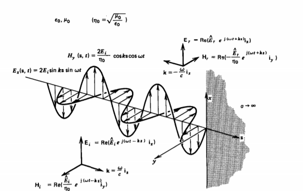 and
and 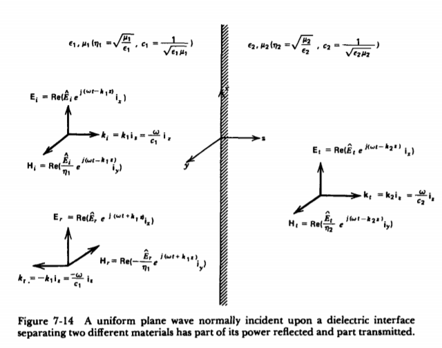 can be found from the boundary conditions of continuity tangential E and H at z=0,


From which we find reflection R and transmission field T field co-efficients as


Where 1 + R = T.
Q8) What is SWR?
A8) Standing waves represent power that is not accepted by the load and reflected along the transmission line or feeder.
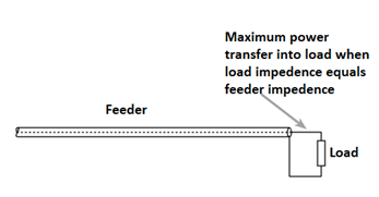
In order to obtain the maximum power transfer from the source to the transmission line, or the transmission line to the load, be it a resistor, an input to another system, or an antenna, the impedance levels must match.

Fig: Matched Feeder and load
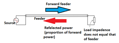
Issues arise when power is transferred into the transmission line or feeder and it travels towards the load. If there is a mismatch, i.e., the load impedance does not match that of the transmission line, then it is not possible for all the power to be transferred.
As power cannot disappear, the power that is not transferred into the load has to travel somewhere and there it travels back along the transmission line back towards the source.

Fig: Power reflected when feeder and load impedance does not match
When this happens the voltages and currents of the forward and reflected waves in the feeder add or subtract at different points along the feeder according to the phases. In this way standing waves are set up.
If one end is fixed a standing wave motion is set up, and points of minimum and maximum vibration can be seen.
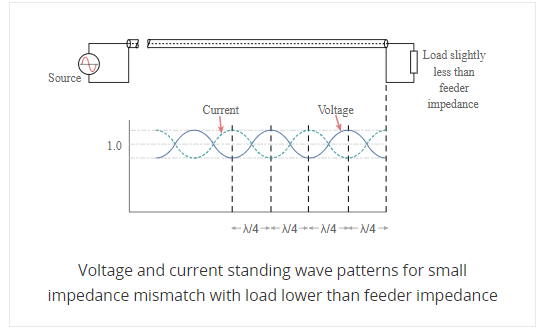
The values of current and voltage along the feeder vary along the feeder. For small values of reflected power, the waveform is almost sinusoidal, but for larger values it becomes more like a full wave rectified sine wave. This waveform consists of voltage and current from the forward power plus voltage and current from the reflected power.
At a distance a quarter of a wavelength from the load the combined voltages reach a maximum value whilst the current is at a minimum. At a distance half a wavelength from the load the voltage and current are the same as at the load.
A similar situation occurs when the load resistance is greater than the feeder impedance however this time the total voltage at the load is higher than the value of the perfectly matched line. The voltage reaches a minimum at a distance a quarter of a wavelength from the load and the current is at a maximum. However, at a distance of a half wavelength from the load the voltage and current are the same as at the load.
Then when there is an open circuit placed at the end of the line, the standing wave pattern for the feeder is similar to that of the short circuit, but with the voltage and current patterns reversed.
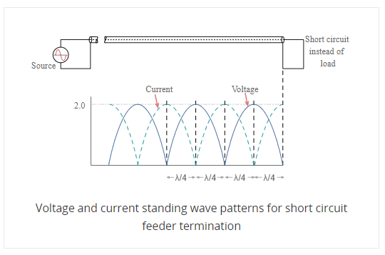
SWR stands for standing wave ratio. It describes the voltage and current standing waves that appear on the line. It is a generic description for both current and voltage standing waves. It is often used in association with meters used to detect the standing wave ratio. Both current and voltage rise and fall by the same proportion for a given mismatch.
Q9) Derive Oblique Incidence of a Plane Wave at the Boundary between Two Regions?
A9) We consider the problem of reflection and transmission from a planar boundary between semi-infinite media for a transverse electric (TE) uniform plane wave.
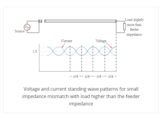
Fig: Oblique incidence between the two semi-infinite material regions
The boundary between the two semi-infinite and lossless regions is located at the z=0z=0 plane. The wave is incident from Region 1. The electric field intensity E˜TEi of this wave is given by

In this expression, ris the position at which E˜iTE is evaluated, and

There, as here, the symmetry of the problem indicates that the reflected and transmitted components of the electric field will have the same polarization as that of the incident electric field. This is because there is nothing present in the problem that could account for a change in polarization. Thus, the reflected and transmitted fields will also be TE. Therefore, we postulate the following expression for the reflected wave


indicates the direction of propagation, which is also currently unknown.
Similarly, we postulate the following expression for the transmitted wave:

where C is an unknown, possibly complex-valued constant to be determined

At this point, the unknowns in this problem are the constants BB and CC, as well as the directions k^r and k^t. We may establish a relationship between EiTEETEi, BB, and CC by application of boundary conditions at z=0z=0. First, recall that the tangential component of the total electric field intensity must be continuous across material boundaries. To apply this boundary condition, let us define E˜1E~1 and E˜2E~2 to be the total electric fields in Regions 1 and 2, respectively. The total field in Region 1 is the sum of incident and reflected fields, so


Next, note that all electric field components are already tangent to the boundary. Thus, continuity of the tangential component of the electric field across the boundary requires E˜1(0) =E˜2(0)E~1(0) =E~2(0), and therefore


Dropping the vector (y^y^) since it is the same in each term, we obtain:


Essentially, we are requiring the phases of each field in Regions 1 and 2 to be matched at every point along the boundary. Any other choice will result in a violation of boundary conditions at some point along the boundary. This phase matching criterion will determine the directions of propagation of the reflected and transmitted fields. The second equation is obtained by applying the appropriate boundary conditions to the magnetic field.
Specifically, the cross product of the electric and magnetic fields should point in the direction of propagation. Expressions for each of the magnetic field components is determined formally below.
From the plane wave relationships, we determine that the incident magnetic field intensity is


Similarly, we determine that the reflected magnetic field has the form:


The transmitted magnetic field has the form


The total magnetic field in Region 1 is the sum of incident and reflected fields, so

The magnetic field in Region 2 is

Since there is no current on the boundary, the tangential component of the total magnetic field intensity must be continuous across the boundary. Expressed in terms of the quantities already established, this boundary condition requires

where “x^” selects the component of the magnetic field that is tangent to the boundary. Evaluating this expression, we obtain

The result is shown below

Solving this equation for B

We can express this result as a reflection coefficient as


It is worth noting above equation becomes the reflection coefficient for normal (TEM) incidence when


Q10) Oblique Incidence of a Plane Wave on a Flat Perfect Conductor and at the Boundary between Two Perfect Dielectric Regions
A10) Let us consider two lossless dielectric media with  and
and  and
and  and
and  respectively separated by a planar interface as shown below. Let the incident wave with electric field E1i and of angular frequency ω, propagate in medium 1 toward the interface, normal to it, with the vector E parallel to the x-axis.
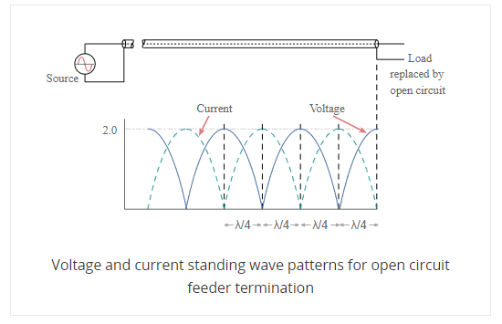
Fig: Two lossless dielectric media divided by planar interface
A part of the incident electromagnetic energy will be reflected from the interface and a part will be transmitted into medium 2. The fields will be of the form.
 ,
, 
 ,
, 


We can now write the boundary condition

By solving these two equations we get
 ,
, 
The ratio of E1r/E1i is known as reflection coefficient and E2/E1i is called the transmission coefficient.
 (The reflection coefficient, dimensionless)
 (The transmission coefficient, dimensionless)
In medium 2 there is only progressive transmitted wave. In medium 1, however we have the incident wave and reflected wave, the total field being the sum of two.

The electric field in medium 1 is therefore of the same form as the voltage in the analogous transmission line. If  then
then

The expression is minimal, equal to (1- ), in planes. The resultant wave in medium 1 can be
 (>0)
(>0)
 (>0)
(>0)
The ratio analogous to the voltage SWR from transmission lines is

