Unit - 2
Standard test signals
Q1) Sketch the root locus for given open loop transfer function G(S) =  .
.
A1) G(s) = 
Number of Zeros = 0
Number of polls S = (0, -1+j, -1-j) = (3).
1) Number of Branches = max (P, Z) = max (3, 0) = 3.
2) As there are no zeros in the system so, all branches terminate at infinity.
3) As P>Z, branches terminate at infinity through the path shown by asymptotes
Asymptote =  × 180° q = 0, 1, 2………..(p-z-1)
P=3, Z=0.
q= 0, 1, 2.
For q=0
Asymptote = 1/3 × 180° = 60°
For q=1
Asymptote =  × 180°
= 180°
For q=2
Asymptote =  × 180° = 300°
Asymptotes = 60°,180°,300°.
4) Asymptote intersects real axis at centroid
Centroid =
= 
Centroid = -0.66
5) As poles are complex so angle of departure
øD = (2q+1)×180°+ø
ø = ∠Z –∠P.
Calculating ø for S=0
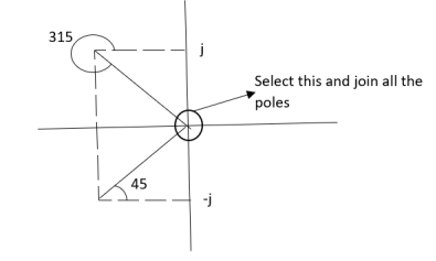
Join all the other poles with S=0
ø = ∠Z –∠P.
= 0-(315°+45°)
= -360°
ØD = (2q + 1)180 + ø.
= 180° - 360°
ØD = -180° (for q=0)
= 180° (for q=1)
=540° (for q=2)
Calculation ØD for pole at (-1+j)
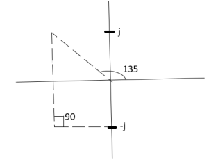
ø = ∠Z –∠P.
= 0 –(135°+90°)
= -225°
ØD = (2q+1) 180°+ø.
= 180-225°
= -45°
ØD = -45° for q = 0)
= 315° (for q = 1)
= 675° (for q =2)
6) The crossing point on imaginary axis can be calculated by Routh Hurwitz the characteristic equation is.
1+G(s) H (s) = 0
1+
S (S2+2s+2)+k = 0
S3+2s2+2s+K = 0
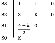
For stability  > 0. And K > 0.
0<K<2.
So, when K=2 root locus crosses imaginary axis
S3 + 2S2 + 2S + 2 =0
For k
Sn-1 = 0 n: no. Of intersection
S2-1 = 0 at imaginary axis
S1 = 0
 = 0
= 0
K<4
For Sn = 0 for valve of S at that K
S2 = 0
2S2 + K = 0
2S2 + 2 = 0
2(S2 +1) = 0
32 = -2
S = ± j 
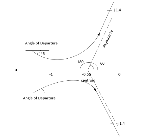
The root locus plot is shown in figure.
Q2) Sketch the root locus plot for the following open loop transfer function
G(s) = 
A2)
- Number of zero = 0, number of poles = 3
- As P>Z, branches will terminates at infinity
- There are no zeros so all branches will terminate at infinity.
- The path for the branches is shown by asymptote
Q3) Plot the root locus for the given open loop transfer function
G(s) = 
A3)
- Number of zeros = 0 number of poles = 4
P = (S=0,-1,-1+j,-1-j) = 4
2. As P>Z all the branches will terminated at infinity.
3. As no zeros so all branches terminate at infinity.
4. The path for branches is shown by asymptote.
Asymptote =  ×180°. q=0,1,………p-z-1
P=3, Z=0
q= 0,1,2.
For q = 0
Asymptote =  × 180° = 60.
For q=1
Asymptote =  × 180° = 180°
For q=2
Asymptote =  × 180° = 300°
5. Asymptote intersect real axis at centroid
Centroid = 
=  = -1
= -1
6. As root locus lies between poles S= 0, and S= -1
So, calculating breakaway point.
 = 0
= 0
The characteristic equation is
1+ G(s) H (s) = 0.
1+  = 0
= 0
K = -(S3+3S2+2s)
 = 3S2+6s+2 = 0
3s2+6s+2 = 0
S = -0.423, -1.577.
So, breakaway point is at S=-0.423
Because root locus is between S= 0 and S= -1
7. The intersection of root locus with imaginary axis is given by Routh criterion.
Characteristics equation is
S3+3S3+2s+K = 0
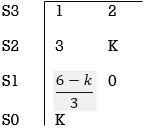
For k
Sn-1= 0 n: no. Of intersection with imaginary axis
n=2
S1 = 0
 = 0
= 0
K < 6 Valve of S at the above valve of K
Sn = 0
S2 = 0
3S2 + K =0
3S2 +6 = 0
S2 + 2 = 0
S = ±  j
j
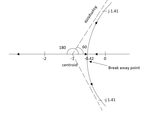
Fig. Root Locus for G(s) = 
The root locus plot is shown in figure.
Q4) Plot the root locus for open loop system G(s) = 
A4)
1) Number of zero = 0 number of poles = 4 located at S=0, -2, -1+j, -1-j.
2) As no zeros are present so all branches terminated at infinity.
3) As P>Z, the path for branches is shown by asymptote
Asymptote = 
q = 0,1,2……p-z-1
For q = 0
Asymptote = 45°
q=1
Asymptote = 135°
q=2
Asymptote = 225°
q=3
Asymptote = 315°
4) Asymptote intersects real axis at centroid.
Centroid = 
= 
Centroid = -1.
5) As poles are complex so angle of departure is
ØD=(2q+1)180° + Ø
ø = ∠Z –∠P
= 0-[135°+45°+90°]
= 180°- 270°
ØD = -90°
6) As root locus lies between two poles so calculating point. The characteristic equation is
1+ G(s)H(s) = 0
1+ = 0.
= 0.
K = -[S4+2S3+2S2+2S3+4S2+4S]
K = -[S4+4S3+6S2+4S]
 = 0
= 0
 = 4s3+12s2+12s+4=0
S = -1
So, breakaway point is at S = -1
7) Intersection of root locus with imaginary axis is given by Routh Hurwitz.
S4+4S3+6S2+4s+K = 0

 ≤ 0
≤ 0
K≤5.
For K=5 valve of S will be.
5S2+K = 0
5S2+5 = 0
S2 +1 = 0
S2 = -1
S = ±j.
The root locus is shown in figure.
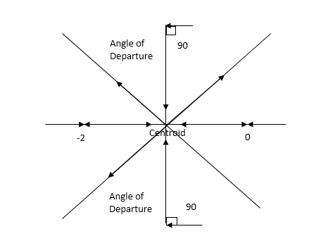
Fig. Root Locus For G(s) = 
Q5) Plot the root locus for open loop transfer function G(s) = 
A5)
- Number of zeros = 0. Number of poles = 4 located at S=0, -3, -1+j, -1-j.
- As no. Zero so all branches terminate at infinity.
- The asymptote shows the both to the branches terminating at infinity.
Asymptote =  q=0,1,….(p-z).
For q = 0
Asymptote = 45
For q = 1
Asymptote = 135
For q = 2
Asymptote = 225
For q = 3
Asymptote = 315
(4). The asymptote intersects real axis at centroid.
Centroid = ∑Real part of poles - ∑Real part of zero / P – Z
= [-3-1-1] – 0 / 4 – 0
Centroid = -1.25
(5). As poles are complex so angle of departure
φD = (29 + 1)180 + φ
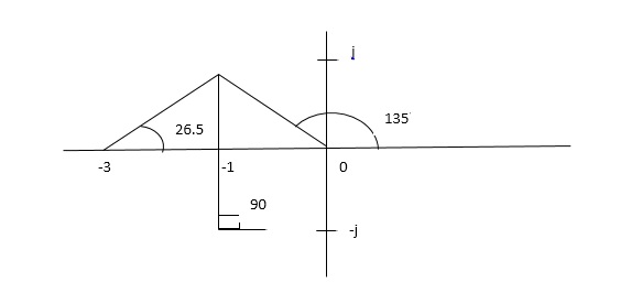
ø = ∠Z –∠P.
= 0 – [ 135 + 26.5 + 90]
= -251.56
For q = 0
φD = (29 + 1)180 + φ
= 180 – 215.5
φD = - 71.56
(6). Break away point dk / ds = 0 is at S = -2.28.
(7). The intersection of root locus on imaginary axis is given by Routh Hurwitz.
1 + G(S)H(S) = 0
K + S4 + 3S3 + 2S3 + 6S2 + 2S2 + 6S = 0
S4 1 8 K
S3 5 6
S2 34/5 K
S1 40.8 – 5K/6.8
K ≤ 8.16
For K = 8.16 value of S will be
6.8 S2 + K = 0
6.8 S2 + 8.16 = 0
S2 = - 1.2
S = ± j1.09
The plot is shown in figure.
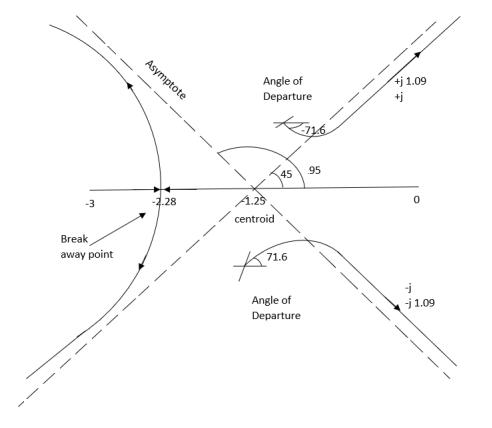
Fig. Root Locus for G(s) = 
Q6) Sketch the root locus for open loop transfer function. G(S) = K(S + 6)/S(S + 4)
A6)
- Number of zeros = 1(S = -6)
Number of poles = 2(S = 0, -4)
2. As P > Z one branch will terminate at infinity and the other at S = -6.
3. For Break away and breaking point
1 + G(S)H(S) = 0
1 + K(S + 6)/S(S + 4) = 0
Dk/ds = 0
S2 + 12S + 24 = 0
S = -9.5, -2.5
Breakaway point is at -2.5 and Break in point is at -9.5.
4. Root locus will be in the form of a circle. So finding the centre and radius. Let S = + jw.
G( + jw) = K( + jw + 6)/( + jw)( + jw + 4 ) = +- π
Tan-1 w/ + 6 - tan-1 w/ – tan-1 w / + 4 = - π
Taking tan of both sides.
w/ + w/ + 4 / 1 – w/ w/ + 4 = tan π + w / + 6 / 1 - tan π w/ + 6
w/ + w/ + 4 = w/ + 6[ 1 – w2 / ( + 4) ]
(2 + 4)( + 6) = (2 + 4 – w2)
2 2 + 12 + 4 + 24 = 2 + 4 – w2
22 + 12 + 24 = 2 – w2
2 + 12 – w2 + 24 = 0
Adding 36 on both sides
( + 6)2 + (w + 0)2 = 12
The above equation shows circle with radius 3.46 and center (-6, 0) the plot is shown in figure.
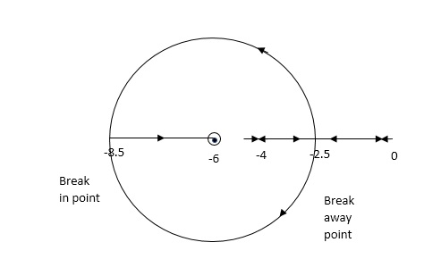
Fig. Root locus for G(S) = K (S + 6)/S (S + 4)
Q7) Determine the stability of the system represent by following characteristic equations using Routh criterion
1) S4 + 3s3 + 8s2 + 4s +3 = 0
2) S4 + 9s3 + 4S2 – 36s -32 = 0
A7)
1) S4+3s3+8s2+4s+3=0
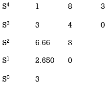
No sign change in first column to no rows on right half of S-plane system stable.
S4+9S3+4S2-36S-32 = 0
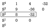
Special case II of Routh Hurwitz criterion forming auxiliary equation
A1 (s) = 8S2 – 32 = 0
 = 16S – 0 =0
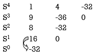
One sign change so, one root lies on right half S-plane hence system is unstable.
Q8) For using feedback open loop transfer function G(s) = 
Find range of k for stability
A8) Findlay characteristics equation.
CE = 1+G (s) H(s) = 0
H(s) =1 using feedback
CE = 1+ G(s)
1+  = 0
= 0
S(S+1)(S+3)(S+4)+k = 0
(S2+5)(S2+7Sα12)αK = 0
S4α7S3α1252+S3α7S2α125αK = 0
S4+8S3α19S2+125+k = 0
By Routh Hurwitz Criterion
S4 1 19 K
S3 8 12 0
S2 17.5 K
S1  0
0
S0 k
For system to be stable the range of K is 0< K <  .
.
Q9) The characteristic equation for certain feedback control system is given S4 +4S3+ 12S2+36S+K. Find range of K for system to be stable.
A9)

S4+4S3α12S2+36SαK = 0
For stability K>0
 > 0
> 0
K < 27
Range of K will be 0 < K < 27
Q10) Check if all roots of equation S3+6S2+25S+38 = 0, have real poll more negative than -1.
A10)

No sign change in first column, hence all roots are in left half of S-plane.
Replacing S = Z-1. In above equation
(Z-1)3+6(Z-1)2+25(Z-1)+38 = 0
Z3+ Z23+16Z+18=0

No sign change in first column roots lie on left half of Z-plane hence all roots of original equation in S-domain lie to left half 0f S = -1
Q11) The open loop transfer function of a system with unity feedback gain G(S) = 20 / S2 + 5S + 4. Determine the ξ, Mp, tr, tp.
A11)
Finding closed loop transfer function,
C(S) / R(S) = G( S ) / 1 + G( S ) + H( S )
As it is unity feedback so, H(S) = 1
C(S)/R(S) = G(S)/1 + G(S)
= 20/S2 + 5S + 4/1 + 20/S2 + 5S + 4
C(S)/R(S) = 20/S2 + 5S + 24
Standard equation for second order system,
S2 + 2ξWnS + Wn2 = 0
We have,
S2 + 5S + 24 = 0
Wn2 = 24
Wn = 4.89 rad/sec
2ξWn = 5
(a). ξ = 5/2 x 4.89 = 0.511
(b). Mp% = e-∏ξ / √1 –ξ2 x 100
= e-∏ x 0.511 / √1 – (0.511)2 x 100
Mp% = 15.4%
(c). tr = ∏ - φ / Wd
φ = tan-1√1 – ξ2 / ξ
φ= tan-1√1 – (0.511)2 / (0.511)
φ = 1.03 rad.
tr = ∏ - 1.03/Wd
Wd = Wn√1 – ξ2
= 4.89 √1 – (0.511)2
Wd = 4.20 rad/sec
tr = ∏ - 1.03/4.20
tr = 502.34 msec
(d). tp = ∏/4.20 = 747.9 msec
Q12) A second order system has Wn = 5 rad/sec and is ξ = 0.7 subjected to unit step input. Find (i) closed loop transfer function. (ii) Peak time (iii) Rise time (iv) Settling time (v) Peak overshoot.
A12)
The closed loop transfer function is
C(S)/R(S) = Wn2 / S2 + 2ξWnS + Wn2
= (5)2 / S2 + 2 x 0.7 x S + (5)2
C(S)/R(S) = 25 / S2 + 7s + 25
(ii). tp = ∏ / Wd
Wd = Wn√1 - ξ2
= 5√1 – (0.7)2
= 3.571 sec
(iii). tr = ∏ - φ/Wd
φ= tan-1√1 – ξ2 / ξ = 0.795 rad
tr = ∏ - 0.795 / 3.571
tr = 0.657 sec
(iv). For 2% settling time
ts = 4 / ξWn = 4 / 0.7 x 5
ts = 1.143 sec
(v). Mp = e-∏ξ / √1 –ξ2 x 100
Mp = 4.59%
Q13) The open loop transfer function of a unity feedback control system is given by G(S) = K/S(1 + ST)
Calculate the value by which k should be multiplied so that damping ratio is increased from 0.2 to 0.4?
A13)
C(S)/R(S) = G(S) / 1 + G(S)H(S) H(S) = 1
C(S)/R(S) = K/S(1 + ST) / 1 + K/S(1 + ST)
C(S)/R(S) = K/S(1 + ST) + K
C(S)/R(S) = K/T / S2 + S/T + K/T
For second order system,
S2 + 2ξWnS + Wn2
2ξWn = 1/T
ξ = 1/2WnT
Wn2 = K/T
Wn =√K/T
ξ = 1 / 2√K/T T
ξ = 1 / 2 √KT
Forξ1 = 0.2, for ξ2 = 0.4
ξ1 = 1 / 2 √K1T
ξ2 = 1 / 2 √K2T
ξ1/ ξ2 = √K2/K1
K2/K1 = (0.2/0.4)2
K2/K1 = 1 / 4
K1 = 4K2
Q14) Consider the transfer function C(S)/R(S) = Wn2 / S2 + 2ξWnS + Wn2
Find ξ, Wn so that the system responds to a step input with 5% overshoot and settling time of 4 sec?
A14)
Mp = 5% = 0.05
Mp = e-∏ξ / √1 –ξ2
0.05 = e-∏ξ / √1 –ξ2
Cn 0.05 = - ∏ξ / √1 –ξ2
-2.99 = - ∏ξ / √1 –ξ2
8.97(1 – ξ2) = ξ2∏2
0.91 – 0.91 ξ2 = ξ2
0.91 = 1.91 ξ2
ξ2 = 0.69
(ii). ts = 4/ ξWn
4 = 4/ ξWn
Wn = 1/ ξ = 1/ 0.69
Wn = 1.45 rad/sec
Q15) For the OLTF with unity feedback is G(s)=  . Determine the damping ratio, maximum overshoot, rise time?
A15) T
He CLTF will be T(s) = 
T(s) = 
For second order system,
S2 + 2ξWnS + Wn2
wn =  = 5.1
= 5.1
2ξWn = 5
i) Damping Ratio  = 0.49
Ii) Maximum overshoot Mp = e-∏ξ / √1 –ξ2 x 100
= e-∏x0.49 / √1 –(0.49)2
= 17.1%
Iii) Rise Time tr = ∏ - φ/Wd
Wd = Wn√1 - ξ2
= 5.1 √1 – (0.49)2
= 4.45 sec
φ= tan-1√1 – ξ2 / ξ = 1.059 rad
tr = ∏ - φ/Wd
= ∏ - 1.059/4.45
=468.53msec
Q16) Using Routh criterion determine the stability of the system with characteristic equation S4+8S3+18S2+16S+S = 0
A16)
Arrange in rows.
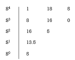
For row S2 first element
S1 =  = 16
= 16
Second terms =  = 5
= 5
For S1
First element =  = 13.5
For S0
First element =  = 5
= 5
As there is no sign change for first column so all roots are is left half of S-plane and hence system is stable.
Special Cases of Routh Hurwitz Criterions
- When first element of any row is zero.
In this case the zero is replaced by a very small positive number E and rest of the array is evaluated.
Eg.(1) Consider the following equation
S3+S+2 = 0
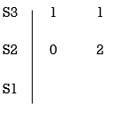
Replacing 0 by E
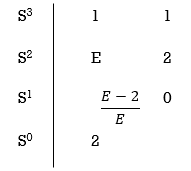
Now when E  0, values in column 1 becomes

Two sign changes hence two roots on right side of S-plans
Q17) Using Routh criterion determine the stability of the system with characteristic equation S3 + 5S2 + 6S + 30
A17)
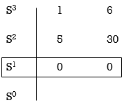
For forming auxiliary equation, selecting row first above row hang all terms zero.
A(s) = 5S2 e 30
 = 10s e0.
Again forming Routh array

No sign change in column one the roots of Auxiliary equation A(s)=5s2+ 30-0
5s2+30 = 0
S2 α 6= 0
S = ± j 
Both lie on imaginary axis so system is marginally stable.
Q18) Find the initial value for the function f(t) = 2u(t)+3cost u(t)?
A18)
f(t) = 2u(t)+3cost u(t)
F(s) = 
SF(s) = 2+ 
By initial value theorem
 = f(0+)
 =
=  2+
2+  = 5 = f(0+)
Hence, initial value of the function is 5
Q19) Find final value of the function F(s) = 
A19)
F(s) = 
SF(s) = 
By final value theorem
 =
= 
 =
=  = 0.1
= 0.1
So, final value of the function is 0.1
Q20) With help of waveform explain all the standard test signals?
A20) The Impulse signal, Ramp signal, unit step and parabolic signals are used as the standard test signals. All these signals are explained below.
Impulse Signal: -
This signal has zero amplitude everywhere except at the origin. Fig below shown the representation of Impulse signal.

Fig. Unit Impulse Signal
The mathematical representations
A (t) = 0 for t ≠0
 dt = A e
Where A represent energy or area of the Laplace Transform of Impulse signal is
L [A (t)] = A
UNIT IMPULSE SIGNAL: -
If A = 1
 (t) = 0 for t ≠0
L [ (t)] = 1
The transfer function of a linear time invariant
System is the Laplace transform of the impulse response of the system. If a unit impulse signal is applied to system, then Laplace transform of the output c(s) is the transfer function G(s)
As we know G(s) = c(s)/R(S)
r(t) =  (t)
(t)
R(s) = L [ (t)] = 1
:. G(S) = C(s)
(b) Step signal: -
Step signal of size A is a signal that change from zero level to A in zero time and stays there forever.
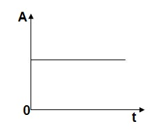
Fig. Unit Step Signal
r(t)= A t >=0
=0 t<0
L[r(t)] = R(s) = A/s
UNIT STEP SIGNAL: - If the magnitude of the slip signal is I then it is called unit step signal.
u(t) = 1
t>=0
t<0
L[u(t)] = 1/s
(c) Ramp Signal: -
The vamp signal increase linearly with time from initial value of zero at t= 0 as shown in fig is below

Fig. Ramp Signal
r(t) = At t>=0
=0 t<0
A is the slope of the line The Laplace transform of ramp signal is
L[r(t)] = R(s) = A/s2
(d) Parabolic Signal: -
The instantaneous value of a parabolic signal varies as square of the time from an initial value of zero t=0. The signal representation in fig 14 below.
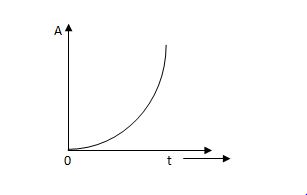
Fig. Parabolic Signal
r(t) At2 t>=0
=0 t<0
Then Laplace Transform is given as
R(s) = L[At2] = 2A/s3
If no error then E(t) =0, R(t) = c(t), output is tracking the input.
Steady state Errors signal (ess): - (t  )
)
Ess = t  e(t)
e(t)
Using final values, the theorem
 = ess =
  S.E (s)
ess=  S[R(s)/1+G/(s)]