Unit - 2
TEM mode in Co-ax line
Q1) What is TEM mode in Co-ax line.
A1) Coaxial cables are widely used in laboratories and carry signals in the TEM mode.
• At higher frequencies, the dimensions of the cables should be however limited as higher order modes (with a cut-off) can propagates
• This in turn limits the power capability
• Coaxial cables are typically utilized below 3 GHz with attenuation losses of a few dB/100m in the UHF range (around 100 MHz)
• Losses however quickly rise with frequency (for small cables to ~10 dB/100m at 1 GHz) with an average power rating around just 1kW.
• The main losses arise due to the skin effect in the inner conductor, which is technically more difficult to cool than the outer conductor
• At higher frequencies (around 10 GHz) the dielectric losses of the insulator can become dominant • By enlarging the coaxial lines diameters (several inches for outer diameter), the power capability may rise above 100 kW (at few hundred MHz) and into the MW regime (at few 10 MHz) with small attenuation losses (< 1dB/100m).
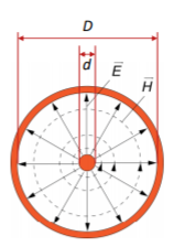
Fig 1 TEM Mode
The coax line wave impedance is given by
Z=  Ln (
Ln ( )
)
Z  Ln (
Ln ( )
)
Z0  120π
120π
Q2) Explain cylindrical waveguide Dominant Mode.
A2) A circular waveguide is a tubular, circular conductor. A plane wave propagating through a circular waveguide results in transverse electric (TE) or transverse magnetic field (TM) mode. Assume the medium is lossless(α=0) and the walls of the waveguide is perfect conductor(σ=∞).
The field equations from MAXWELL’S EQUATIONS are:
∇xE=-jωμH ------(1.a)
∇xH=jωϵE -----(1.b)
Taking the first equation, ∇xE=-jωμH
Expanding both sides of the above equation in terms of cylindrical coordinates, we get

Equating


Similarly expanding 

Equating


Let us assume that the wave is propagating along z direction. So


And


Let 
For lossless medium 
Now the final equation for E is


Q3) Explain the design of Cylindrical Waveguide to support Dominant TE11 mode.
A3) For TE mode, Ez=0, Hz≠0. As the wave travels along z-direction, e −γz is the solution along z-direction. As


According to maxwell’s equation, the laplacian of Hz:


Expanding the above equation, we get

Now, 

Putting this value in the above equations, we get


Applying boundary conditions
At 


If the roots of above equation are defined as  then
then


Cut off frequency
It is the minimum frequency after which the propagation occurs inside the cavity
But we know that 


Q4) Write short note on Microwave Resonator
A4) Basically, resonators are used for storing energy. At very high frequencies, the RLC circuit elements are inefficient when used as resonators because the circuit dimensions are comparable with the operating wavelength. Due to this, unwanted radiation takes place. Hence at high frequencies, the RLC resonant circuits are replaced by electromagnetic resonant cavities. When a perfectly conducting plane is used to close the wave guide, along the axis of propagation, a standing wave pattern is produced. At the end walls, the tangential component of the electric field intensity is zero. The electric field intensity will be zero at a half wavelength back along the guide. As the electric field is zero at any half wave point, we can introduce a conducting plane at every such points without changing field configurations.
Thus in between the two conducting planes, an exciting antenna can be realized then. Thus in between two planes we can have a cavity produced which shows properties of parallel resonant circuit. Hence when one end of the waveguide is terminated in short circuit, the reflections of the waves take place, which results in the generation of standing waves. Consider a section of a rectangular waveguide with both the ends terminated by a shorting plate. When the short plate is inserted at a distance equal to the multiplies of λg/2, a cavity is produced.
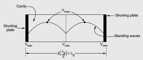
Fig 2 Waveguide
The waveguide section from which the cavity resonator is constructed may be either rectangular or circular. So, depending upon the type of waveguide, we can have rectangular cavity and circular cavity resonator.
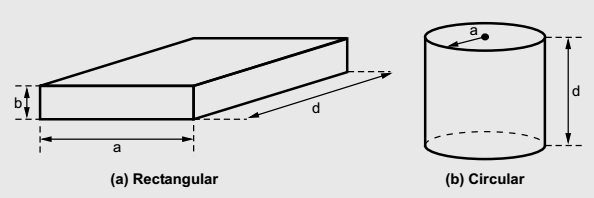
Fig 3 Cavity Resonator
The cavity resonators are used as tuned circuits. The cavity resonators are also used in UMF tubes, klystron amplifier, oscillators, duplexes of radar. The circular cavity resonators are also used in microwave frequency meter.
In general, the rectangular waveguides are constructed from closed sections of the waveguide, as the waveguide is the type of the transmission line. Usually, the rectangular waveguide resonators are short circuited at both the ends to avoid the radiation losses from open end of the waveguide. Due to short circuited ends of the
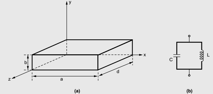
waveguide, a cavity or closed box is formed. Within this cavity, both the energies, electric and magnetic are stored. The power dissipation is observed at the metallic, conducting walls of the waveguides as well as in the dielectric inside the cavity. Through a small aperture or a small probe or a loop such resonators are coupled. The geometry of the rectangular cavity resonator is as shown in the figure below,
The guide wavelength is given by,
 (1)
(1)
The most dominant mode in the rectangular waveguide is TE10 mode. Basically, for the dominant mode, the resonant frequency of the field configuration is lowest. For TE10mode, λc= 2a. Hence guide wavelength is given by,

From equation (2) it is clear that, dimension 'a' is fixed for the resonator. So also, the guide wavelength λg is fixed. But in general, the frequency is given by,
 (3)
(3)
As λ0 is fixed and c is velocity of light which is also constant, for the given mode, the frequency has fixed value denoted by f0. Thus the rectangular resonant cavity supports only one frequency for a given mode. This frequency is called resonant frequency and thus the cavity formed is called resonant cavity. This cavity resonator behaves similar to parallel LC resonant circuit commonly called tank circuits. The resonant frequency for such equivalent parallel circuit is given by,

Q5) Derive expression for Resonant frequencies and of Cavity Supporting Dominant mode
A5) Expression for Resonant Frequency(f0) for Rectangular Cavity Resonator
For the rectangular waveguide we have a relation given by,

therefore,
 (4)
(4)
But for a condition of a wave propagation, we can write,

 Hence equation (4) can be written as,

 (5)
(5)
But the condition for the cavity resonator is that the cavity must be an integer multiple of a half-guide wavelength long at the resonant frequency. Hence we can write,
 (6)
(6)
Here p is known as number of half wavelength variations of either electric or magnetic fields along z-direction. Thus depending on the value of p, the general wave mode through the cavity resonators are denoted by TEmnp for the transverse electric (TE) wave and TMmnp for the transverse magnetic (TM) wave. To have a resonator resonating at a fixed frequency, ω0, or f0,substituting value of β̅ from equation (6) in equation (5), we can write,


or,

But ω0 = 2πf0,
 (7)
(7)
We can modify this expression by taking π2 out of the radical term as π, and write,
 (8)
(8)
If the resonator cavity is filled with a air, then we can write,

where c = 3 x 10⁸ m/s = Velocity of light
Thus for free space within the cavity, the frequency of resonance is given by,
 (9)
(9)
Equations (8) and (9) indicate the resonant frequency of a rectangular cavity resonator with dimensions a, b and d for both TMmnp and TEmnp modes in it.
Q6) Explain principle of Excitation of waveguide and Resonators
A6) The methods for excitation are
Loop Excitation
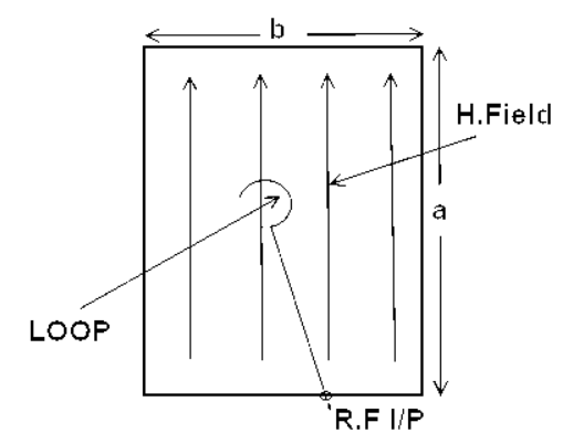
Fig 4 Loop Excitation
As shown in the figure the loop excitation is carried out in the cavity resonator by introducing the loop inside the cavity. The loop is inserted from the narrow dimension of the cavity and it should be kept at the place inside cavity where magnetic field is maximum.
When the RF signal is applied through the loop. The magnetic flux starts to expand and collapse around the loop. The magnetic flux causes to induce the voltage in the walls of cavity resonator. As the induced emf is the microwave signal, therefore, the oscillation action inside the cavity resonator takes place.
Probe Excitation
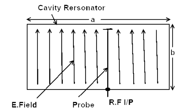
Fig 5 Probe Excitation
As shown in figure, the probe excitation is carried out in the cavity resonator by introducing the probe inside the cavity. The probe is inserted from the broad dimension of the cavity and it should be kept at the place inside the cavity where electric field is maximum.
When the RF is applied through the probe, the electric field starts to expand and collapse around the probe, this electric field causes to excite the cavity resonator and the oscillation inside the resonator takes place.
Aperture Excitation
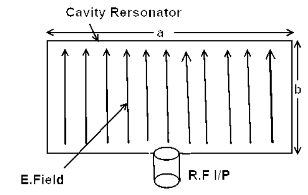
Fig 6 Aperture Excitation
As shown in figure above the aperture excitation is carried out by making the slot in the cavity resonator. In this case we couple the E-field or H-field to the cavity with the help of a circular or rectangular waveguide. The field causes to excite the cavity resonator. If the coupling is carried out from the broad dimension of cavity resonator, the operation will be TE mode. If we couple the input from the narrow dimension the operation will be in TM mode.
Q7) Explain Power Dividers
A7)
• Passive microwave components for power division or power combining Power division and combining. (a) Power division. (b) Power combining.
• Three-port networks: T-junctions and other power dividers (3dB or unequal)
Four-port networks: directional couplers (arbitrary) and hybrids (equal)
Hybrid junctions with phase shift (90 or 180 degree)
A power divider is used to split a signal.

Fig 7 Power Divider
General 3-port network:
[S] = 
If all three ports are matched, and the device is reciprocal and lossless, we have:
[S] = 
Lossless ⇒ [S] is unitary
Hence:
|S12|2 +|S13|2 =1
|S12|2 +|S23|2 =1
|S13|2 +|S23|2 =1
The above equations cannot be satisfied. At least 2 of S13, S12 and S23 must be zero.
S13S23*=0
S12S23*=0
S12S13*=0
Matching at ports 2 and 3 would be helpful when output lines 2 and 3 are not matched to their loads.
T-Junction: A lossless divider
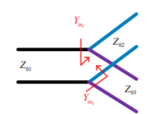
Fig 8 T junction

To match: 

Yin3  1/Z03
1/Z03
Yin2  1/Z02
1/Z02
Assuming port 1 matched:
Z01 = 
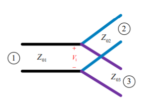
Fig 9 Two output lines


 =
= 
We can design the splitter to control the powers going into the two output lines.
Examine the reflection at each port (Sii):
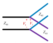
Fig 10 Voltage distribution at terminal 2,3


A match on port 1 requires: Z01<Z02, Z01<Z03, (The two output lines combine in parallel.)
Also, we have:


If port 1 is matched: Z01 = 


[S] = 

Q8) Explain basic properties of Directional Couplers
A8) The directional coupler is a 4–port reciprocal device. Direction couplers consist of two transmission lines and a mechanism for coupling signals between them.
A coupler is a device that consists of two waveguides which are placed very close to each other.

Fig 10 Directional coupler
A portion of energy traveling in waveguide A will be coupled on waveguide B.
The term directional means that the energy is passed in one direction only, and no energy passes in the reverse direction. The directional property is obtained by using a specific length (L) of a transmission line, that is, a quarter wavelength (λ/ 4). A λ/ 4 transmission line offers high impedance at one end and low impedance at the other end. The specific length (L = λ/ 4 or (2n + 1) λ/ 4) makes a coupler directional over a certain band of frequency.
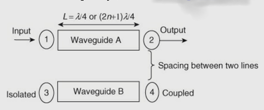
Fig 11 Spacing between waveguide
Power flow in a directional coupler:
The power incident at port 1 (input) is split between two other ports (port 4)
(coupled) and port 2 (output)), and no power appears from port 3 (isolated).

Pi or P1 = power incident at port 1
Pf or P2 = forward power or output power at port 2
Pb or P3 = reflected power at isolated port 3 in secondary waveguide
Pfc or P4 = forward coupled power in the secondary waveguide, that is, at port 4.
The properties of an ideal directional coupler are as follows:
In an ideal directional coupler, all the four ports are perfectly matched and also ports1,3 and ports 2, 4 are perfectly isolated.
A portion of the wave is coupled to port 4 but not coupled to port 3 which is traveling from port 1 to port 2. Similarly, a portion of the wave travelling from port 2 to port 1 is coupled to port 3 but not to port 4.
Likewise, the portion of the wave traveling from port 4 to port 3 is coupled to port 1 but not to port 2. Similarly, a portion of the wave traveling from port 3 to port 4 is coupled to port 2 but not to port 1.
The coupling between port 1 and port 4 is similar to that between port 2 and port 3, and the degree of coupling depends on the structure of the coupler.
The outputs are always in phase quadrature; that is, they exhibit a phase difference of 90 degrees. For this reason, a directional coupler is called a quadrature-type hybrid.
Types of directional couplers:
There are two types of directional couplers; both are four-port components and are reciprocal. They are:
Two-hole directional coupler and,
Single-hole or Bethe-hole directional coupler
Parameters that Characterize the Directional Coupler:
A directional coupler is characterized by 3 parameters:
Coupling factor (C): It indicates the fraction of input power coupled to the coupled port.
Directivity (D): Directivity is the ability to isolate coupled (port 4) and backward (port 3) ports.
Isolation (I): Isolation is defined as the ratio of power incident to the power coupled in the isolated port and is expressed in dB.
Q9) Explain briefly the T-Junction Power Divider.
A9)
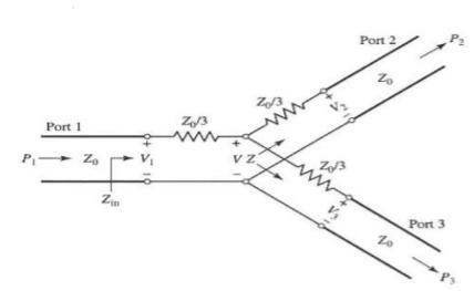
Fig 13 T-junction Power Divider
It is a junction of 3 transmission lines
In this case, if P1 is the input port power then P2 and P3 are the power of output Port2 and Port-3 respectively.
To transfer maximum power from port-1 to port-2 and port-3 the impedance must match at the junction.
For maximum power transfer Z01= Z02 || Z03
1/Z01= 1/Z02 + 1/Z03 (Condition for lossless power division)
Q10) What are Waveguide Directional Couplers.
A10)
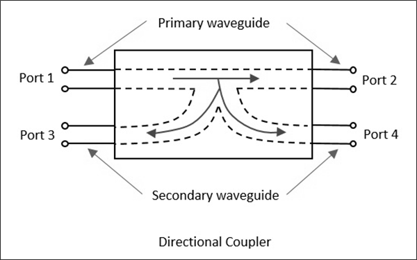
Fig 14 Directional Coupler
It is a 4- port waveguide junction consisting of a primary waveguide 1-2 and a secondary waveguide 3-4.
When all the ports are terminated in their characteristic impedance there is free transmission of power without reflection between port-1 and port-2 and no power transmission takes place between port-1 and port-3 or port-2 and port-4 a sno coupling exists.
The characteristic of a directional coupler is expressed in terms of its coupling factor and directivity.
The coupling factor is the measure of ratio of power levels in primary and secondary lines.
Directivity is the measure of how well the forward travelling wave in the primary waveguide couples only to a specific port of the secondary waveguide.
In ideal case, directivity is infinite i.e., power at port-3 =0 because port-2 and port-4 are perfectly matched.
Let wave propagates from port-1 to port-2 in primary line then:
Coupling Factor (dB) = 10 log10(P1/P4)
Directivity (dB) = 10 log10(P4/P3)
Where:
P1=power input to port-1
P3=power output from port-3 and
P4=power output from port-4
Q11) What are Fixed and Precision Variable Attenuator.
A11) An attenuator is a passive device that is used to reduce the strength or amplitude of a signal. At microwave frequencies, the attenuators were not only meant to do this, but also meant to maintain the characteristic impedance (Zo) of the system.
If the Zo of the transmission line is not maintained, the attenuator would be seen as impedance discontinuity, which causes reflections. Usually, a microwave attenuator controls the flow of microwave power by absorbing it. Attenuation in dB of a device is ten times the logarithmic ratio of power flowing into the device (Pi) to the power flowing out of the device (Po) when both the input and output circuits are matched.
Attenuation in dB = 10 log Pi /Po
In a microwave transmission system, the microwave power transferring from one section to another section can be controlled by a device known as microwave attenuator. These attenuators operate on the principle of interfering with electric or magnetic or both the fields. A resistive material placed in parallel to electric field lines (of field current) will induce a current in the material, which will result in loss. Thus, attenuation occurs by heating of the resistive element. Attenuators may be of two types:
Fixed attenuators are used where a fixed amount of attenuation is needed. They also called pads. In this type of attenuator tapering is provided by placing a short section of a waveguide with an attached tapered plug of absorbing material at the end. The purpose of tapering is for the gradual transition of microwave power from the waveguide medium to the absorbing medium. Because of the absorbing medium, reflections at the media interface will be minimized. In a fixed attenuator, plug is nothing but a dielectric slab which has a glass slab with aqua dog or a carbon film coating. The pad is placed in such a way that the plane is parallel to the electric field. For this, two thin metal rods are used.
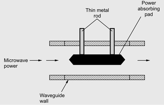
Fig 15 Fixed Attenuator
Variable attenuator provides continuous attenuation. The amount of attenuation
introduced is controlled by the depth of insertion of absorbing plate inside the waveguide. For this a knob and gear assembly are used. The knob can be calibrated suitably. The maximum attenuation will be offered when the pad extends all the way across the guide.
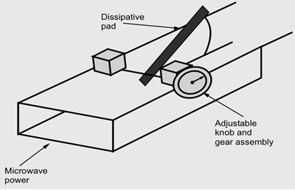
Fig 16 Variable Attenuator
The types of variable attenuators are:
Q12) Explain what is Ferrite and also explain about Fermle Isolator.
A12) A device that is composed of material which has useful magnetic properties and, simultaneously, it provides high resistance to current flow is a ferrite. The electron movement within the atoms of the material results in the magnetic property of that material. There are two types of motions of Electrons:
(1) Orbital movement of the electrons around the nucleus of the atom;
(2) Movement of the electron about its own axis, called electron spin. The different types of electron movement are shown in the figure below. Movement of the electrons within the atom causes the current to flow.
Therefore, the magnetic field is generated. Under the influence of the applied external magnetic field, the electron spin axes within some materials, such as iron or nickel, can be caused to align. Therefore, magnetic fields get added.
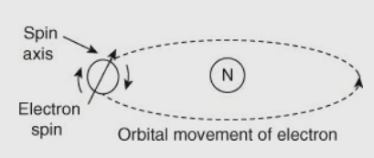
Fig 17 Generation of Magnetic Field
In the case of ferrites, electrons try to balance between two forces. They are as follows:
(1) A force that holds the atoms together (i.e., orbital motion of the electrons about the nucleus);
(2) An external static magnetic field. Interaction of these two forces causes the electrons to wobble on their axis (as shown in figure below).
Ferrite action depends on the behaviour of electrons due to the influence of the external field. This result is wobble frequency. Electrons that wobble also have natural resonant wobble frequency. It varies with the strength of the applied field.

Fig 18 Motion of electron according to applied electric field
Q13) Explain Principle of Operationing.
A13) An isolator is a unilateral, two-port nonreciprocal transmission device. It is used to isolate one component from reflections of other components in the transmission line. The flow of power can be from input to output, but cannot be the other way. Hence, the bad effects of changing load impedance can be reduced by the use of the isolator on a signal source. Ferrites are used as the main material in isolators. The function of an isolator is shown in the figure below,

Fig 19 Function of Isolator
An ideal isolator is one which absorbs the power fully for propagation in one direction and provides lossless transmission in the opposite direction. In the figure, the microwave energy is fed through port 1 of the isolator, and a load is connected through port 2 of the isolator.
The isolator allows the energy to travel through it and to reach the load with minimum attenuation and provides maximum attenuation to the energy travelling from load to source. Therefore, isolators are used to improve the frequency stability of the microwave generators, such as klystrons and magnetrons, in which the reflection from the load affects the generating frequency.
The figure below shows the Faraday rotation isolator. The isolator consists of a piece of circular waveguide supporting the dominant TE11 mode with transitions to a standard rectangular guide supporting the TE10 mode at both ends. A thin pencil-shaped ferrite is located inside the circular guide, supported by polyfoam, and the waveguide is surrounded by a permanent magnet that generates a magnetic field in the ferrite core.
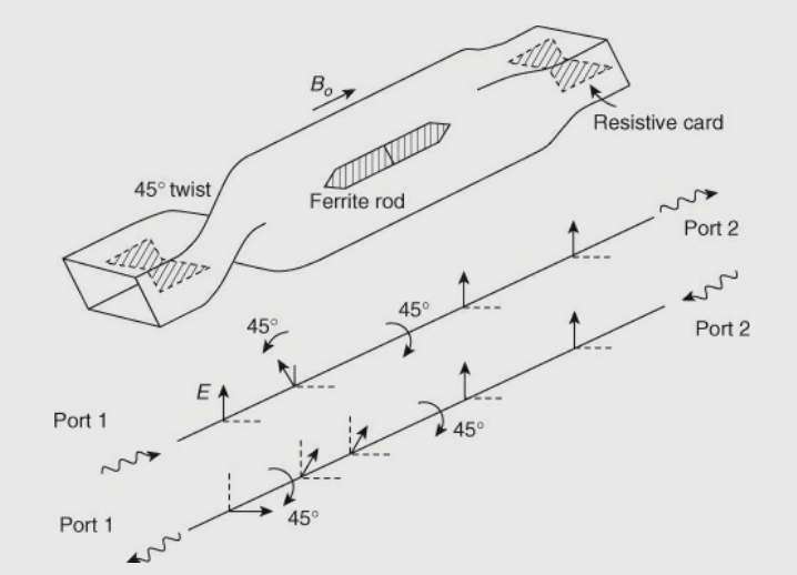
Fig 20 Magnetic Field in Ferrite core
Two resistive plates are placed in x-z plane at the ends of rectangular waveguide as shown in the figure. The transition from rectangular to circular waveguide results in 45° phase shift. The plane of polarization of the wave can be rotated by 45° by the DC magnetic field, which is applied longitudinally to the ferrite rod. The degree of rotation depends on the applied dc magnetic field and on the length and diameter of the ferrite rod.
If TE10 wave is incident on the isolator’s left end which is perpendicular to the input resistive card, then the wave passes through the ferrite rod without attenuation. The operation of isolator based on Faraday rotation is explained below. A TE10 wave passes from port 1 through the resistive card without attenuation. The wave is shifted by 45° due to twist in the anti-clockwise direction after coming out of the card. Then, because of the ferrite rod, there is a shift of another 45° in the clock-wise direction.
Hence, the polarization of the wave at port 2 will be same as at port 1 where there is no attenuation. As the plane of polarization of the wave is perpendicular to the plane of the resistive card, when the TE10 wave is fed from port 2, it passes from the resistive card placed near port 2. This wave suffers a phase shift of 45° in clock-wise direction due to the ferrite rod and again rotates by 45° in the same direction due to the twist.
Now, the input card absorbs the wave as the plane of polarization of the wave is parallel to the input resistive card. Therefore, zero output will appear at port 1. In reverse transmission, the typical performance of these isolators is about 20 to 30 dB isolation and in forward transmission is about 1 dB insertion loss.
Q14) Explain Faradays Rotation based circulator?
A14) The most important ferrite component is a circulator. A circulator is conceptually similar to the isolator, except that it is a multiport device. The circulator is also a unilateral device; i.e., power flows in only one direction. The main application of the circulator is in connection with multiple isolation in radars, parametric amplifiers, and so on.
It is a nonreciprocal device in which the ports are arranged in such a way that the electromagnetic energy which is entering a certain port is coupled to an adjacent port and not coupled to the other ports. The three-port symmetrical devices are commonly used as circulators. The figure below represents a three-port circulator’s circuit symbol.

Fig 21 Circulator
A signal applied to port 1 emerges from port 2 with a loss if all ports of a circulator are matched. This loss is called the insertion loss, which is given in decibels is given by,
Insertion Loss, IL (dB) = 10log10(
A small part of the input signal emerges from port 3. Assuming that port 2 is terminated by a matched load Isolation can also be defined as the ratio of that emerging signal to the input signal. Isolation is given in decibels as below.
I(dB) = 10 log10(
The circulator is a three-port network that can be used to prevent reflection at the antenna from returning to the source