Unit – 2
Biaxial State of Stress and Strain
Q1) Explain biaxial State of Stress and Strain: Analysis of Biaxial Stress?
A1)
Biaxial State of Stress
A -dimensional kingdom of pressure wherein most effective ordinary stresses are gift is referred to as biaxial pressure. Likewise, a one-dimensional kingdom of pressure wherein ordinary stresses act alongside one route most effective is referred to as a uni axial pressure kingdom.
Biaxial State of Strain
Biaxial strain" in preferred manner that during of the 3 impartial spatial directions (Cartesian system) there are mechanical clamping mechanisms gift in order that an elastic rest can simplest arise within side the 1/3 direction
The extra preferred strain situation wherein the stresses on an element acts in each x and y guidelines and all strain additives in z- direction vanish is known as biaxial strain system. It is different from one dimensional or uni axial strain situation considered in the previous section.
Thus it is assumed that all the additives in the z-direction yz = σz =0)xz = are zero. The strain element proven in is obtained; it's miles the maximum preferred situation that can exist. Biaxial stresses get up within side the evaluation of beams, stress vessels, shafts and lots of different structural members.
A magnificence of not unusual place engineering issues related to stresses in a thin plate or loose floor of a structural element, inclusive of the surfaces of thin walled pressure vessels beneath external or internal pressure, the loose floor of shafts in torsion or beams beneath transverse loads.
General case of dimensional pressure In general if a aircraft element is removed from a body it will be subjected to the everyday stresses σx and σy collectively with the shearing pressure xy as . It is desirable to investigate the kingdom of pressure on any willing aircraft t described with the aid of using attitude θ, fantastic ccw as The ensuing members of the family might make it feasible to determine normal strain σn and the shear strain on the willing plane t shape ordinary n to the willing aircraft t shape information of ordinary and shear stresses at the X and Y planes (typically known). Note that the ordinary n to the willing aircraft t make an perspective θ with the x-axis. This perspective θ is taken into consideration to be wonderful while measured within side the ccw route from the wonderful cease of the x-axis.
According to signal convention, that is the one used all through this text, a shear strain is wonderful if it produces clockwise rotation of the detail on which it's far performing and bad if it xyproduces counterclockwise rotation. Thus at the X plane in Figure is wonderful xywhile at the Y plane yx) is (i.e., poor. However, as changed into said earlier, ordinary stresses are superb if tensile and poor if compressive. Isolate the small wedge to the left of the willing aircraft and assemble its free-frame
If one assumes the place of the willing aircraft to be A rectangular units, then the place of the X aircraft could be A cos θ rectangular units and the place of the Y aircraft could be A sin θ rectangular units.
Thus the forces at the 3 faces of the wedge produced by the ordinary and shear stresses acting on them can be decided in phrases of A and the trigonometric features of the perspective θ.
Q2) What is Plane stress?
A2)
Plane pressure is described to be a state of pressure wherein the everyday pressure is zero and the shear stresses, O rz and O yz, directed perpendicular to the x-y plane are assumed to be zero.
In continuum mechanics, a material is said to be beneath plane pressure if the pressure vector is zero for the duration of a particular plane. When that situation occurs over an entire element of a structure, as is frequently the case for thin plates, the pressure assessment is notably simplified, due to the fact the pressure nation can be represented with the resource of the use of a tensor of length 2 (represent able as a 2 × 2 matrix in desire to 3 × 3).
A related notion, plane pressure, is frequently applicable to very thick members. Plane pressure typically occurs in thin flat plates which can be acted upon excellent with the resource of the use of load forces which can be parallel to them. In positive situations, a gently curved thin plate also can be assumed to have plane pressure for the reason of pressure assessment. This is the case, for example, of a thin-walled cylinder complete of a fluid beneath pressure. In such cases, pressure components perpendicular to the plate are negligible in contrast to those parallel to it
In unique situations, however, the bending pressure of a thin plate cannot be neglected. One can although simplify the assessment with the resource of the use of the usage of a two-dimensional domain, but the plane pressure tensor at each element ought to be complemented with bending terms.
Q3) What is Principal plane and Principal stress?
A3)
We have studied the effect of simple stresses which were either normal or tangential acting on particular plane only.
Most of cases on actual member, more complex condition of stresses are developed.
We study the analytical and graphical method to find the stresses acting on an inclined plane of the member subjected combined stresses.
The plane on which the normal stress or the shear stress reaches their maximum intensity has particularly significant on the materials.
1. Concept Principal Plane:
The plane on which only normal stresses acts and no shear stress is called principal plane.
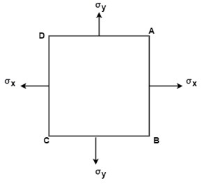
The plane AB, BC, CD and AD as shown in fig carries only normal stress and no shear stress. These planes are called as Principal planes.
2. Principal stress:
The magnitude of normal stress acting on the principal plane is called as principal stress.
3. Major Principal stress:
- It is maximum value of normal stress acting on the principal plane.
- It is the maximum intensity of direct stress.
4. Minor Principal Stress:
- It is minimum value of normal stress acting on the principal plane.
- It is the minimum intensity of direct stress.
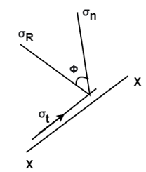
5. Major Principal Plane:
- A plane which carries major principal stresses is called as major principal plane.
6. Minor Principal Plane:
- A plane which carries the minor principal stress is called minor principal plane
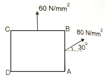
Q4) The intensity of the resultant stress, on a plane AB at a point in a material under stress is 80  /
/ and is inclined at
  to the normal to that plane. The normal components of stress on another plane BC, at right angles to the plane AB is 60 N/mm2 as shown in the Fig. Determine the following:
(i) The resultant stress on the plane BC.
(ii) The principal stresses and their directions.
(iii) The maximum shear stress and their planes.
A4)
Given:


Resultant stress on BC
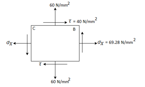

Principle stress


Directions of principle planes,


Maximum shear stress

Plane of maximum shear stress


Q5) An element in a two-dimensional stress system is subjected to normal stress intensity of  tensile along X-direction and
  compressive along Y-axis and shear intensity
  Determine the planes of zero shear and maximum shear. Also find the normal and shear stress intensity on these planes.
A5)
Given:


To find: 
(i) Plane of zero shear stress 


Location of principle


(ii) Plane of maximum shear stress


(iii) Normal Stress

For 


For 
(iv) Shear stress or tangential stress  and 100.9°

Q6) A rectangular block of a material is subjected to a tensile stress of 100 N/mm2 on one plane and a tensile stress of 50 N/mm2 on a plane at right angles, together with shear stresses of 60N/mm2 on the faces.Find1) The direction of principal planes 2)The magnitude of principal stresses 3) The magnitude of greatest shear test 4) The location of plane containing maximum shear stress.
A6)
Given

Case I. Direction of principle plane


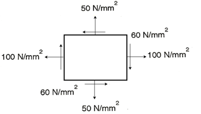
Case II: Magnitude of principal stress


Case 3: Magnitude of a greatest shear stress
 max=
max= =
= =65N/mm2
Case IV: Location of plane containing maximum shear

Q7) At a certain point in an elastic material, normal stresses of 96 MPa tensile and 75 MPa compressive are acting on planes at right angle to each other. The greater principal stress in the material is limited to 120 MPa. To what shearing stress may the material be subjected to on the given planes, and what will be the maximum shearing stress at that point.
A7)
Given:


To find: and 
(i) Shear stress


Squaring both side

(2) Maximum shear stress

Q8) At a point material, the values of normal stress across two angles to each other are 80 MPa and 32 MPa ,both tensile and there is a shear stress of 32MPa an shown in the Fig. Determine-
1) Stress component on the plane at  anticlockwise.
2) The Principal stress and their direction
3) The maximum shear stress
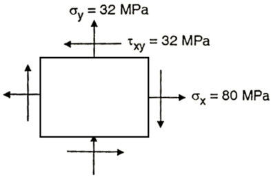
A8)
Given: 
To find: 
Principal stress


Major principal stress 
Minor principal stress 
Location of principal plane


Maximum shear stress 
Location of plane of maximum shear plane


Q9) For the stress condition on an element as shown Fig. Determine the principle planes and stresses. Also determine the maximum shear stress and the planes on which they act.
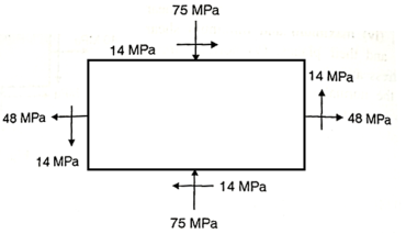
A9)
Given: 
To find: 
(i) Location of principal plane


Principle stress


Maximum Principle stress 
Minimum Principle stress 
(iii) Maximum shear stress

(iv) Location of shear plane


Q10) for the stress condition on an element as shown in Fig., determine the principal planes and stresses. Also determine the maximum shear stress anad the planes on which they act:
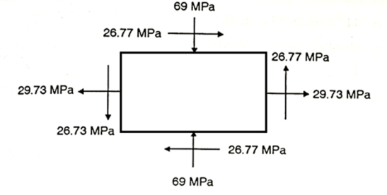
A10)
Given: 
To find: 
Principal planes


Principle stress


Maximum principal stress 
Minimum principal stress 
Maximum shear stress 
Location of plane of shear stress


Q11) Resultant stresses on two mutually perpendicular planes are as shown in Fig. Calculate principal stresses and their direction.
To find: 
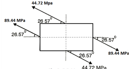
A11)
From the given Fig.(a) stress on the plane


 Location of principal plane


 Principal stress

Major principal stress 
Minor principal stress 
Q12) Direct stresses of 160N/m tensile and 120
  compressive exists on two perpendicular planes at a certain pint in a body. They are also accompanied by shear stresses on the planes. The greatest principal stress at the point due to there is 200
(i) What must be magnitude of shearing stresses on the two planes?
(ii) What will be the maximum shearing stress at the point.
A12)
Given:

To find: i) (ii) 
Major principal stress, 


Squaring both side, 

Maximum shear stress,

(ii) Alternative method for 
Minor principal stress


Maximum shearing stress,

Q13) At a point in a material under stress, intensity of the resultant stresses on a certain plane is  (tensile), inclined at
  to the normal of that plane. The stress on a plane right angle to it has a normal tensile component of 3
 . Find
(i) The resultant stress on the second plane
(ii) The principle plane and stresses
(iii) The plane of maximum shear stress and its intensity.
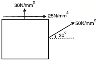
A13)
Given: 

To find: Result stress on the second plane, principal stress and maximum shear stress.
(i) Resultant stress on second plane

 Resultant stress,
(ii) Location of principle plane:


 Principle stress


 Major principle stress
 Minor principle stress
(iii) Maximum shear stress

Location of plane of maximum shear stress,


Q14) A plane element in a body is subjected to a tensile normal stress of 25MPa in X-direction and anticlockwise shear stress 100 MPA. Calculate the stresses on a plane inclined at 20° clockwise to X-axis.
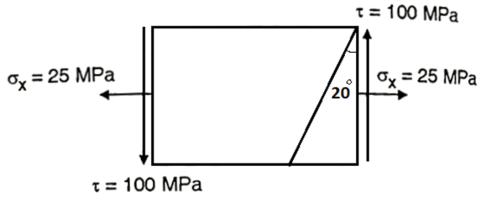
A14)
Given:


To find: 
Normal stress 
 =12.5+9.576-64.28

Tangential stress


Resultant stress


Angle of obliquity

Q15) For the given state of plane strain  . Determine
(i) Principle axis of strains
(ii) Principle strains
(iii) Maximum shearing strain
A15)
Given:

To find θ, 
(i) Principal axis of strain


(ii) Principal axis of strain


(iii) Maximum shear strain

Q16) Explain Mohr's Circle for Biaxial Stress?
A16)
A graphical method of finding of principle stresses normal longitudinal and resultant stresses with the help of circle is called as Mohr’s circle method
In this method direct stress ( ) is represent on x axis and shear stress (
 ) on y axis
Tensile direct stress is taken on positive x- axis and compressive direct stress on negative x- axis
Shear stress produced clockwise moment in the elements is consider positive and anticlockwise moment is negative
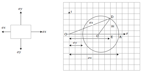
Centre of circle is found by 
Where  are dierect stresses
Radius of circle 
In Mohr’s circle the angle between the planes will be represented by double the angle
For example when circle draw from center c with radius R it cuts x- axis at point A and B where shear stress is zero
The angle between AOB is equal to 180 degree
But angle between two principle plans is 90 degree
At point A and B since, there is no shear stress OA and OB represents principle stresses
Radius of circle indicates the maximum shear stress which is located at 2 w.r.to x- axis i.e. at 2 x 45 degree = 90 degree
Q17) What is two dimensional state of strain?
A17)
A two -dimensional pressure (stress) system is one wherein the stresses at any factor in a frame act within side the same aircraft. Consider a skinny square block of material, abcd, faces of which can be parallel to the xy-plane
Stress within side the Lithosphere – iso static equilibrium (or Archimedes principle). In the mantle below the lithosphere, stress ought to be equal. Thus, the burden of the overlying rocks ought to be equal. The thick low density crust floats better at the as lithosphere. The continental crust is be neat anxiety due to the fact the pressure at any given intensity in the crust is better than within side the adjoining mantle. The low density crust needs to unfold out over the mantle.
Thrust Sheets - Shear pressure consequences from the frictional resistance to movement at the fault. Shear pressure is associated with the burden of overburden and the coefficient of friction.
Stress in Two Dimensions - State of pressure in 2D may be defined through ordinary stresses and 1 shear pressure (the 2 shear stresses ought to be equal or the frame might rotate).
Normal and shear pressure on any arbitrary aircraft may be decided from the 2 ordinary stresses (x- and y-axes) and one shear pressure and the attitude among the ordinary to the plane and the x-axis.
Principal axes of pressure are ordinary to planes of 0 shear pressure. The important axes are orthogonal.
Maximum shear pressure is 45° from the important pressure direction. Maximum shear pressure is one 1/2 of the difference of the important stresses.
Q18) What is Principal strains?
A18)
Principal Strain:
Maximum and minimal normal strain feasible for a particular factor on a structural element
Shear strain is zero on the orientation where major strain occurs.
Principle strain is also known as st. Vanant theory
The principal strain causes that the material subjected to conjugate stresses will falls when the maximum principal strain in the reaches the value of strain at yield point in a simple tensile test at materials
Q19) What is Mohr's circle for strain?
A19)
A graphical method of finding of principle stresses normal longitudinal and resultant stresses with the help of circle is called as Mohr’s circle method
In this method direct stress ( ) is represent on x axis and shear stress (
 ) on y axis
Tensile direct stress is taken on positive x- axis and compressive direct stress on negative x- axis
Shear stress produced clockwise moment in the elements is consider positive and anticlockwise moment is negative
Centre of circle is found by 
Where  is direct stress
Radius of circle 
In Mohr’s circle the angle between the planes will be represented by double the angle
For example when circle draw from center c with radius R it cuts x- axis at point A and B where shear stress is zero
The angle between AOB is equal to 180 degree
But angle between two principle plans is 90 degree
At point A and B since, there is no shear stress OA and OB represents principle stresses
Radius of circle indicates the maximum shear stress which is located at 2 w.r.to x- axis i.e. at 2 x 45 degree = 90 degree
Q20) For the elements shown in fig. Locates the planes on which magnitude of the shear stress and nominal stress are equal. Shown the result on property oriented elements. Also find the principle stresses.
A20)
Given:


To Find:
Plane on which

Nominal stress


Shear stress


Location of the plane at which shear stress and nominal stress are equal


Q21) At a point in a strained material the normal and tangential stresses on a plane inclined at 40 degree to the plane carrying major principle stresses are 68 N/mm^2 and 158 N/mm^2 resp. Find the magnitude and nature of principle stresses. Also find the resultant stress on the given inclined plane.
A21)
Given:


To find:

Normal stress


Tangential stress


Solving equations


Q22) What is Strain Rosette?
A22)
A stress gauge rosette is a time period for an association of or extra stress gauges which are placed intently to degree traces alongside distinct guidelines of the aspect beneath evaluation.
Since for stress analysis in biaxial state of stress we should know stress in 3 instructions and because of drawbacks in a stress gauge, Strain rosettes got here in to picture. Strain rosette can be defined as the association of stress gauges in 3 arbitrary instructions.
These stress gauges are used to degree the regular stress in the ones 3 instructions. Depending at the association of stress gauges, stress rosettes are labeled in to:-
1. Rectangular stress gauge rosette
2. Delta stress gauge rosette
3. Star stress gauge rosette
Biaxial strain states arise very usually in machine parts and structural members, it might be presumed that half or so of the pressure gages used in experimental strain analysis would be rosettes.
This does not seem to be the case, however, and ten percent (or less) rosette utilization may also be extra almost representative. To what diploma this sample of utilization displays a bent for on-web page make-up of rosettes from single-detail gages, or definitely an undue tendency to expect uniaxiality of the strain state, is an open question.
At any rate, neither exercise can commonly be recommended for the correct willpower of primary strains. It must be appreciated that while the use of a pressure gage rosette is, in many cases, a necessary condition for obtaining the primary strains, it is not a sufficient condition for doing so accurately.
Knowledge ability in the choice and alertness of rosettes is vital to their successful use in experimental strain analysis; and the records contained on this Tech Note is supposed to help the person acquire reliably correct primary pressure data
Q23) Explain Thin Cylinder: Stresses in thin cylinders and thin spherical shells under internal pressure?
A23)
1. Thin cylinder
Thin cylindrical shell is likewise termed as a strain vessel and such vessels are typically utilized in numerous engineering applications along with for storing the fluid below strain.
Boilers, LPG cylinders, Air receiver tanks are the satisfactory examples of skinny cylindrical shells.
A cylindrical or round shell might be considered as skinny cylindrical or round shell, if the wall thickness of shell is very small compared to the inner diameter of the shell.
Wall thickness of a skinny cylindrical and round shell might be identical or much less than the 1/20 of the inner diameter of shell.
Hoop pressure
Stress appearing alongside the circumference of skinny cylinder might be termed as circumferential pressure or hoop pressure.
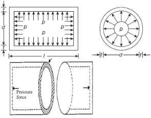
If fluid is saved below strain internal the cylindrical shell, strain might be appearing vertically upward and downward over the cylindrical wall.
Pressure vessel will have a tendency to burst as displayed right here in following parent and stresses advanced in such failure of cylindrical shell might be termed as circumferential pressure or Hoop pressure.
Cylindrical shell bursting will take location if pressure because of inner fluid strain could be extra than the resisting pressure because of circumferential pressure or hoop pressure evolved within side the wall of the cylindrical shell.
In order to stable the expression for circumferential pressure or hoop pressure evolved within side the wall of the cylindrical shell, we are able to must do not forget the restricting case i.e. pressure because of inner fluid strain have to be identical to the resisting pressure because of circumferential pressure or hoop pressure.
Force due to internal fluid pressure = Internal fluid pressure x Area on which fluid pressure will be acting
Force due to internal fluid pressure = P x (d x L)
Resisting force due to circumferential stress = σH x 2 L t
Force due to internal fluid pressure = Resisting force due to circumferential stress
P x d x L = σH x 2 L t
σH = P x d / (2 t)

Hoop stress developed in the wall of cylindrical shell.
P = Internal fluid pressure
d = Internal diameter of thin cylindrical shell
t= thickness of the wall of cylinder
L = Length of the cylindrical shell
σH = hoop stress developed in the wall of the cylindrical shell
2. Sphere subjected to internal pressures
Spherical shells are extensively used in lots of structural engineering applications inclusive of aerospace vehicles, roof domes, garage tanks, adaptive clever membranes and lively shells, laminated transducers and sensors, ballistic missile bulkhead and submarines
The round shell considered within side the gift study subjected to uniform temperature. The stress applied at the internal floor of the shell. The outer floor of the shell is loose from mechanical load. Thus, the boundary situations of the problem are given by
Trr = – p at r = a
Trr = 0 at r = b
Where,
Trr denote displacement and stress along the radial direction.
When a skinny cylindrical shell is subjected to an inner pressure, its wall be subjected to lateral strain, the impact of which there may be alternate in dimensions (i.e. duration and diameter) of the shell.
Stress performing alongside the duration of skinny cylinder will be termed as longitudinal stress.
If fluid is saved be neat stress internal the cylindrical shell, stress pressure could be performing alongside the duration of the cylindrical shell at its ends. Cylindrical shell will generally tend to burst as displayed right here in following parent and stresses evolved in such failure of cylindrical shell could be termed as longitudinal stress.
Longitudinal stress = (1/2) x Circumferential stress
σL = 1/2 x [p x d]/2t
σL = p.d/4t
Q24) What is wire winding of thin cylinders?
A24)
Wire winding of skinny cylinder is one manner to bolster a skinny walled tube towards an Internal Pressure is to wind the outdoor with twine beneath tension. This places the tube into compression and therefore reduces the Hoop Stress
Wire Winding Of Thin Walled Cylinders. This places the tube into compression and therefore reduces the Hoop Stress. In many programs the most Stress can be within side the wire, which have to be manufactured from high-tensile material
Storage tanks are containers that hold liquids, compressed gases or mediums used for the short or long term garage of heat or cold. The garage tanks like a strain vessels briefly described as “The fluids saved below strain or with out strain within side the vessel is referred to as a fluid tank or fluid cylinder. In this fluid tank is makes use of to save the compressed air are referred to as compressed fluid garage tank. In this garage tanks method in America or Britain is Reservoirs. The fluid tanks are designed with first-rate care due to the fact rupture of cylinder method an explosion which can also additionally reason lack of existence and property.
The fabric of cylinders can be brittle such that cast iron or ductile such as mild steel. In this fluid garage tanks or strain vessels are to be had in distinct shapes. They are Vertical Cylinder, Horizontal Cylinder and Wire wound cylinder. Wire wound cylinder is a sort of fluid tank cylinder.
Wire is wounded externally on the cylinder. There are sorts of cylinders. They are skinny and thick cylinders. If d/t<20 then it's far thick cylinder, d/t≥20 then it's far skinny cylinder. In skinny sorts of stresses are induced. They are Circumferential or Hoop strain and Axial or Longitudinal strain. One greater strain is induced i.e. radial strain but it is small so it is negligible. Three types of stresses induced in thick cylinder. They are Circumferential or Hoop strain, Axial or Longitudinal strain and Radial strain.