Unit – 3
Vapour Power Cycles
Q1) Explain the Carnot vapor cycle
A1) The Carnot cycle is the most efficient cycle operating between two specified temperature limits. Thus, it is natural to look at the Carnot cycle first as a prospective ideal cycle for vapor power plants.
However, the Carnot cycle is not a suitable model for power cycles.
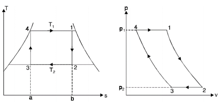
Thus, cycle is completed.
Net work done = Heat supplied – heat rejected
= T1 (s2 - s3) - T2 (s2 - s3)
= (T1 – T2) (s2 - s3)
Carnot Efficiency η = Work done / Heat supplied = (T1 – T2) (s2 - s3) / T1 (s2 - s3)
= (T1 – T2) / T1
Q2) What are the Limitations of Carnot Cycle:
A2) Though Carnot cycle is simple (thermodynamically) and has the highest thermal efficiency for given values of T1 and T2, still it is impossible to produce in actuality because:
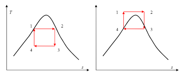
Some of these problems could be eliminated by executing the Carnot cycle in a different way, as shown in Fig.
Q3) Explain the Rankine cycle
A3) The above diagrams illustrate the various processes of a simple Rankine Cycle applied to a simple steam powered power plant.

Let us the various processes.
Process 1-2 Water is compressed in Pump till intake pressure of boiler. It is an isentropic compression process.
Q4) Explain the Analysis of Rankine Cycle
A4) Assume 1 kg of steam in the cycle and applying SFEE to various processes, we get,
for Process 1-2
Pump work = h2 - h1 = ʃ-V dp
for Process 2-3
Heat supplied in boiler (qi) = h3 - h2
For Process 3-4
Work done in turbine = WT= h3 - h4
For Process 4-1
Heat rejected in condenser (qr) = h4 – h1
Efficiency of Rankine Cycle (η)
Efficiency of Rankine Cycle η = (Shaft work) / (Heat supplied)
= WT – WP / qi
= {(h3 - h4) - (h2 - h1)} / h3 - h2
Methods of improving efficiency of Rankine Cycle
Q5) Explain the Rankine cycle efficiency
A5) Many of the impracticalities associated with the Carnot cycle can be eliminated by superheating the steam in the boiler and condensing it completely in the condenser. The cycle that results is the Rankine cycle, which is the ideal cycle for vapor power plants. The ideal Rankine cycle does not involve any internal irreversibility
1-2 isentropic compression in pump
2-3 constant pressure heat addition in a boiler
3-4 isentropic expansion in turbine
4-1 constant pressure heat rejection in condenser


(qin – qout)+(win –wout)=he-hi (KJ/Kg)
Pump (q=0) wpump.in=h2-h1
Wpump.in=v(P2-P1)
H1=hf@ p1 & v = v1= vf@ pi
Boiler (w=0) qin =h3-h2
Turbine (q=0) Wturb. Out =h3-h4
Condenser (w=0) qout = h4-h1
Wnetb= qin – qout = Wturbo.out-Wpump.in

Q5) Explain the Advantages of Reheat Cycles
A5) Reheated steam eliminated the erosion and corrosion to the blades of the turbine,
• Turbine output will be increased,
• ηth will be increased,
• Final dryness fraction is improved,
• Nozzle and blade efficiencies are increased, and
• Specific steam consumption is decreased.
Efficiency Calculation of Reheat Cycle: The total heat added per kg of steam
Q = (h1 – h5) + (h3 – h2) – wP kJ/kg
Work done = W = (h1 – h2) + (h3 – h4) – wP kJ/kg
where, wP = Pump work = h6 – h5
Efficiency of reheat cycle 
How can we take advantage of the increased efficiencies at higher boiler pressures without facing the problem of excessive moisture at the final stages of the turbine?
1. Superheat the steam to very high temperatures. It is limited metallurgically.
2. Expand the steam in the turbine in two stages, and reheat it in between (reheat)
Q6) What is the regenerative feed heating cycle
A6) In steam power plants, steam is extracted from the turbine at various points. This steam, which could have produced more work by expanding further in the turbine, is used to heat the feedwater instead. The device where the feedwater is heated by regeneration is called a regenerator, or a feedwater heater (FWH).
A feedwater heater is basically a heat exchanger where heat is transferred from the steam to the feedwater either by mixing the two fluid streams (open feedwater heaters) or without mixing them (closed feedwater heaters).
1. Open feedwater heaters
2. Closed feedwater heater
Q7) Explain the open feedwater heater
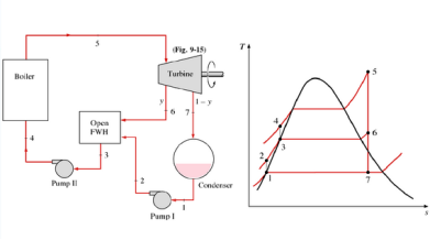
A7) An open (or direct-contact) feedwater heater is basically a mixing chamber, where the steam extracted from the turbine mixes with the feedwater exiting the pump. Ideally, the mixture leaves the heater as a saturated liquid at the heater pressure
Q8) Explain the closed feedwater heater
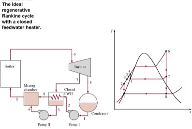
A8) Another type of feedwater heater frequently used in steam power plants is the closed feedwater heater, in which heat is transferred from the extracted steam to the feedwater without any mixing taking place. The two streams now can be at different pressures, since they do not mix
The closed feedwater heaters are more complex because of the internal tubing network, and thus they are more expensive. Heat transfer in closed feedwater heaters is less effective since the two streams are not allowed to be in direct contact. However, closed feedwater heaters do not require a separate pump for each heater since the extracted steam and the feedwater can be at different pressures. Open feedwater heaters are simple and inexpensive and have good heat transfer characteristics. For each heater, however, a pump is required to handle the feedwater.
Q9) Explain the Combined cycle power generation systems
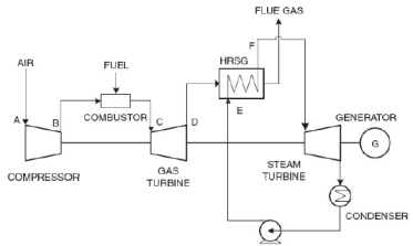
A9) A combined cycle gas turbine power plant is essentially an electrical power plant in which a gas turbine and a steam turbine are used in combination to achieve greater efficiency than would be possible independently. The gas turbine drives an electrical generator while the gas turbine exhaust is used to produce steam in a heat exchanger (called a Heat Recovery Steam Generator, HRSG) to supply a steam turbine whose output provides the means to generate more electricity. If the steam is used for heat (e.g., heating buildings) then the plant would be referred to as a cogeneration plant
Figure 1 is simple representation of a CCGT system. It demonstrates the fact that a CCGT system is two heat engines in series. The upper engine is the gas turbine. The gas turbine exhaust is the input to the lower engine (a steam turbine). The steam turbine exhausts heat via a steam condenser to the atmosphere.
The combine cycle efficiency (ηCC) can be derived by the equation 1 Langston.
ηCC = ηB + ηR - (ηB * ηR) ... (1)
Equation (1) states that the sum of the individual efficiencies minus the product of the individual efficiencies equals the combine cycle efficiency. This simple equation gives significant insight to why combine cycle systems are successful
. For example, suppose the gas turbines efficiency ηB is 40% (a reasonable value for a toady’s gas turbines) and that the steam turbine efficiency ηR is 30% (a reasonable value for Rankine Cycle steam turbine).
Utilizing equation (1) would lead to the following conclusion.
ηCC = 0.4 + 0.3 – (0.4 * 0.3)
ηCC = 0.58
ηCC = 58%
The combined cycle efficiency of 58% is much greater than either the gas turbine or the steam turbines efficiencies separately. The 58% value is slightly misleading in that system losses were ignored. Efficiency values in the 60% range have been recorded for CCGT systems in the past few years Chase.
Q10) Whate are the different fluid characteristics of Binary vapour cycles
A10) High Critical temperature and safe maximum pressure,
Low triple point temperature,
Condenser pressure which is not too low,
High enthalpy of vaporization,
Good heat transfer characteristics, and
Inert, easy availability at low cost.
Q11) Explain the Binary vapour cycles
A11) In the vapour power cycles most commonly used working fluid is water. But at high temperatures to get the high efficiency of vapour power cycle, some other working fluids are used. At high temperatures a few working fluids are used, which are mercury, sodium, potassium and sodium-potassium mixtures. Among these, only mercury has been used in practice
To increase the efficiency of Carnot cycle, with an increase in initial temperature or with the decrease in exit temperature of the fluid. At the normal pressure of 12 bar, the saturation temperature for water and mercury are 187o C, – 560o C, respectively. The highest temperature achieved in a power plant is about 550 – 600o C. Therefore, mercury is a better working fluid in the high temperature range, because its vaporization pressure is relatively low. Mercury vapour at high temperature with low pressure which avoid the difficulties connected with high pressure.
To get the high thermal efficiency of the power plant, by using two working fluids such as water and mercury, the binary vapour cycle has been developed. The power cycle, which is a combination of two cycles, one in the high temperature region and the other in the low temperature region, called the binary vapour cycle. In this cycle, the condenser of the high temperature cycle called the tapping cycle serves as the boiler of the low temperature cycle, termed the bottom cycle. Mercury water binary vapour cycle with
Cycle efficiency, 
Q12) A Carnol engine, working between 650 Kand 310 K, produces 150 Id of work. Find thermal efficiency and heat added during the process.
A12) T1 650K; T3 = 310K; W= 150kJ
Thermal efficiency
We know that thermal efficiency,
 =
=
Thermodynamic Air Cycles
Heat added during the process
We know that heat added during the process,

Q13) A Carnot engine operates between two reservoirs at temperatures T 1 and T1. The work output of the engine is 0.6 times the heat rejected. The difference in temperatures between the source and the sink is 200' C. Calculate the thermal efficiency, source temperature and the sink temperature
A13) W = 0.6 x Heat rejected = 0.6 Q; T - T = 200° C
Thermal efficiency
We know that the thermal efficiency


Source and sink temperatures
Let T1 = Source temperature, and
T3 =Sink temperature.
We know that thermal efficiency (ii),
0.375 =
=
T1= 200/0.375 = 533.3 K = 260,3° C Ans. T3= T1 -200= 260.3 —200 60.30 C Ans.