Unit - 4
Gas Power Cycles and Refrigeration cycles
Q1) What is the Otto Cycle?
A1) Otto cycle is a thermodynamic cycle upon which a spark ignition engine works. Spark Ignition (or SI) engine uses petrol (or Gasoline) as fuel. Otto cycle was invented by Nicolas Otto in 1876.
Spark ignition engine is a type of internal combustion engines.
Below are P-V and T-S Diagrams of the Otto Cycle.
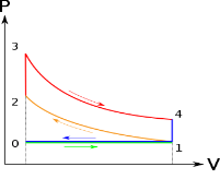
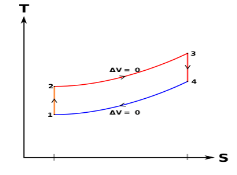
Otto Cycle is comprised of four processes (apart from the intake and exhaust process)
Process 1-2: This process comes after intake process. In case of SI engines, intake is a mixture of gasoline and air, also known as charge. In this process charge is compressed in isentropic manner. Temperature raised from T1 to T2 and volume decrease from V1 to V2.
Process 2-3: In this process the fuel gets blasted with the help of external spark (that is why the engine is known as spark ignition engine). This process is a constant volume heat addition process. Temperature raised from T2 to T3
.
Q2-3= CV(T3-T2)
Process 3-4: After the combustion process, the exhaust gases expend. This process is an isentropic expansion process. No heat is interchanged. The temperature falls from T3 to T4 and volume increase from V3 to V4.
Process 4-1: After the expansion process, exhaust valve opens. This results into sudden drop of pressure inside engine cylinder. This process is a constant volume heat rejection process.
Q4-1= CV(T4-T1)
Process 0-1 is the intake process and process 1-0 is the exhaust process.
Efficiency η = 1 – 1 / (r)y-1
Q2) Explain the Diesel Cycle
A2) Diesel cycle is a gas power cycle invented by Rudolph Diesel in the year 1897. It is widely used in diesel engines.
Diesel cycle is similar to Otto cycle except in the fact that it has one constant pressure process instead of a constant volume process (in Otto cycle).
Diesel cycle can be understood well if you refer its p-V and T-s diagrams.
P-V and T-s Diagrams of Diesel Cycle:
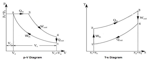
Figure: Diesel Cycles
Processes in Diesel Cycle:
Diesel cycle has four processes. They are:
Process 1-2: Isentropic Compression
In this process, the piston moves from Bottom Dead Centre (BDC) to Top Dead Centre (TDC) position. Air is compressed is entropically inside the cylinder. Pressure of air increases from p1 to p2, temperature increases from T1 to T2, and volume decreases from V1 to V2. Entropy remains constant (i.e., s1 = s2). Work is done on the system in this process (denoted by Win in the diagrams above).
Process 2-3: Constant Pressure Heat Addition
In this process, heat is added at constant pressure from an external heat source. Volume increases from V2 to V3, temperature increases from T2 to T3 and entropy increases from s2 to s3.
Heat added in process 2-3 is given by
Qin = mCP(T3 − T2) kJ ………… (i)
Where,
m→ Mass of air in kg
Cp → Specific heat at constant pressure in kJ/kg K
T2 → Temperature at point 2 in K
T3 → Temperature at point 3 in K
Process 3-4: Isentropic Expansion
Here the compressed and heated air is expanded isentropic ally inside the cylinder. The piston is forced from TDC to BDC in the cylinder. Pressure of air decreases from p3 to p4, temperature decreases from T3 to
decreases from p3 to p4, temperature decreases from T3 to T4, and volume increases from V3 to V4. Entropy remains constant (i.e., s3 = s4). Work is done by the system in this process (denoted by Wout in the p-V and T-s diagrams above).
Process 4-1: Constant Volume Heat Rejection
In this process, heat is rejected at constant volume (V4 = V1). Pressure decreases from P4 to P1, temperature decreases from T4 to T1 and entropy decreases from s4 to s1.
Heat rejected in process 4-1 is given by
Qout = mCv (T4 − T1) kJ ………… (ii)
Where,
m→ Mass of air in kg
Cv → Specific heat at constant volume in kJ/kgK
T2 → Temperature at point 2 in K
T3 → Temperature at point 3 in K
Q3) Explain the Dual Combustion cycle
A3) The combustion process in a spark ignition engine does not occur exactly at constant volume, nor does the combustion process in an actual compression ignition engine occur exactly at constant pressure, therefore another idealized cycle known as Dual cycle has been developed that more closely approximate the actual spark-ignition and compression-ignition engines. The p-v and T-s diagrams of Dual cycle are shown in Fig. 45.1. In this cycle, part of heat addition occurs at constant volume while the rest is at constant pressure. The dual cycle is also called mixed or limited pressure cycle.
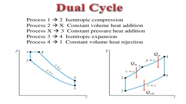
In a dual cycle, the system executing the cycle undergoes a series of five processes: two isentropic (reversible adiabatic) processes alternated with two isochoric process and one isobaric process:
Dual cycle – PV Diagram
Isentropic compression (compression stroke) – The gas is compressed adiabatically from state 1 to state 2, as the piston moves from intake valve closing point (1) to top dead centre. The surroundings do work on the gas, increasing its internal energy (temperature) and compressing it. On the other hand, the entropy remains unchanged. The changes in volumes and its ratio (V1 / V2) are known as the compression ratio. The compression ratio is smaller than the expansion ratio.
Isochoric compression (ignition phase) – In this phase (between state 2 and state 3) there is a constant-volume (the piston is at rest) heat transfer to the air from an external source while the piston is at rest at top dead center. This process is similar to the isochoric process in the Otto cycle. It is intended to represent the ignition of the fuel–air mixture injected into the chamber and the subsequent rapid burning. The pressure rises and the ratio (P3 / P2) is known as the “explosion ratio”.
Isobaric expansion (power stroke) – In this phase (between state 3 and state 4) there is a constant-pressure (idealized model) heat transfer to the air from an external source (combustion of the fuel) while the piston is moving toward the V4. During the constant pressure process, energy enters the system as heat Qadd, and a part of work is done by moving piston.
Isentropic expansion (power stroke) – The gas expands adiabatically from state 4 to state 5, as the piston moves from V3 to bottom dead center. The gas does work on the surroundings (piston) and loses an amount of internal energy equal to the work that leaves the system. Again, the entropy remains unchanged.
Isochoric decompression (exhaust stroke) – In this phase the cycle completes by a constant-volume process in which heat is rejected from the air while the piston is at bottom dead center. The working gas pressure drops instantaneously from point 5 to point 1. The exhaust valve opens at point 5. The exhaust stroke is directly after this decompression. As the piston moves from bottom dead center (point 1) to top dead center (point 0) with the exhaust valve opened, the gaseous mixture is vented to the atmosphere and the process starts anew.
During the Dual cycle, work is done on the gas by the piston between states 1 and 2 (isentropic compression). Work is done by the gas on the piston between stages 2 and 3 (isobaric heat addition) and between stages 2 and 3 (isentropic expansion). The difference between the work done by the gas and the work done on the gas is the network produced by the cycle and it corresponds to the area enclosed by the cycle curve. The work produced by the cycle times the rate of the cycle (cycles per second) is equal to the power produced by the Diesel engine.
Q4) Explain the Brayton Cycle
A4) It is theoretical cycle for gas turbines. It is also known as constant pressure cycle for a perfect gas. The basic component of Brayton Cycle is as shown in given figure-
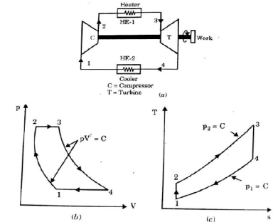
Figure: Brayton Cycle
The components are compressor, heat exchanger, turbine and cooler.
There occur two isentropic processes and two constant pressure processes. Compression and expansion of working fluid is done by isentropic process while addition and rejection of heat is done at constant pressure. In above figure, we can see the p-v and T-s diagram for the cycle.
Process 1-2: Air is being compressed isentropically by compressor between the pressure range p1 to p2.
Process 2-3: It is constant pressure heat pressure heat addition process. In this process temperature increases from T2 to T3 at constant pressure.
Process 3-4: The air is expanded isentropically pressure p2 to p1 and the temperature drops from T3 to T4.
Process 4-1: It is constant pressure heat rejection process as temperature reduces from T4 to T1.
Now, work done per cycle=Heat added/cycle-Heat rejected/cycle
Heat addition in process 2-3=mCp(T3-T2)
Heat rejected in process 4-1= mCp(T4-T1)
Work done per cycle=mCp(T3-T2)-MCp(T4-T1)


From process 1-2


Similarly, from process 3-4

Putting the values  and
and  in equation


The above equation shows that the efficiency of the ideal Brayton cycle increases with the pressure ratio.
Q5) Explain the Brayton cycle with regeneration
A5) Regeneration can be carried out by using the hot air exhausting from the turbine to heat up the compressor exit flow.
The thermal efficiency of the Brayton cycle increases as a part of the heat rejected is reused.
Regeneration decreases the heat input (thus fuel) requirements for the same net work output.

The highest temperature occurring within the regenerator is T4.
Air normally leaves the regenerator at a lower temperature, T5.
In the limiting (ideal) case, the air exits the regenerator at the inlet temperature of the exhaust gases T4.
The actual and maximum heat transfers are:
q regens, act = h5 - h2 and q regen, max = h5’- h2 = h4 - h2
The extent to which a regenerator approaches an ideal regenerator is called the effectiveness, ε and is defined as
ε = qregen, act / qregen, max = (h5 - h2)/ (h4 - h2)
Under the cold-air-standard assumptions, the thermal efficiency of an ideal Brayton cycle with regeneration is: • The thermal efficiency depends upon the temperature as well as the pressure ratio.

Q6) Explain the Brayton cycle with regeneration, reheating and intercooling effects
A6) Similarly the work output of a turbine can be increased by: multi-stage expansion with reheating.
As the number of stages of compression and expansion are increased, the process approaches an isothermal process.
A combination of intercooling and reheating can increase the net work output of a Brayton cycle significantly.

The net work output of a gas-turbine cycle improves as a result of intercooling and reheating.
However, intercooling and reheating decreases the thermal efficiency unless they are accompanied by regeneration.
This is because intercooling decreases the average temperature at which heat is added, and reheating increases the average temperature at which heat is rejected.

Q7) Explain the Ideal jet propulsion cycles
A7)


Ideal turbojet cycle (without afterburning) on a T-s diagram
a-1: Air from far upstream is brought to the air intake (diffuser) with some acceleration/deceleration
1-2: Air is decelerated as is passes through the diffuser
2-3: Air is compressed in a compressor (axial or centrifugal)
3-4 The air is heated using a combustion chamber/burner
4-5: The air is expanded in a turbine to obtain power to drive the compressor
5-6: The air may or may not be further heated in an afterburner by adding further fuel
6-7: The air is accelerated and exhausted through the nozzle
Afterburning: used when the aircraft needs a substantial increment in thrust. For e.g., to accelerate to and cruise at supersonic speeds. Since the air-fuel ratio in gas turbine engines are much greater than the stoichiometric values, there is sufficient amount of air available for combustion at the turbine exit. There are no rotating components like a turbine in the afterburner, the temperatures can be taken to much higher values than that at turbine entry
Q8) Explain the brief Refrigeration cycles: Reversed Carnot cycle
A8) Refrigeration Cycle
Heat flows in direction of decreasing temperature, i.e., from high-temperature to low temperature regions. The transfer of heat from a low-temperature to high-temperature requires a refrigerator and/or heat pump. Refrigerators and heat pumps are essentially the same device; they only differ in their objectives. The performance of refrigerators and heat pumps is expressed in terms of coefficient of performance (COP):


The Reversed Carnot Cycle Reversing the Carnot cycle does reverse the directions of heat and work interactions. A refrigerator or heat pump that operates on the reversed Carnot cycle is called a Carnot refrigerator or a Carnot heat pump.

The reversed Carnot cycle is the most efficient refrigeration cycle operating between two specified temperature levels. It sets the highest theoretical COP. The coefficient of performance for Carnot refrigerators and heat pumps are:


Q9) Explain the Reversed Brayton cycle
A9) Process 1-2: Reversible, adiabatic compression in a compressor
Process 2-3: Reversible, isobaric heat rejection in a heat exchanger
Process 3-4: Reversible, adiabatic expansion in a turbine
Process 4-1: Reversible, isobaric heat absorption in a heat exchanger

Process 1-2: Gas at low pressure is compressed isentropically from state 1 to state 2. Applying steady flow energy equation and neglecting changes in kinetic and potential energy, we can write:


And 
Where 
Process 2-3: Hot and high-pressure gas flows through a heat exchanger and rejects heat sensibly and isobarically to a heat sink. The enthalpy and temperature of the gas drop during the process due to heat exchange, no work transfer takes place and the entropy of the gas decreases. Again, applying steady flow energy equation and second T ds equation:


Process 3-4: High pressure gas from the heat exchanger flows through a turbine, undergoes isentropic expansion and delivers net work output. The temperature of the gas drops during the process from T 3 to T 4. From steady flow energy equation:


and 
where  pressure ratio
Process 4-1: Cold and low-pressure gas from turbine flows through the low temperature heat exchanger and extracts heat sensibly and isobarically from a heat source, providing a useful refrigeration effect. The enthalpy and temperature of the gas rise during the process due to heat exchange, no work transfer takes place and the entropy of the gas increases. Again, applying steady flow energy equation and second T ds equation:


From the above equations, it can be easily shown that

applying 1st law of thermodynamics to the entire cycle:

The COP of the reverse Brayton cycle is given by:

Using the relation between temperature and pressures, the COP can also be written as:

For fixed heat rejection temperature (T 3) and fixed refrigeration temperature (T1), the COP of reverse Brayton cycle is always lower than the COP of reverse Carnot cycle (Figure), that is

Q10) Explain the vapor compression cycle
A10)
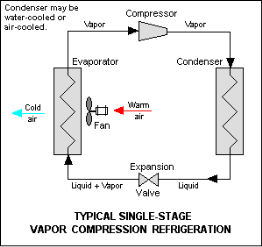
1. Compressor:
The vapour at low pressure and low temperature enters the compressor from the evaporator where it is compressed to high pressure and high temperature.
This high pressure and temperature vapour refrigerant are discharged into the condenser through the discharge valve.
2. Condenser:
The condenser or cooler consists of coils of pipe in which the high pressure and temperature vapour refrigerant are cooled and condensed.
The refrigerant while passing through the condenser gives up its latent heat to the surroundings condensing medium which is normally air or water.
3. Receiver:
The condensed liquid refrigerant from the condenser is stored in a vessel known as a receiver from where it is supplied to the evaporator through the expansion valve.
4. Expansion Valve:
It is also called a throttle valve. Its function is to allow the liquid refrigerant under high pressure and temperature to pass through it where it reduces its temperature and pressure.
5. Evaporator:
It also consists of coils of pipe in which liquid-vapour refrigerant at low pressure and temperature is evaporated and converted into vapour refrigerant at low pressure and temperature.
Q11) Explain the Working of Vapor Compression Refrigeration System
A11)

The working of Vapor Compression Refrigeration System can be completed under 4 processes and are as follows.
Compression Process:
The vapour at low temperature and low pressure enters the compressor where it is compressed is entropically and subsequently, its temperature and pressure considerably increase.
Condensation Process:
This vapour after leaving the compressor enters into the condenser, where it is condensed into high-pressure liquid and is collected in a receiver tank.
Expansion Process:
From the receiver tank, it passes through the expansion valve, where it is throttled down to low pressure and temperature.
Vaporization Process:
After finding its way through an expansion valve, it finally passes onto the evaporator, where it extracts heat from the surroundings or circulating fluid and vaporizes to lower pressure vapour.
If expansion takes place without throttling, temperature level drops to a very low level due to which it should undergo sensible heat and latent heat in order to reach the evaporation stage.
Note:
Q12) What is the C.O.P. of Vapor Compression Refrigeration System:
A12) The Coefficient of Performance (C.O.P) of a Simple Vapor Refrigeration Cycle is as follows.
C.O.P. = (heat extracted or refrigerating effect)/Work done.
C.O.P. = (h2-h1)/(h3-h2)
or
C.O.P. = (h2-h4)/(h3-h2).
Q13) Define the different Types of Vapor Compression Cycles
A13) The types of Vapor Compression Cycles which are important from the subject point of view are as follows.
Q14) What are the advantages of Vapour Compression Refrigeration System
A14)
Q15) What are the disadvantages Vapour Compression Refrigeration System
A15) The disadvantages of Vapor Compression Refrigeration system are as follows.
Q16) What are the application of Vapour Compression Refrigeration System
A16) The applications of Vapor Compression Refrigeration system are as follows.
Q17) Explain the vapor absorption cycle
A17)

Q18) Explain the Advantages of the vapor absorption cycle
A18)
Q19) Explain the Advantages of the vapor absorption cycle
A19)
Q20) What are the application of the vapor absorption cycle
A20)
Q21) In an Otto cycle, the temperature at the beginning and end of the isentropic compression are 316 K and 596 K respectively. Determine the air standard efficiency and the compression ratio. Take y = 1.4.
A21) Given: T =316K; T4 = 596K; y= 1.4
Let r = Compression ratio = V3 / V4
We know that for isentropic compression 3-4


Air standard efficiency
We know that air standard efficiency,

