Unit – 1
Kinematic fundamental
Q1) Explain the Classification of Mechanisms
A1) The mechanisms are of the following types:
On the basis of number of links
a. Simple mechanism: A mechanism which has four links.
b. Compound mechanism: A mechanism which has more than four links.
2. On the basis of number of pairs
a. Mechanism having three pairs.
b. Mechanism having 4 pairs.
c. Mechanism having more than 4 pairs.
3. On the basis of motion of particles
a. Planar mechanism: When all the links of the mechanism lie in the same plane.
b. Spatial mechanism: When the links of the mechanism lie in different planes.
Q2) Explain the Degrees of freedom.
A2) A free rigid body getting area will describe the subsequent freelance motions. change of location motions on any 3 reciprocally perpendicular axes x, y, and z, motility motions on these axes. Thus, a rigid body possesses six degrees of freedom. The association of a link with another imposes bound constraints on their relative motion. the number of restraints will ne'er be zero (the joint is disconnected) or six (joint becomes solid). Degrees of freedom of a try is outlined because of the variety of freelance relative motions, each change of location and motility, a try will have.
Degrees of freedom = 6 – no. of restraints. To find the number of degrees of freedom for a plane mechanism we've Associate in Nursing equation referred to as Grubler’s equation and is given by,
F = 3 (n – 1) – 2j1– j2
F = quality or a variety of degrees of freedom n = variety of links as well as the frame.
J1 = Joints with a single (one) degree of freedom. J2= Joints with 2 degrees of freedom. If F > 0, results in a mechanism with ‘F’ degrees of freedom. F = 0, leads to a statically determinate structure. F < 0, leads to a statically indeterminate structure. By taking the Associate in Nursing example of figure one.10, we can calculate the degrees of freedom simply. By the higher than given formula, F= 3(5-1)- 2*5= 2. So, there square measure two degrees of freedom within the mechanism shown in the figure.
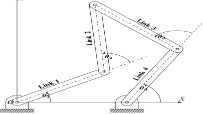
Figure. Five Bar Mechanism
Q3) Define the Type of Joints.
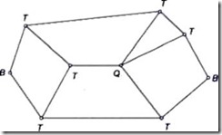
Binary Joint: If 2 links are joined at an equivalent connection; it's known as a binary joint. as an example.
Ternary Joint: If 3 links square measure joined at an affiliation, it's called a ternary joint. It's thought-about admire 2 binary joints since fixing of anybody link
constitutes 2 binary joints with every of the opposite 2 links.
In Fig. ternary links square measure mentioned as T.
Fig.
Quaternary Joint: If four links are joined at an association, it's referred to as a quaternary joint. It thought-about corresponding to 3 binary joints since the fixing of anybody link constitutes 3 binary joints. Figure 1.6 shows one quaternary joint.
In general, if ‘n’ variety of links are connected at a joint, it's corresponding to (n-1) binary joints.
Q4) What is the Kinematic Pair and its classifications?
A4) The 2 links or parts of a machine, once in grips with one another, square measure aforesaid to create a pair. If the relative motion between them is totally or with success forced the pair is thought of as kinematic pair.
Classification of pair is based on:
Sliding Pair: The 2 parts have a slippy motion relative to every alternative. Example: Piston and cylinder try rectangular rod is a rectangular line.
Turning Pair: Once the 2 parts square measure connected such the component revolves around the opposite component. Example: Shaft rotates within the bearing rotation of a crank during a slider-crank mechanism.
Rolling pair: once one component is absolved to roll on another component. Example: The belt and simple machine surfaces represent a rolling try.
Screw Pair: During this sort the contacting surface has threads. it's additionally known as a whorled try one component turns concerning another component by suggests that of thread solely. Example: A bolt and nut arrangement jack for lifting serious weights.
Spherical Pair: One component is within the type of sphere and turns concerning the fastened element; Example: ball and socket joint
2. In step with the sort of contact between the weather.
Lower Pair: If a try motion has surface contact between the weather. Example: Piston reciprocatory during a cylinder Shaft rotates during a bearing. (Contacting surfaces square measure similar)
Higher Pair: In higher try, there's a line or purpose contact between the weather.
Example: Cam and follower. (Contact surfaces square measure differently.)
3. In step with the sort of closure.
Self-Closed Pair: In this pair, two elements are held together mechanically; Example: All lower pair
Unclosed Pair/Force Closed Pair: The two elements are not held together mechanically; Example: Cam and followers.
Key Takeaways:
Kinematic pairs and their types, lower pair, higher pair, screw pair, turning pair and to know the exact similarity and difference between the two
Q5) Explain the Kinematic chain and mechanism
A5) When the kinematic pairs square measure coupled in such a way that the last link is joined to the primary link to transmit definite motion (i.e., utterly or with success affected motion) it is known as a kinematic chain. In alternative words, is also outlined as a mixture of kinematic pairs, joined in such the way that every link forms a neighborhood of 2 pairs and therefore the relative motion between the links or parts is totally or with success affected motion.
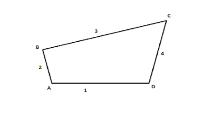
Figure. Kinematic Chain
When the kinematic pairs square measure coupled in such a way that the last link is joined to the primary link to transmit definite motion (i.e., utterly or with success affected motion) it's known as a kinematic chain. In alternative words, is also outlined as a mixture of kinematic pairs, joined in such the way that every link forms a neighborhood of 2 pairs and therefore the relative motion between the links or parts is totally or with success affected motion.
If every link is assumed to make 2 pairs with 2 adjacent links, then the relation between range the amount the quantity} of pairs (p) forming a kinematic chain and also the number of links (l) is also expressed within the style of associate degree equation:
l=2p-4
During a kinematic chain, every link forms a district of 2 pairs. Another relation between range the amount the quantity of links (l) and also the number of joints (j) that represent a kinematic chain is given by the expression:
j= 3/ (2l -2)
If within the example,
L.H.S > R.H.S, then it's thought-about as a barred chain
L.H.S = R.H.S, then it's thought-about mutually D.O.F
L.H.S < R.H.S, then it's thought-about as free Chain
Q6) Explain the Grubler’s criterion equation
A6) Grubler’s equation can be used to determine the mobility of planar mechanisms
Gruebler’s Equation
DOF = Mobility
L = Number of links
J = Number of revolute joints or prismatic joints
G = Number of grounded links


Q7) Explain the Inversion of mechanism
a) Kinematic inversion of 4 bar chain
b) Slider crank chain or singe slider crank chain
c) Double slider crank chain
Q8) Explain the Grashof criteria
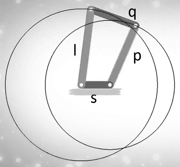
A8) Consider a four-bar mechanism as shown in the following figure:
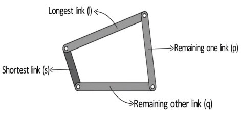
Figure. Grashof’s Law
s= shortest link
l= Longest link
p and q length of the other two links
By Grashof’s law, for at least one link to be capable of making a full revolution, the sum of the lengths of the shortest link and the largest link is less than or equal to the sum of the lengths of the other two links.
s + l ≤ p + q
The condition can be broken into two parts:
What happens if s+l > p+q?
For s+l>p+q, no link will be able to make a complete revolution, the mechanism so obtained is the triple rocker mechanism.

Figure. Triple Rocker Mechanism
In the triple rocker mechanism, one link is fixed while the other three oscillate.
Now, let us discuss the grashof condition. We broke the condition into two parts:
Case 1: The shortest link is adjacent to the first link.
The mechanism so obtained is the crank rocker mechanism.
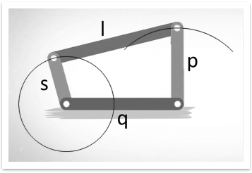
Figure. Crank Rocker Mechanism
In the crank rocker mechanism, the shortest link rotates fully while the other link pivoted to the fixed link oscillates.
Case 2: The shortest link is the fixed link.
The mechanism obtained in this case is known as a double crank mechanism.
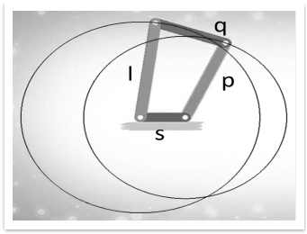
Figure. Double Crank Mechanism
In the double crank mechanism, both the links pivoted to the fixed link rotates fully.
Case 3: The shortest link is opposite to the fixed link
The mechanism obtained in this case is the double rocker mechanism.

Figure. Double Rocker Mechanism
In the double rocker mechanism, both the links pivoted to the fixed link oscillate. The shortest link, which is the coupler, makes a full revolution.
2. s+l = p+q
Case 1: The length of the link is distinct.
Example: ‘s’ is 1 unit, ‘l’ is 4 units, ‘p’ is 2 units and q is 3 units. In this case, s+l= p+q= 5 units. In this case, all the inversions obtained are the same as in the case ‘s+l=p+q’= 5 units. In this case, all the inversions obtained are the same as in the case ‘s+l < p+q’.
Case 2: The length of the two links is the same.
Example: p=s=1 unit and l= 4 units. Now for ‘s+l= p+q’, q=l= 4 units. So we have two pair of equal length.
In this way link can be joined in two ways :

Figure. Parallelogram and Deltoid linkage
All the inversions are either crank rocker or double crank for this case.
Q9) Explain the Single slider crank mechanism
A9) A single slider crank chain may be a modification of the fundamental four bar chain. It accommodates one slippery try and 3 turning pairs. it's typically found in a mutual external-combustion engine mechanism. this sort of mechanism converts motility into mutual motion and the other way around. during a single slider crank chain as shown in figure. the links one and a pair of, links a pair of and three, and links three and four type 3 turning pairs whereas link four and one forms a slippery pair. Link one corresponds to the frame of the engine, which is fastened. The link a pair of corresponds to the crank; link three corresponds to the rod and link corresponds to the crosshead. because the crank rotates, the crosshead reciprocates within the guides and so the piston reciprocates within the cylinder.
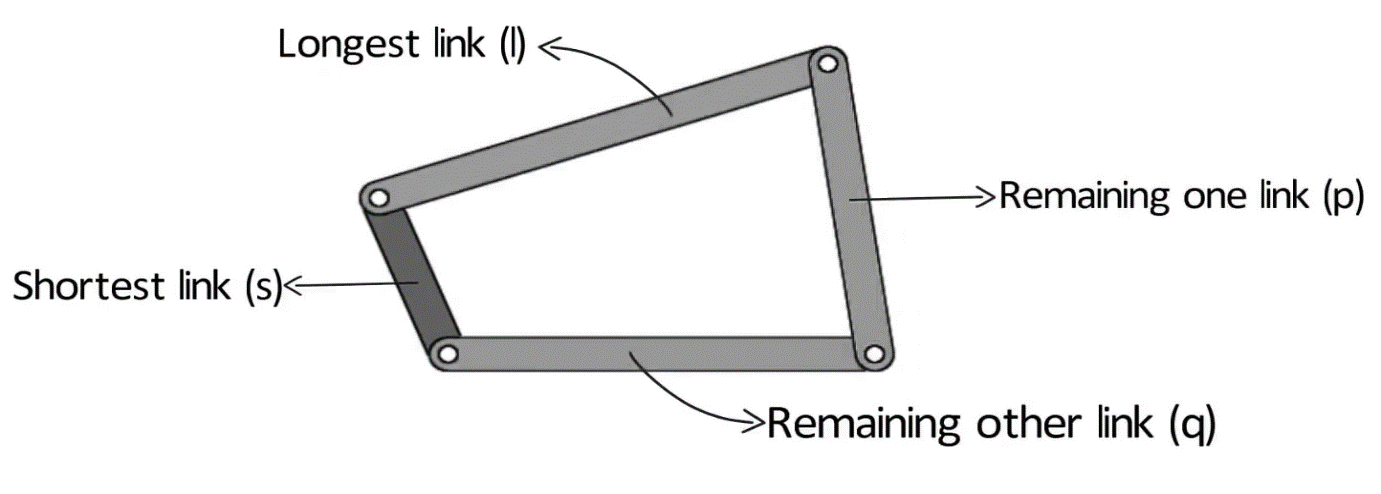
Figure. Single Slider Crank Chain
Inversions of Single Slider Crank Chain
We have seen within the previous article that one slider crank chain may be a four-link mechanism. we all know that by fixing, successively totally different links in an exceedingly kinematic chain, associate degree inversion is obtained and that we will obtain several mechanisms because of the links in an exceedingly kinematic chain. it's therefore obvious, that four bar inversions of one slider crank chain square measure doable
Q10) Explain the Double slider crank mechanism and their inversion
Inversions of Double Slider Crank Chain
It is an Associate in Nursing instrument used for drawing ellipses. This inversion is obtained by fixing the slotted plate (link 4) as shown in fig.1.28. The fastened plate or link four has 2 straight grooves cut in it, at right angles to every difference. Link one and link three square measure referred to as sliders and type slippery pairs with link four. The link AB (link 2) may be a bar that forms turning combine with links one and three. When the links one and three slides on their grooves, Associate in Nursing purpose on the link a pair of like P traces out an oval on the surface of link four, as shown as fig.1.28. a bit of thought can show that AP and BP square measure the semi-major and semi-axis of the oval severally. this could be proved as follows:

Figure. Elliptical Trammels
x= PQ = AP cos  and y= PR = BP sin
 = cos
= cos ;
;  = sin
= sin 
Squaring and adding both sides,
 +
+  =1
=1
Hence traced by point P is an ellipse.
2. Scotch Yoke Mechanism
This mechanism is employed for changing movement into reciprocatory motion. The inversion is obtained by fixing either link one or link three. In fig1.29 link one is mounted whereas link two (which corresponds to the crank) rotates regarding B as center, the link four (which corresponds to a frame) reciprocates. The mounted link guides the frame.

Figure. Scotch Yoke Mechanism
3. Oldham’s Coupling
An Oldham’s coupling is employed for connecting 2 parallel shafts whose axes are at a little distance apart. The shafts are coupled in such a way that if one shaft rotates, the opposite shaft conjointly rotates at an identical speed. The inversion is obtained by fixing link two as shown in fig.1.29 (a). The shafts to be connected have 2 flanges (link one and link 3) stiffly mounted at either end by formation. Link one and link three types turning combine with link two. These flanges have diametrical slots cut in their inner faces as shown in fig.1.30(c). The tongues on link four closely match into {the 2} slots within the two flanges (link one and link 3). Link four will slide or reciprocate within the slots within the flanges. When the driving shaft A is turned, projection C (link 1) causes the intermediate piece (link 4) to rotate at an identical angle through that projection is turned and it rotates the projection D speed at each instant.

(a) (b) (c)
Figure. Oldham’s Coupling
Q11) Explain the Transmission angle and toggle position
A11) As a mechanism moves over a range of motion its geometry changes. If we are using a mechanism to transmit torque, or force then we must consider the ratio between the input and output force in various positions.
Transmission angle is the angle between the coupling member and the output member in a mechanism. As this angle approaches ±90°, the mechanical advantage of the mechanism typically increases.
Toggle positions occur when the input crank has near infinite mechanical advantage. Note: this also applies that the follower has no mechanical advantage on the crank.
Q12) What is the Mechanical advantage?
A12) The mechanical advantage of a mechanism is the ratio of output force or torque to the input force or torque at any instant Thus for the linkage of fig if friction and inertia force are ignored and the input torque T2 is applied to link 2 to drive the output link 4 with resisting torque t4 drive the output 4 with resisting torque T4 then
Power input = power output
T4 – T4
– T4 
 =
=
Thus, it is reciprocal of the velocity ratio.in case of crank rocker mechanisms the velocity w4 of the output link DC become zero at the extreme case of crank rocker mechanisms the velocity  4 if the output link AB is in with couple BC and the angle
  between them is either zero or 180
 it makes the mechanical advantage to be infinite at such position.
