Unit - 1
Geometry of cutting tools in ASA and ORS
Q1) Explain tool Signature in ASA System?
A1)
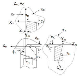
Machine longitudinal plane, Machine transverse plane, and Reference plane are three mutually perpendicular planes used by the American Standards Association (ASA) for reference purposes. Two rake angles, two clearance angles, two cutting edge angles, and the nose radius of a single point cutting tool make up the ASA tool signature. The sequence of writing tool signatures in the ASA system is shown here, along with the names of various angles. It is important to remember that though various people may use various symbols, the sequence must be followed. Below is an example of a typical scenario.
ASA system of turning tool designation | ||||||
 |  |  |  |  |  |  |
 | 5  |  | 6  | 10  | 30  | 1/12 |
Back rack angle | 0  | |||||
Orthogonal rake angle (  | 5  | |||||
Back clearance angle |  | |||||
Side clearance angle | 6  | |||||
End cutting edge angle | 10  | |||||
Approach angle | 30  | |||||
Nose radius | 1/12 inch | |||||
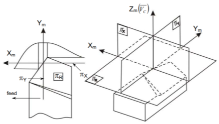
The ASA system's reference planes and axes
The following are the reference planes and coordinates used in the ASA system for tool geometry:
 and
and 
Where,
ΠR = Reference plane; plane perpendicular to the velocity vector (shown in Fig.)
ΠX = Machine longitudinal plane; plane taken in the direction of anticipated longitudinal feed and perpendicular to _R.
ΠY = [This plane is taken in the direction of presumed cross feed] Machine Transverse plane; plane perpendicular to both _R and _X
The longitudinal feed, cross feed, and cutting velocity (vector) axes are Xm, Ym, and Zm, respectively. Fig shows the key geometrical features and angles of single point tools in ASA systems, as well as their definitions.
Q2) Explain tool signature in ORS system?
A2)
For reference, the Orthogonal Rake System (ORS) uses three mutually perpendicular planes: Cutting plane, Orthogonal plane, and Reference plane. Tool signature in the ORS system consists of two rake angles, two clearance angles, two cutting edge angles, and the nose radius of a single point cutting tool, similar to the ASA system. Note that the ASA method measures nose radius in inches, but the ORS method measures it in millimetres. The sequence of writing tool signatures in the ORS system is shown here, along with the names of various angles. The sequence, as is customary, cannot be changed, however alternate notation can be used. Below is an example of a typical scenario.
OSR system of turning tool designation | ||||||
|  |  |  |  |  |  |
 | -7  | 10  | 8  | 15  | 60  | 0.8  |
Inclination angle () | 0  | |||||
Orthogonal rake angle (  | -7  | |||||
Orthogonal clearance angle (  | 10  | |||||
Auxiliary Orthogonal clearance angle  | 8  | |||||
Auxiliary cutting edge angle  | 15  | |||||
Principal cutting edge angle (  | 60  | |||||
Nose radius (r) | 0.8mm | |||||
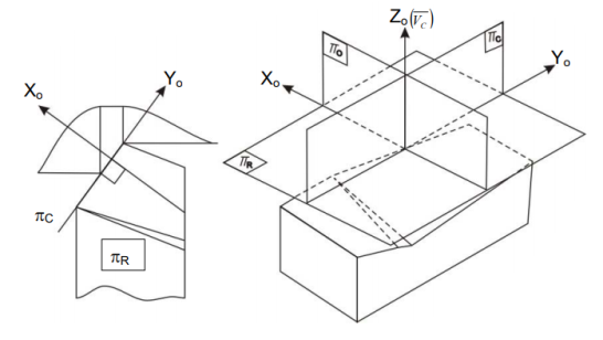
ORS planes and axes of reference
Q3) State the effect of cutting parameters on forces.
A3)
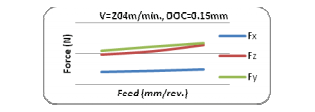
Understanding the effect of cutting parameters on tool forces and surface roughness is critical for fine-tuning the process for the most efficient cutting within the defined range of cutting parameters. The response surface graphs for various force components and surface roughness created were plotted using the regression equations mentioned in the previous section. As shown in figures a, b, and c, the axial forces (Fx) increased as the depth of cut increased, but it had no effect on cutting speed or feed.
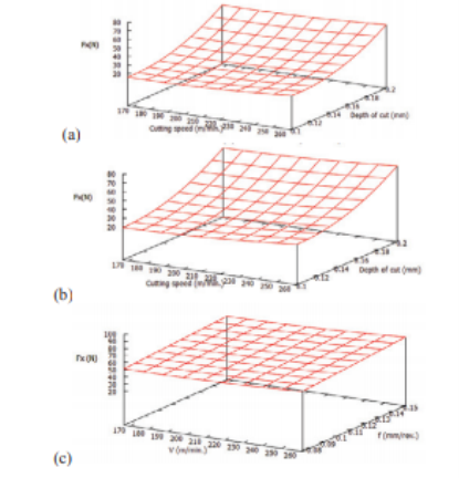
The radial force (Fy) rose as the cut depth grew. At lower feeds, it grew as the speed increased (fig. a), but at higher feeds and deeper cuts, the radial force first decreased, then increased a little. In fig. c, the tendency is considerably more obvious. This could be because the workpiece becomes sufficiently thermally softened at high depths of cut and feed that additional increases in cutting speed have no influence on the process. As seen in figures, this might happen within a particular critical range of cutting speed, which in this case is between 170 and 220 m/min.
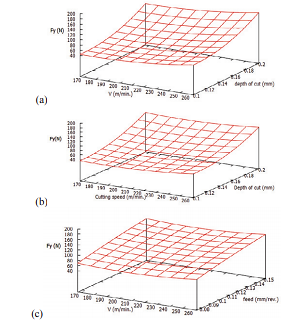
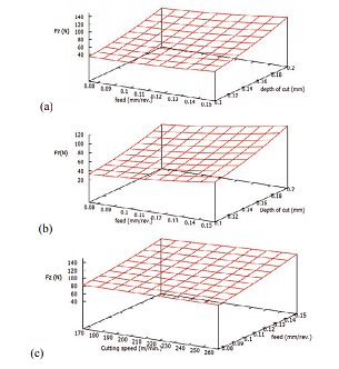
Cutting force component (Fz) rose as feed and cut depth rose (fig a and b). However, in the defined range of machining parameters, it showed indifference to cutting speed (fig c). This could be because the work piece material becomes thermally softened and thus more machinable at high feed and speed.
Q4) State the Effect of cutting parameters on surface roughness.
A4)
The fluctuation in surface roughness with cutting settings is shown in Figures a, b, and c. For majority of the feed values in the range, the surface roughness increased as the depth of cut rose. However, with low depth cuts, it first reduced and then grew as feed increased. While, for high depth of cut in the selected range, the surface roughness decreased with increase in feed (fig. a and b).
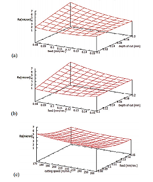
Surface roughness in the turning direction decreased with increased cutting speed, but the roughness value decreased with increased feed, as shown in Fig. c. The cause for this could be that the material was ploughed at a low feed rate. Because of the low feed, the uncut chip thickness would be relatively thin, resulting in ploughing instead of cutting at low feeds, resulting in increased surface roughness. As the feed level rises, the ploughing effect decreases, resulting in a better surface.
Q5) What are the condition for efficient cutting?
A5)
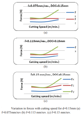
Figure show the examples where the cutting force values were virtually identical to the radial force. These were the most efficient cuts since they demonstrated that cutting used more power than holding the tool in a transverse direction. Figures a, b, and c show that low and moderate cutting speeds in the selected range, as well as a moderate depth of cut, may be the most efficient.
Figure also indicates that by keeping speed and depth of cut in the selected range at moderate levels, the most efficient cut may be attained for practically all feeds. It may be determined that lower to moderate speeds and medium depths of cut of the given parameter range should be employed to accomplish energy efficient machining.
Q6) State Chip Formation.
A6)
The goal of every milling and turning operation is to eliminate material in order to attain the completed part's specified dimensions.
Although milling and turning appear to use drastically different procedures, the fundamental principle of material removal by chip production is the same in both.
The example of a planning machine is possibly the easiest to imagine to demonstrate the principle of chip creation. Planning will not be detailed in depth; suffice it to state that the tool and workpiece move along a linear path, and the tool generates chips in a manner that is basically similar to milling and turning
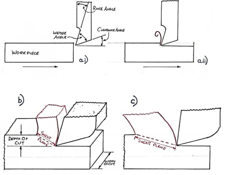
A planer is shown in Fig in a side view, relative to feed direction, before the tool and work piece are engaged. The rake and clearance angles are two of the most significant variables to consider in chip production; note that the wedge angle formed is a direct link between these two angles; that is, the bigger the total of clearance and rake angle, the smaller the wedge angle.
The clearance angle ensures that just the tool's cutting edge makes contact with the work piece, and that the tool's rear, or heel, does not rub against the finished surface, deteriorating the finish and requiring more power.
The lower the wedge angle, the weaker and less able to disperse heat is the tip of the tool, as shown in. As a result, the ‘perfect' rake and clearance angles for a given material are frequently a compromise between outright cutting ability and acceptable strength.
Different sorts of chips can form under various cutting conditions, such as varied depths of cut, work piece material, rake angles, cutting speed, and machine rigidity. Continuous and discontinuous chips are the two primary types of chips.
Q7) What is merchant theory?
A7)
The notion of minimum energy underpins this hypothesis. According to this theory, the angle will take on a value that will result in the least amount of cutting labour.
Because the work done is only dependent on the cutting force component Fp, the angle should be set so that Fp is at a minimum for the provided.
From the diagram of a merchant's circle,


Where Z= mean shear stress
B= width of the chip
t= uncut chip thickness.
Shear will occur when the shear strength on the plane described by angle is totally equal to the shear strength ′ of the materials.
For a simple analytic it is assumed to be constant.

For minimum Fp


Which gives a minimum value, or,

Q8) What is Chip Breaker?
A8)
• A continuous type chip from a lengthy cut is usually a pain to remove from the swarf tray because it fouls the tools, clutters the machine, and causes a mess in the workplace.
•Chip breakers are used to reduce the swarf into little bits as they are generated, making it easier to handle and preventing it from becoming a workplace danger.
• The chip breaker performs better because the metal has previously been working hardened.
• Chip breakers come in a variety of shapes and sizes, but they all have a step or groove ground into the tool's leading edge or a piece of cutting tool material fastened on top.
• The following are the most popular methods of breaking the chips in everyday shop practise:
o By clamping a piece of sheet metal over the coil's route.
o With a stepped type breaker, a step is ground into the tool's face along the cutting edge.
o Using a groove type breaker, which grinds a little groove below the cutting edge.
o With a clamp breaker, a thin carbide plate or clamp is brazed or fastened onto the tool's face.

Q9) What are the steps to draw merchant’s circle diagram?
A9)
Consider the state of an orthogonal cutting process with the specified feed, tool geometry, and cut depth. We only have the values of two forces (Fx and Fz) that are measured with a dynamometer now. We'll derive the other force relations quickly and easily using the merchant's circle diagram and associated equations.
• Calculate the value of Fx, the thrust force.
• Draw the chip and tool on the orthogonal plane, knowing the tool's rake angle.
• Draw the horizontal component of force Fz and the vertical component of force Fx.
• Fx and Fz's resultant force F is drawn for the forces. A formula is used to calculate the value of the resulting force FF.

• Draw a circle around the midpoint of the resultant force F.
• Extend the tool's rake surface by extending a line along with it and mark it as friction force P.
• Create a normal force N that is perpendicular to the friction force P. A formula is used to calculate the friction coefficient.
μ=PN
• Using a shear angle, draw the shear plane.
• The value of the shear angle is calculated using a formula that has already been developed.

Draw Fs and Fn as intercepts.
Q10) State the properties for Coating – CVD.
A10)
Chemical Vapor Deposition (CVD) is an acronym for Chemical Vapor Deposition. Chemical reactions at temperatures ranging from 700 to 1050°C produce the CVD coating.
CVD coatings provide great adherence to cemented carbide and have a high wear resistance.
The single layer titanium carbide coating was the first CVD coated cemented carbide (TiC). Later on, alumina (Al2O3) and titanium nitride (TiN) coatings were developed. Modern titanium carbonitride coatings (MT-Ti (C, N) or MT-TiCN, also known as MT-CVD) were created more recently to increase grade qualities by keeping the cemented carbide interface intact.
MT-Ti (C, N), Al2O3, and TiN are all used in modern CVD coatings. Through microstructural optimizations and post-treatments, the coating qualities for adhesion, toughness, and wear have been constantly improved.
MT-Ti (C, N) - Its hardness makes it resistant to abrasive wear, resulting in less flank wear.
CVD-Al2O3 is chemically inert and has a low thermal conductivity, making it crater-resistant. It also serves as a thermal barrier to help prevent plastic deformation.
CVD-TiN - Increases wear resistance and can be used to monitor wear.
Post-treatments improve edge hardness and prevent smearing in interrupted cuts.
Q11) State the properties for Coating – PVD
A11)
PVD coatings (Physical Vapor Deposition) are created at low temperatures (400-600°C). The method entails the evaporation of a metal, which then combines with nitrogen to generate a hard nitride coating on the cutting tool surface.
Due to its hardness, PVD coatings increase wear resistance to a grade. Edge toughness and comb crack resistance are also improved by their compressive stresses.
The key components of PVD coatings are listed below. These elements are combined in sequenced layers and/or lamellar coatings in modern coatings. Lamellar coatings have many thin layers in the nanoscale range, increasing the coating's hardness.
PVD-TiN - The first PVD coating was titanium nitride. It has a golden colour and all-around characteristics.
PVD-Ti (C, N) - Titanium carbonitride is tougher than TiN and adds resistance to flank wear.
PVD- (Ti, Al) N - Titanium aluminium nitride has a high hardness and oxidation resistance, resulting in improved overall wear resistance.
PVD-oxide is employed because of its chemical inertness and increased crater resistance.
Q12) What is ceramic cutting tool material?
A12)
At high cutting speeds, all ceramic cutting tools have good wear resistance.
A number of ceramic grades are offered for various uses.
Oxide ceramics are made of aluminium oxide (Al2O3) with zirconia (ZrO2) added for crack resistance. This results in a material that is chemically very stable but not thermally shock resistant.
(1) Cubic carbides or carbonitrides (TiC, Ti (C, N)) are used to particle-reinforce mixed ceramics. Toughness and thermal conductivity are improved as a result.
(2) Silicon carbide whiskers (SiCw) are used to greatly increase toughness and permit the use of coolant in whisker-reinforced ceramics. For machining Ni-based alloys, whisker-reinforced ceramics are excellent.
(3) Another type of ceramic material is silicon nitride ceramics (Si3N4). Their elongated crystals form a self-reinforced, high-toughness material. Silicon nitride grades function well in grey cast iron, but their chemical stability prevents them from being used in other materials.
Sialon (SiAlON) grades combine the strength and chemical stability of a self-reinforced silicon nitride network. Sialon grades are good for machining super alloys that are heat resistant (HRSA).

Q13) State the Tool Wear Mechanism – Abrasion, Adhesion, Diffusion, Fatigue and Oxidation Wear.
A13)
It is necessary to understand the limitations and applications of tool material in order to comprehend the many wear mechanisms that a cutting tool is subjected to.
Abrasion wear
This is the most typical wear mechanism. When a hard particle on a chip travel over the cutting tool face, abrasion occurs. In steel alloys, it is caused by oxides, nitrides and other non-metallic inclusion present in the workpiece. This hard inclusion having sharp edges comes in contact with a cutting tool and removes material from the tool surface by abrasion action. This wear pattern is more consistent, resulting in a longer tool life.
Adhesion wear or attrition wear
Chip material ripped off the small piece from the tool, causing adhesion wear. The tool-chip interface generates a metallic bond in the form of spot welds at high temperature and pressure at the cutting edge. A spot weld causes an erratic flow of chips across the tool face, resulting in built-up edges. The fracture of this minor weld joint, as well as some tool material, is caused by the chip sliding over the built-up, a phenomenon called as adhesion. Cutting fluids that form a protective coating on the contact surface can help prevent adhesive wear.
Diffusion wear
Diffusion wear occurs when atoms in a crystal lattice shift from an area of high concentration to a region of low concentration (Ficks law). The surface structure of a cutting tool is weakened by diffusion, which leads to tool failure. Localized temperature at the tool-chip interface provides a suitable environment for diffusion.
Temperature affects the amount of diffusion.
The solubility of tool material in work material, as well as the binding affinity of tool and chip materials.
Contact time between the tool and the chip.
Fatigue wear
When two surfaces glide in touch with each other under high pressure, it occurs at the microscopic level. On one rough surface, a hill interlock with those on another. As it slips over another slope, it produces cyclic stress. A surface that is exposed to fatigue wear due to frequent loading and unloading. When other wear rates are really low, it only comes to measure. Surface cracks are caused by fatigue wear, which eventually merge and lead to surface crumble. Another cause of fatigue wear is cyclic thermal stress.
Oxidation wear (corrosive wear)
Oxidation develops a layer of oxides on the tool surface as a result of a chemical interaction between the tool surface and oxygen at high temperatures. When this layer is abrasion-destroyed during the cutting process, a new layer form. As this removal and development of the corrosive layer is repeated, tool wear occurs.
Edge chipping (premature wear)
Breaking away of small chips from cutting edge of the tool due to interrupted cutting and sudden shock. When cutting with a variable depth of cut, this happens.
Q14) What are Essential properties of cutting fluids
A14)
The cutting fluid should have the following attributes in order to fulfil its functional needs without hurting the Machine – Fixture – Tool – Work (M-F-T-W) system or the operators:
- For cooling:
- High specific heat, thermal conductivity and film coefficient for heat transfer
- Spreading and wetting ability
- For lubrication:
- High lubricity without gumming and foaming
- Wetting and spreading
- High film boiling point
- Friction reduction at extreme pressure (EP) and temperature
- Chemical stability, non-corrosive to M-F-T-W system materials
- Less volatile and high flash point
- High resistance to bacterial growth
- Odourless and preferably colourless
- Non-toxic in both liquid and gaseous states
- Readily available and inexpensive cost.
Q15) What are Factors Affecting Machinability?
A15)
Factors affecting the machinability of metals are as follows:
i. The type of work-piece, i.e., the material;
Ii. The type of tool material;
Iii. Tool size and shape;
Iv. Machining operation type;
v. Cut size, form, and speed;
Vi. The type and grade of the machine that was employed;
Vii. Lubricant quality during machining operations;
Viii. Friction coefficient between the chip and the tool;
Ix. Workpiece material shearing strength
The tool must first penetrate the surface to remove metal through machining. The chip generated by the tool should easily break once it has penetrated the surface. Providing a built-in breaker is the best way to break the chip. It is a common misconception that soft metals are simple to machine.
Toughness is sometimes a consequence of softness, and as a result, the chips generated are difficult to separate. A totally spheroidized structure in steel is said to be the easiest to machine.
Machinability is the ease with which a particular material can be machined, and it is influenced by machine factors such as cutting speed, feed, and depth of cut, tool form, tool material, cutting fluid, machine tool stiffness, shape and size of work, and nature of tool contact with work.
The qualities of the work material, such as hardness, tensile characteristics, chemical composition, microstructure, degree of cold work, and strain hardenability, influence the ease of machining for a particular set of machine parameters.
Common machining criteria include tool life between resharpening (stated in many ways), cutting forces encountered and power consumption, surface smoothness, and chip disposal ease, among others.
Q16) What is machinability index of metal?
A16)
In various cutting processes, the machinability index is used to compare the machinability of different materials. It is a method of determining the relative machinability of various materials. The machinability rating may differ depending on the cutting operation, such as turning, milling, or shaping. Except for the speed, elements such as tool material, tool geometry, tool life, and other cutting circumstances are fixed when calculating the machinability index. Then, for a certain tool life, determine the speed at which the tool cuts the material. The material is then compared to a standard material. The machinability of standard steel is arbitrarily set to 100% in this example. Low metal removal rate and thus poor machinability are indicated by the slower speed.
Machinability index, 
Vi = Cutting speed of metal investigated for 20-minute tool life
Vs = Cutting speed of standard steel for 20-minute tool life
Q17) State Taylor formula for tool life?
A17)
The various ways of describing the tool's life cycle
The tool life can be expressed in a variety of ways, including
The most widely used tool life unit is the time unit.
The amount of material removed by a tool over the course of its life.
The number of workpieces that a tool has machined.
The predicted life of several tool materials is provided below. Tool life is most usually represented in minutes.
120-minute cast tool steel
60 to 120 minutes using a high-speed steel tool
Tool made of cemented carbide - 420 to 480 minutes
The level of machining parameters, such as cutting velocity (V C), feed (S 0), and depth of cut (D 0), determine the wear and hence tool life of any tool for any work material (t). Cutting velocity has an impact on the maximum and minimum cut depths.
In Fig., the typical pattern of cutting tool wear (mostly VB), the basis of determining tool life, and its relationship to cutting velocity are graphically depicted.
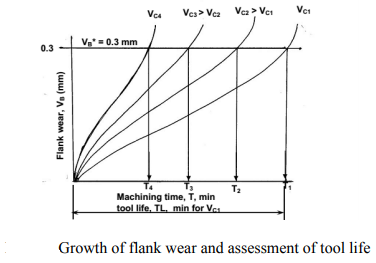
When seen in Fig., tool life reduces as cutting velocity increases, while other variables remain unchanged.
If the tool lives, ,
, ,
,  ,
, etc are plotted against the corresponding cutting velocities,
  ,
,  ,
,  ,
,  etc as shown in Fig, a smooth curve like a rectangular hyperbola is found to appear. When F. W. Taylor plotted the same figure taking both V and T in log-scale, a more distinct linear relationship appeared as schematically shown in Fig.
With the slope, n and intercept, c, Taylor derived the simple equation as

Taylor's tool life exponent is denoted by the letter n. The values of both ‘n' and ‘c' are largely determined by the materials used in tooling and the cutting environment (cutting fluid application). C's value is likewise influenced by undertaken's limiting value (i.e., 0.3 mm, 0.4 mm, 0.6 mm etc.).
Q18) What is Drilling dynamometer?
A18)
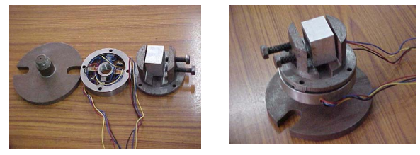
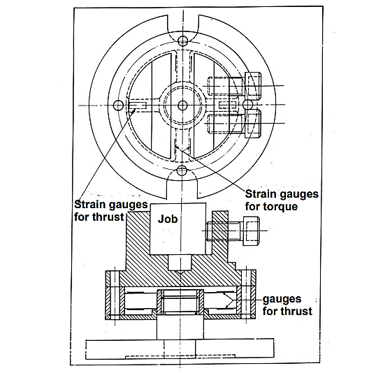
Figures demonstrate the schematic and pictorial construction of a strain gauge type 2 – D drilling dynamometer for measuring torque and thrust force. Four strain gauges are mounted on the upper and lower surfaces of the two opposite ribs for Px – channel and four on the side surfaces of the other two ribs for the torque channel. The dynamometer must be calibrated before use so that the real values of T and Px may be determined from the voltage values or readings taken in SMB or PC.
Q19) What is actual cutting time (Tc) also state the mathematical equation?
A19)
Cutting time, as the name implies, is the time spent actually removing material, i.e., from the start of chip creation until the end of uninterrupted machining. The pause duration will not be included in this time factor whether there is a deliberate or inadvertent delay in cutting. As a result of the increased cutting speed and feed rate, the actual cutting time will be reduced as the material removal rate (MRR) increases. As a result, if the speed or feed is increased, the cost associated with cutting time will drop. The diagram on the right shows how the cost of actual cutting time varies depending on the speed or feed used during machining.
Mathematical expression of actual cutting time
If, Lc is the total length of cut (mm), N is the spindle speed (rpm) and s is the feed rate (mm/rev), then estimated uninterrupted cutting or machining time can be expressed as:

The spindle speed (N) and cutting velocity (Vc) are interchangeable in most circumstances where either the workpiece or the cutting tool is rotating. Cutting velocity, on the other hand, is influenced by the job/cutter diameter (D). Cutting velocity can be stated as follows in terms of speed and task or cutter diameter (whichever is spinning). You can learn more about this conversion by reading Cutting speed and cutting velocity in machining.

In case of turning or milling, actual cutting time can be expressed as:


Q20) With a feed rate of 0.050ipr, a turning cut was achieved in a magnesium workpiece. The cutting speed was 300 feet per minute, and the cutting force was 200 pounds. The lathe is 95% efficient and has a 0.1 horsepower idle horsepower. Estimate the horsepower necessary for the cut using all of the information provided.
A20)

Q21) The uncut chip thickness in orthogonal machining with a tool with a 9° orthogonal rake angle is 0.2mm. The thickness of the chip varies between 0.25mm and 0.4mm. In this situation, find the ratio of the highest shear angle to the minimum shear angle.
A21)
Machining is a subtractive manufacturing process in which material is gradually removed from the workpiece by shearing while the cutting tool exerts compressive stress. Shear plane refers to the supposed plane along which shearing occurs. Shear angle refers to the angle of this shear plane with respect to the cutting velocity vector. As shown below, the orthogonal shear angle ( ) can be defined in terms of the orthogonal rake angle (
 ) and the chip reduction coefficient (
 ).
).

 = Orthogonal shear angle
 = Orthogonal rake angle
a1 = Uncut chip thickness
a2 = Chip thickness > a1
Chip reduction coefficient  > 1
> 1
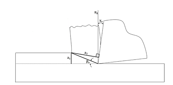
When a specific tool is selected for machining, the rake angle of the cutting tool falls under tool geometry and can be classified as an independent variable. However, the chip reduction coefficient ( ) is a variable that is influenced by a number of factors. Chip reduction coefficient is defined as the ratio of chip thickness (a2) to uncut chip thickness (a1) (a1). Because of lamellar shearing and straining in traditional macro-scale cutting, chip thickness is always greater than uncut chip thickness (i.e., a2 > a1). Mathematically,
ζ = (a2 / a1) > 1
In this situation, the uncut chip thickness (a1) is 0.2mm, and the orthogonal rake angle ( ) is +9 degrees. As a result,
  is inversely proportional to
  from the generic expression of shear angle (
 ) given at the beginning. In addition,
  is inversely proportional to a2.

