Unit – 2
Conventional machining process and machine tools
Q1) What is Turning in Conventional Machining?
A1)
We have a variety of traditional turning lathes. The largest one can turn workpieces up to 400 mm in diameter and 2000 mm in length, and/or up to 800 mm in diameter and 350 mm in length. This machine was manufactured in 2013, and it features a 4-clamping jaw, various steady rests, and digital measuring sticks.
Turning is a machining method in which the workpiece is spun as cutting tools travel across it on a lathe. To make cuts with exact depth and width, the cutting tools move along two axes of motion. Traditional manual lathes and automated computer numerical controlled (CNC) lathes are the two types of lathes available.
The turning technique can be applied to the outside or inside of a material. When done on the inside, it's referred to as "Boring”—the most frequent way for producing tubular components (which can be horizontal or vertical depending on the spindle orientation). The term "turning process" refers to another aspect of the process "During the early and last stages of the turning process, the cutting tool goes across the end of the workpiece, a process known as "facing." Only a lathe with a fitting cross-slide can be used for facing. It is used to create a perpendicular to the rotational axis datum on the face of a casting or stock shape.
Turret lathes, engine lathes, and special purpose lathes are the three types of lathes that are commonly used. Engine lathes are the most frequent type used by hobbyists and general machinists. Turret lathes and special purpose lathes are more typically employed for pieces that must be manufactured repeatedly. A tool holder on a turret lathe allows the machine to complete multiple cutting operations in a row without interruption from the operator. Disc and drum lathes, for example, are used in an automotive garage to reface the surfaces of brake components.
CNC mill-turning centres combine typical lathe head and tail stocks with additional spindle axes to enable efficient machining of items with rotational symmetry (such as pump impellers) and the milling cutter's ability to manufacture complicated features. 5-axis machining allows complex curves to be generated by rotating the workpiece around an arc while the milling cutter goes along a different path.
Q2) What is Drilling?
A2)
Boreholes and thread cutting can be made in any type of workpiece using various drilling machines.
Drilling uses drill bits to generate cylindrical holes in solid materials; it is one of the most essential machining techniques since the holes formed are typically used to aid with assembly. Drill presses are frequently employed, however lathes can also be employed. Drilling is a preparatory step in most manufacturing operations for producing finished holes, which are then tapped, reamed, bored, etc. to generate threaded holes or bring hole dimensions within acceptable tolerances. Due to the bit's flexibility and tendency to seek the route of least resistance, drill bits will frequently cut holes that are larger than their nominal size and holes that are not always straight or round. As a result, drilling is frequently specified undersize and followed by a machining process to bring the hole to its final size.
Two helical grooves run up the shaft of the drill bits that were employed. As the bit penetrates into the material, the "fluting" carries the chips, or swarf, out of the hole. There is a recommended drill speed and feed for each type of material.
Boring is used to refine the dimensions and accuracy of a drilled hole, despite the fact that drilling and boring are frequently confused. Boring machines are available in a variety of sizes, depending on the size of the job. The work rotates while the boring bar remains stationary in a vertical boring mill, which is used to make very big, heavy castings. Jig borers and horizontal boring mills keep the work immobile while rotating the cutting tool. Boring can also be done in a machining centre or on a lathe. Boring cutters often mill the side of the hole with a single point, allowing them to act more firmly than drill bits. Boring is commonly used to complete cored holes in castings.
Machine and hand reamers are also used to finish holes, resulting in a smoother surface than can be attained by boring alone. Standard reamers are offered in 1/64-inch increments. Straight or helically fluted reamers are cut on the periphery, removing only 0.004-0.008 in. Of the bore. Boring and reaming are done using the same machine tools, and reaming is sometimes done in a drill press.
Q3) State the advantages and limitations of Machining Process?
A3)
The advantages of machining process are as follows.
- A high-quality surface finish can be achieved.
- Machining can be used on a variety of materials, including wood, plastic, composites, and ceramics.
- Geometry details such as screw threads, very straight edges, accurate round holes, and so on are all feasible.
- Excellent dimensional correctness.
The limitations of machining process are as follows.
- The operator's efficiency determines the precision of the components produced.
- There is no production consistency. As a result, a complete inspection of the component is required.
- The operator's personal requirements are lowering output rates.
- The labour problem will be severe due to the significant volume of manpower required.
- Manufacturing complicated shapes such as parabolic Curvature components and Cubicle Curvature components is tough.
- The component's frequent design modifications can't be accommodated in the current layout.
Q4) Explain Speed transmission from motor to spindle.
A4)
Auxiliary high-speed spindles have several benefits. They allow a traditional machine tool to reach the higher rpms needed to efficiently use small-diameter tools for semi-finishing and finishing operations. This increases a machine's flexibility while lowering energy consumption and wear and tear on the main spindle. Taking high-speed machining passes can also help you achieve faster cycle times and longer tool life.
Electric, air turbine, and mechanical “speeder” systems are all common forms of high-speed spindles. Colibri Spindles, an Israeli spindle inventor and producer, has developed a new version that rotates the auxiliary spindle using the machine's through-spindle coolant delivery system. The IMC Group's coolant-pressure-driven high-speed spindles are well-suited for tasks including milling, drilling, engraving, chamfering, thread milling, and grinding that need small-diameter tools. Iscar and Ingersoll, both part of the IMC Group, sell the spindles in North America under the names "Spinjet" and "Typhoon," respectively.
Coolant pressure powering the spindle, according to Colibri, overcomes a number of inflexibilities found in other types of high-speed spindles while also lowering operational expenses. There are 20-, 30-, and 40-bar (290-, 435-, and 580-psi) Spinjet/Typhoon spindle types available. The 20-bar spindles spin at 20,000 rpm, the 30-bar spindles at 30,000 or 40,000 rpm, and the 40-bar spindles at 40,000 or 50,000 rpm. According to the business, adjusting machining settings to these higher spindle speeds can help companies cut machining time by up to 70%.
When not in use, the small high-speed spindles can be kept in the ATC magazine of a machine and installed in the main spindle like any other tool. They may be used with ER 32 shanks, cylindrical shanks, HSK A63, CAT 40, BT30 and 40, and Capto C5 and C6 spindle connections, among others (ISO 26623-1). An ER 32 collet chuck connects the spindles to the toolholder bodies, and an ER 11 collet chuck with a maximum tool shank diameter of 0.236 inch connects the cutting tools to the spindles. For 20,000 rpm, tool diameters of 0.0787 to 0.1378 inch, 0.0394 to 0.0984 inch for 30,000 rpm, and 0.0078 to 0.0591 inch for 40,000 rpm are recommended.
Colibri recommends calculating the ratio of the auxiliary spindle speed to the original spindle speed and multiplying it by the original feed rate to establish an approximate new feed rate for an existing operation being shifted to high speed. For example, if the current operation employed an 8,000-rpm spindle and a 6.3-ipm feed rate, the new feed rate calculation utilising a 30,000-rpm spindle would be:
6.3 ipm = 23.6 ipm (30,000/8,000)
A small display that links wirelessly to the spindle via Bluetooth allows for real-time spindle speed monitoring. The display can track the speeds of up to 127 spindles on a single machine tool.
The spindles are compatible with new DMG MORI equipment and have been designed to work with SolidCAM's iMachining software. SolidCAM created models for spindle use, making it easier to establish the right cutting settings, shortening the time it takes to generate part programmes, and lowering the learning curve.
Q5) Explain Drilling Machine?
A5)
Drilling is one of the most difficult machining procedures. The key characteristic of a drilling machine that separates it from other machining operations is the combined cutting and metal extrusion at the chisel edge in the middle of the drill. The drilling machine, also known as a drill press, is an ubiquitous and important machine used in industry for making and completing holes in a worksite. Reaming, boring, drilling, tapping, lapping, counterboring, countersinking, grinding, spot facing, and trepanning are some of the activities that a drilling machine can do. A wide range of drilling machines are available, ranging from simple portable equipment to extremely complicated automatic and numerically controlled equipment. They are as follows:
• Drilling machine on wheels
• Drilling equipment with high sensitivity
• Drilling equipment that stands upright
• Machine for radial drilling
• Machine for gang drilling
• Machine with many spindles
• Drilling machine that works automatically
• Drilling machine for deep holes
Q6) What are Axially generated surface?
A6)
The resulting surface finish will be shaped like the bottom of the insert. Cusps are created by using a corner radius (RE) insert. The radius and feed determine the size of the cusps.
A flat surface can be created using inserts with a parallel land (BS). The milling surface finish is created by the insert with the lowest position, which is determined by the cutter's axial tolerance and run-out.
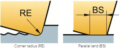
To generate the best milling surface finish, it is important to ensure that the feed per revolution (fn = fz x zn) is less than 80% of BS.
The number of teeth and feed per revolution increase as cutter diameter grows (especially for extremely close pitch cutters), necessitating a larger BS. The axial run-out of the cutter will impact the surface finish as soon as the feed per revolution exceeds the width of this land.
For best milling surface finish, use:
- Wiper inserts or milling inserts with BS at least 25% larger than fn
- Cermet inserts for a mirror finish
- Cutting fluid to avoid smearing
Wiper inserts
Finishing in bigger diameters is possible with a wiper, or lengthy parallel land. The wiper is placed below the conventional inserts to ensure that the surface is generated by this insert. The maximum fn should not exceed 80% of the BS.

Round inserts
Although round inserts and inserts with a big corner radius are incredibly prolific, they do not provide a high-quality surface. The worse the surface polish, the greater the cutter diameter.
Q7) What are Radially Generated surfaces?
A7)
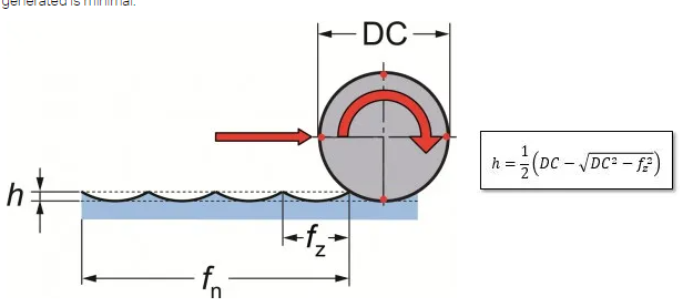
A radial surface is created when an end mill, shoulder mill, or side and face mill cutter is used. The side of the tool that generates the profile on a radial produced surface is the side of the tool that generates the profile.
Each tooth generates a cusp (h), the width of which is defined by the relationship between the cutter diameter and fz, and the depth of which is dictated by the relationship between the cutter diameter and fz. The cusp created theoretically has a small size.
Q8) What are the Parts Used in Indexing Mechanism?
A8)
Indexing Plate – The indexing plate is a circular plate with holes that are evenly spaced. An indexing plate must have at least 6 holes. This indexing plate is attached to a crank, which in turn is attached to a handle. In the Simple Indexing Mechanism, this indexing plate is stationary, but it can move in the Differential Indexing Mechanism.
Crank – This crank has a handle that is manually rotated to give the worm shaft and worm the initial rotation, which is then transferred to the worm wheel.
Crank Pin – Crank Pins are used to keep the crank from rotating. The crank pin is put into the entire indexing plate, which is stationary and does not rotate, locking the crank's rotation.
Worm Shaft – The crank is connected to this shaft, which revolves with it. It is the link between the crank and the worm.
Worm – The worm shaft connects the worm to the crank. This worm has a threaded screw-like appearance. It's a worm with only one thread. When the crank is rotated using handle this worm also rotates due to rotation of worm shaft and a single tooth in worm wheel which is connected to the worm passes through the worm.
Worm Wheel (W.W) – The worm wheel has teeth that resemble gears. When the entire worm wheel's teeth have passed through the worm. One spin of the worm wheel is completed.
Spindle - The worm wheel is attached to the spindle, which revolves in tandem with it. When all the teeth of worm wheel pass through the worm, this worm wheel completes one rotation and the spindle connected to the worm wheel also completes one rotation. The face plate connects the spindle to the plate.
Face Plate – This face plate is attached to the spindle and revolves in tandem with the spindle. The workpiece is attached to this face plate, and the workpiece rotates with the face plate.
Change Gears – These gears are employed in differential indexing mechanisms to allow the indexing plate to rotate forward or backward as needed. These gears are attached to the worm wheels and take the rotation of the worm wheel as input and output to the indexing plate.
Q9) Explain Hydraulic Drive.
A9)
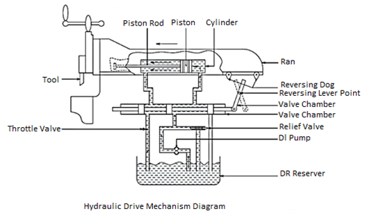
The hydraulic drive has a reciprocating piston inside the hydraulic cylinder. Between the ram and the piston lies the piston rod. As a result, the piston reciprocates with the ram.
There are two entries at the cylinder's end, as shown in the diagram. A control valve with four passages is installed below it.
The remaining two entries from the cylinder to the control valve are connected through a reservoir.
Q10) State the various types of headstocks used in capstan and turret lathes.
A10)
The following are the various types of headstocks used in capstan and turret lathes:
- Step cone pulley driven headstock.
- Direct electric motor driven headstock.
- All geared headstock.
- Preoptive or preselective headstock.
Step Cone Pulley Driven Headstock
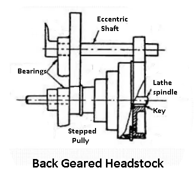
Small capstan lathes are fitted to this style of headstock, which is the most basic. When the lathe is used to process workpieces with a tiny and nearly constant diameter. Only three or four steps of the pulley can meet the machine's requirements.
Unlike an engine lathe, where the machine spindle may be started, stopped, and reversed by pushing a foot pedal, the machine requires a unique countershaft.
Electric Motor Driven Headstock
Both the machine's spindles and the motor's armature shaft are one and the same in an electric motor-driven headstock.
Direct control of the motor allows for any speed differential or reversal. Three or four are available, and the machine is designed for workpieces with smaller diameters that revolve at high speeds.
All Geared Headstock
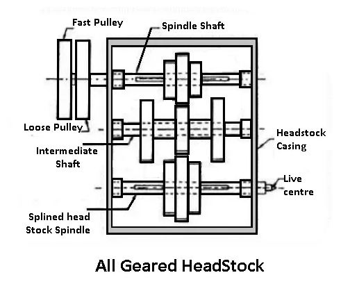
The headstocks on larger lathes are geared, and a separate mechanism is used to change the speed by actuating levers. The machine was not stopped while the speed was changed.
Preoptive or Preselective Headstock
It's an all-geared headstock with features like speedy stopping, starting, and speed charging for various tasks, as well as the ability to push a button or pull a lever.
The spindle speed must alter for different activities and for turning different diameters. The next operation's needed speed is chosen ahead of time. And the speed-changing lever has been set to the desired setting.
A button or a lever is simply actuated when the initial operation is completed. And, without stopping the machine, the spindle begins rotating at the set speed for the second operation. Friction clutches have an impact on this innovative mechanism.
Q11) What is Single spindle automatic lathe?
A13)
Single spindle automatic lathes are commonly used for quantity or mass production (by machining) of high quality fasteners, such as bolts, screws, studs, bushings, pins, shafts, rollers, handles, and other small metallic parts, from long bars or tubes of regular section, as well as from separate small blanks. A typical single spindle automatic lathe is shown in the diagram. Single spindle automats, unlike semiautomatic lathes, are:
• Preferably and basically utilised for large-scale production, such as huge lots and mass production.
• Always used to produce jobs that are rod, tube, or ring in nature and are of a smaller size.
• Run fully automatically, including bar feeding and tool indexing, over a lengthy period of time, repeating the same machining cycle for each product.
• Up to five radial tool slides are provided, which are moved by cams mounted on a cam shaft.
• Smaller in size and power, yet with faster spindle speeds
Q12) State advantages and disadvantages of gear shaping?
A14)
The following are the main benefits of the gear shaping process:
(a) Shorter product cycle time and suitability for mass manufacture of medium and large-sized gears.
(b) Other than worm and worm wheels, several sorts of gears can be manufactured.
(c) Gear cutting tolerances can be kept to a minimum.
(d) The gear tooth profile's accuracy and repeatability may be easily maintained.
(e) Regardless of the number of teeth in the gear, a single type of cutter can be employed for the same value of gear tooth module.
Disadvantages of gear shaping:
• Internal gears are not recommended.
• The gear shaper does not cut on the return stroke due to the reciprocating movement of the cutter.
Worms and worm wheels aren't possible to make with gear shapers.
• Due to periodic indexing, the rate of production is lower than the gear hobbing method.
• More machining time is required.
Q13) Explain Gear Shaping by Rack Shaped Cutter
A15)
A rack-shaped cutter called a rack type cutter is used to cut gear in this way. Figure depicts the principle in action. The working process is identical to that of a gear type cutter.
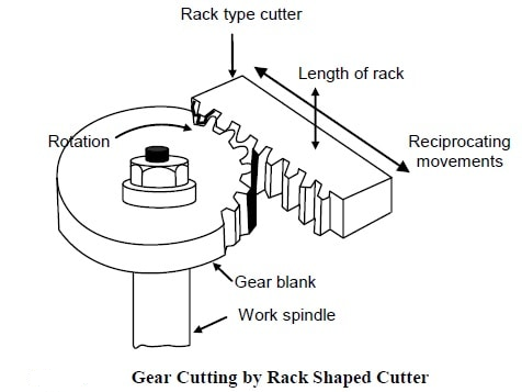
Gear Shaping by Rack Shaped Cutter
The gear blank is rotated (low rpm) as the rack type cutter reciprocates along a vertical line in this procedure. Only the downward stroke is used for cutting; the upward stroke is only a return action. The key difference between this procedure and the previous one is that once the entire length of the rack has been used, the gear cutting operation is halted in order to return the gear blank to its starting position, allowing another pass of gear cutting to begin. As a result, this technique is only used on occasion to cut bigger gears with a significant number of teeth around their edge.
Q14) How was the Lathe Machine Introduce?
A16)
The Lathe was invented by Jacques de Vaucanson around 1751.
The lathe machine is a centuries-old machine. This machine was built at a very early stage, circa 1300 BC, when there were not many pieces constructed except for the headstock and tailstock. Metalworking lathes, on the other hand, evolved into heavier machines with thicker, more solid elements during the industrial revolution.
Electric motors supplanted line shafting as a power source in the 19th and 20th centuries.
The servomechanism was then used to drive lathes and other machine tools using a numeric, direct numerical control machine in 1950.
The lathe is the most adaptable machine tool of all the conventional machine tools.
Nowadays, manually operated machines exist in the same way that CNC machines do, and the lathe machine can even run manually with the help of a feed mechanism.
Q15) What is Feed Machine?
A17)
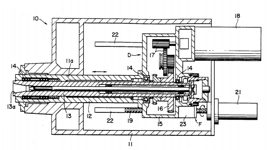
This invention relates to machine tools in general, and in particular to those with a spindle on which multiple cutting tools, arbours, and other attachments can be installed interchangeable. The innovation is more specifically a spindle head with a mechanism for feeding the spindle against work. Although no needless limits are envisaged, the spindle head according to the invention is well suited for use in boring machines.
Boring machine spindles are fed lengthwise out of the spindle head against the work. For a study of the traditional spindle feed mechanism, consider a horizontal boring and milling machine. The boring spindle has been received into a hollow milling spindle and is keyed or splined to the milling spindle for axial sliding movement. The boring spindle has been attached to a feed mechanism, such as a hydraulic actuator or a feed screw, for axially driving it with regard to the milling spindle. The milling spindle is rotated by a gear train connected to the boring spindle's drive motor.
The boring spindle was therefore fed out of the milling spindle during machining, according to the previous art. As a result, when the boring spindle was extended out of the milling spindle, it was supported effectively in a cantilever form. Of course, such cantilever support of the boring spindle is disagreeable since it is subjected to larger bending loads during machining due to the cutting tool placed to its distal end. The outcome has been easy deflection of the boring spindle under load, as well as subsequent cutting tool vibration. Because the boring spindle is easily deflected under its own weight, there are restrictions on the size and weight of cutting tools and attachments that can be placed to it.
The boring spindle has been free to experience axial deformation since it is slidable axially with regard to the milling spindle. This has caused an additional annoyance. The boring spindle has proved sensitive to thermal deflection as heat builds up during machining, reducing machining accuracy.
Q16) Define Lathe Machine?
A18)
A lathe machine is a machine tool that removes metal from a workpiece to give it the shape and size that you want.
Metalworking, woodturning, metal spinning, thermal spraying, glass working, and parts reclamation all employ lathe machines.
Sanding, cutting, knurling, drilling, and deformation of tools used in making symmetrical objects along the axis of rotation are some of the other activities that you may conduct with the help of a Lathe Machine.
A lathe is made up of various parts. It's also referred to as the "Father of All Standard Machine Tools."
The purpose of a lathe is to remove metal in the form of chips from a piece of work by rigidly mounting it on a machine spindle and rotating at the needed speed, while a cutting tool is fed against the work longitudinally or transverse to shape and size it to the appropriate shape and size.
Q17) State and explain different type of turning operation in lathe?
A19)
The process of removing surplus material from a workpiece in order to create a cone-shaped or cylindrical surface.
There are various different types of turning operations:
- Straight turning
- Shoulder turning
- Rough turning
- Finish turning
- Taper turning
- Eccentric turning
Straight turning:
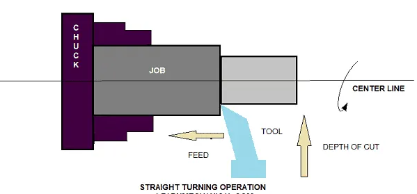
This operation is done to produce a cylindrical surface by removing excess material from the workpiece.
It is done in the following ways:
1. Secure the job with a suitable work holding device and verify that the job axis is parallel to the lathe axis.
2. Place the cutting tool on the tool post with the cutting edge parallel to or slightly above the work axis.
3. Adjust the spindle to the desired feed rate.
4. Determine the depth of cut based on the finish or rough cut.
5. Begin the machining process.
6. Activate automatic feed to move the carriage with the tool to the required length, then deactivate the feed to return the carriage to its original position.
7. The procedure is continued till the task is completed.
Shoulder turning:
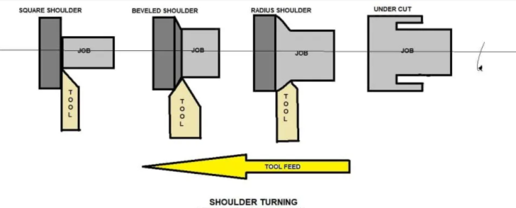
A shoulder turning is called which has a different diameter to form a step from one diameter to another.
The shoulder is divided into four types.
- Square
- Beveled
- Radius
- Undercut
Rough turning:
It is a process of removal of excess material from the workpiece in minimum time by applying a high rate of feed and heavy depth of cut.
The cut depth is 2 to 5mm, and the feed rate is 0.3 to 1.5mm each revolution.
Finish turning:
To achieve a smooth surface, the finish turning operation necessitates a high cutting speed, a low feed rate, and a very shallow depth of cut.
Finish turning has a cut depth of 0.5 to 1mm and a feed rate of 0.1 to 0.3 mm per revolution.

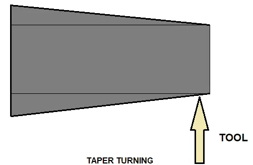
Taper turning:
A taper is described as a consistent drop or rise in a workpiece's diameter across its length.
Taper turning is the process of creating a conical surface with a steady reduction in diameter from a cylindrical object.
Q18) Explain Transfer Machines what are the types of transfer machines?
A20)
Metal working machine tools having multiple stations for executing diverse machining processes are known as transfer machines. Workpieces are loaded into the machine and indexed from station to station automatically. Each station conducts a distinct operation on the workpiece at the same time, and they leave the machine as a partially or fully finished unit. Multiple, sequential mechanical components, such as cutting heads, transfer devices, indexing tables, and work, make up standard transfer machine systems. Workpieces are indexed in a circular or linear path using stationary or mobile fixtures. Components flow through each work station during a cycle, performing particular machining procedures. The indexing table can move both continuously and intermittently and can turn vertically or horizontally. Transfer machines boost production rates when used in conjunction with an automated transfer line for part feeding.
Mass production of metal parts for a range of industries, such as the automotive and industrial machinery industries, is one application for transfer machines. For the production of discrete components, custom systems are available.
Types:
There are three primary types of transfer machines:
Rotary: Workpieces are moved between stations in a circular path by these machines. These systems are cost-effective because they can be mass-produced in a compact space. Due to lower labour costs, modern CNC-enabled flexible transfer machines of this type have gained appeal in European and North American domestic production facilities.
In-line or linear: Workpieces travel in a straight line from one workstation to the next. The number of axes a machine operates on, combined with the number of machining stations, determines the quantity and type of parts and processes the machine can perform.
Trunnion: The trunnion is a horizontal shaft that is used to index parts. The pieces rotate in a rotational manner similar to that of a Ferris wheel. Cutting tools simultaneously engage the pieces at their various stations, allowing each index to yield a finished item. The number of machining units is determined by the machine's size.
Secondary procedures, as well as associated tooling and manpower, are eliminated with CNC-enabled trunnions with the ability to alter their tooling. Newer trunnion transfer devices can process a workpiece axially on both ends. They can be fitted with vertical or angular supplemental tooling components to create a five-sided contact with the component during the machining process.