Question Bank
Unit - 3
- List type of perpendicular planes.
Ans:
(i) Perpendicular to both the reference planes.
(ii) Perpendicular to one plane and parallel to the other.
(iii) Perpendicular to one plane and inclined to the other.
2. Explain with a sketch what does perpendicular to both reference planes indicate.
Ans:
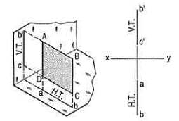
A square ABCD is perpendicular to both the planes. Its H.T. And V.T. Are in a straight-line perpendicular to xy.

Figure 1
The front view b'c' and the top view ab of the square are both lines coinciding with the V.T. And the H.T. Respectively.
3. Explain with a sketch what does perpendicular toone plane and parallel to the other plane indicate.
Ans:
a) Plane, perpendicular to the H.P. And parallel to the V.P. [fig.2(i)]. A triangle PQR is perpendicular to the H.P. And is parallel to the V.P. Its H.T. Is parallel to xy. It has no V.T.
The front view p'q'r' shows the exact shape and size of the triangle. The top view pqr is a line parallel to xy. It coincides with the H.T.
(b) Plane, perpendicular to the V.P. And parallel to the H.P. [fig. 2(ii)]. A square ABCD is perpendicular to the V.P. And parallel to the H.P. Its V.T. Is parallel to xy. It has no H.T.
The top view abed shows the true shape and true size of the square. The front view a'b' is a line, parallel to xy. It coincides with the V.T.

Figure 2
4. What are traces of planes?
Ans:
A plane, extended if necessary, will meet the reference planes in lines, unless it is parallel to any one of them.
These lines are called the traces of the plane. The line in which the plane meets the H.P. Is called the horizontal trace or the H.T. Of the plane. The line in which it meets the V.P. Is called its vertical trace or the V.T. A plane is usually represented by its traces.
a) When a plane is perpendicular to both the reference planes, its traces lie on a straight-line perpendicular to xy.
(b) When a plane is perpendicular to one of the reference planes, its trace upon the other plane is perpendicular to xy (except when it is parallel to the other plane).
(c) When a plane is parallel to a reference plane, it has no trace on that plane. Its trace on the other reference plane, to which it is perpendicular, is parallel to xy.
(d) When a plane is inclined to the H.P. And perpendicular to the V.P., its inclination is shown by the angle which its V.T. Makes with xy. When it is inclined to the V.P. And perpendicular to the H.P., its inclination is shown by the angle which its H.T. Makes with xy.
(e) When a plane has two traces, they, produced if necessary, intersect in xy (except when both are parallel to xy as in case of some oblique planes).
5. What is projection of planes?
Ans:
(a) When a plane is perpendicular to a reference plane, its projection on that plane is a straight line.
(b) When a plane is parallel to a reference plane, its projection on that plane shows its true shape and size.
(c) When a plane is perpendicular to one of the reference planes and inclined to the other, its inclination is shown by the angle which its projection on the plane to which it is perpendicular, makes with xy. Its projection on the plane to which it is inclined, is smaller than the plane itself.
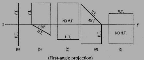
Problem 1. Show by means of traces, each of the following planes:
(a) Perpendicular to the H.P. And the V.P.
(b) Perpendicular to the H.P. And inclined at 30° to the V.P.
(c) Parallel to and 40 mm away from the V.P.
(d) Inclined at 45° to the H.P. And perpendicular to the V.P.
(e) Parallel to the H.P. And 25 mm away from it.

Figure 6
(a) The H.T. And the V.T. Are in a line perpendicular to xy.
(b) The H.T. Is inclined at 30° to xy; the V.T. Is normal to xy; both the traces intersect in xy.
(c) The H.T. Is parallel to and 40 mm away from xy. It has no V.T.
(d) The H.T. Is perpendicular to xy; the V.T. Makes 45° angle with xy; both intersect in xy.
(e) The V.T. Is parallel to and 25 mm away from xy. It has no H.T.
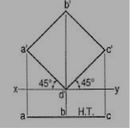
6. A square ABCD of 40 mm side has a corner on the H.P. And 20 mm in front of the V.P. All the sides of the square are equally inclined to the H.P. And parallel to the V.P. Draw its projections and show its traces.

Figure 8
As all the sides are parallel to the V.P., the surface of the square also is parallel to it. The front view will show the true shape and position of the square.
(i) Draw a square a'b'c'd' in the front view with one corner in xy and all its sides inclined at 45° to xy.
(ii) Project the top view keeping the line ac parallel to xy and 30 mm below it. The top view is its H.T. It has no V.T.
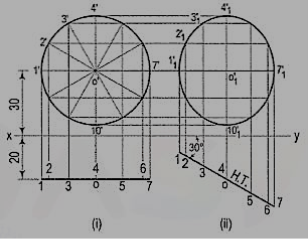
7. Draw the projections of a circle of 50 mm diameter, having its plane vertical and inclined at 30° to the V.P. Its center is 30 mm above the H.P. And 20 mm in front of the V.P. Show also its traces.

Figure 10
A circle has no corners to project one view from another. However, many points, say twelve, equal distances apart, may be marked on its circumference.
(i) Assuming the circle to be parallel to the V.P., draw its projections. The front view will be a circle [fig. 10 (i)], having its center 30 mm above xy. The top view will be a line, parallel to and 20 mm below xy.
(ii) Divide the circumference into twelve parts (with a 30°-60° set- square) and mark the points as shown. Project these points in the top view. The centre O will coincide with the point 4.
(iii) When the circle is tilted, to make 30° angle with the V.P., its top view will become inclined at 30° to xy. In the front view all the points will move along their respective paths (parallel to xy). Reproduce the top view keeping the centre o at the same distance, viz. 20 mm from xy and inclined at 30° to xy [fig. 10 (ii)].
(iv) For the final front view, project all the points upwards from this top view and horizontally from the first front view. Draw a freehand curve through the twelve points 1'1, 2'1 etc. This curve will be an ellipse.
8. What is auxiliary projection method?
Ans:
Two views of an object, viz. The front view and the top view (projected on the
Principal planes of projection), are sometimes not sufficient to convey all theinformationregarding the object. Additional views, called auxiliary views, are therefore, projectedon other planes known as auxiliary planes. These views are often found necessaryin technical drawings. Auxiliary views may also be used for determining
(i) the true length of a line,
(ii) the point-view of a line,
(iii) the edge-view of a plane,
(iv) the true size and form of a plane etc.
They are thus especially useful in finding solutions of problems in practical solid geometry.