Question Bank
Unit - 4
- List out methods of projections of solids in simple positions.
Ans:
(a) Axis perpendicular to the H.P.
(b) Axis perpendicular to the V.P.
(c) Axis parallel to both the H.P. And the V.P.
2. List out methods of Projections of solids with axes inclined to one of the reference planes and parallel to the other.
Ans:
(a) Axis inclined to the V.P. And parallel to the H.P.
(b) Axis inclined to the H.P. And parallel to the V.P.
3. What are various types of solids?
Ans:
Solids may be divided into two main groups:
(1) Polyhedra
(2) Solids of revolution.
Polyhedra: A polyhedron is defined as a solid bounded by planes called faces. When all faces are equal and regular, the polyhedron is said to be regular. There are seven regular polyhedra which may be defined as stated below:
(i) Tetrahedron (fig. 1): It has four equal faces, each an equilateral triangle.
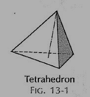
Figure 1
(ii) Cube or hexahedron (fig. 2): It has six faces, all equal squares.
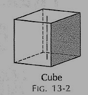
Figure 2
(iii) Octahedron (fig. 3): It has eight equal equilateral triangles as faces.
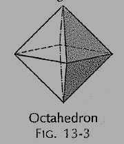
Figure 3
(iv) Dodecahedron (fig. 4): It has twelve equal and regular pentagons as faces.
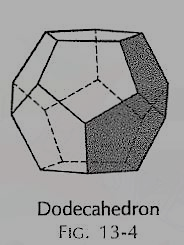
Figure 4
(v) Icosahedron (fig. 5): It has twenty faces, all equal equilateral triangles.

Figure 5
(vi) Prism: This is a polyhedron having two equal and similar faces called its ends or bases, parallel to each other and joined by other faces which are parallelograms. The imaginary line joining the centres of the bases is called the axis. A right and regular prism (fig. 6) has its axis perpendicular to the bases. All its faces are equal rectangles.
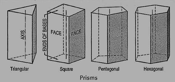
Figure 6
(vii) Pyramid: This is a polyhedron having a plane figure as a base and many triangular faces meeting at a point called the vertex or apex. The imaginary line joining the apex with the centre of the base is its axis.
A right and regular pyramid (fig. 7) has its axis perpendicular to the base which is a regular plane figure. Its faces are all equal isosceles triangles.
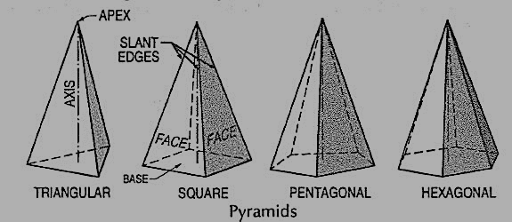
Figure 7
Oblique prisms and pyramids have their axes inclined to their bases. Prisms and pyramids are named according to the shape of their bases, as triangular, square, pentagonal, hexagonal etc.
4. What are solids of revolution?
Ans:
(i) Cylinder (fig. 8): A right circular cylinder is a solid generated by the revolution of a rectangle about one of its sides which remains fixed. It has two equal circular bases. The line joining the centres of the bases is the axis. It is perpendicular to the bases.
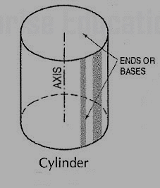
Figure 8
(ii) Cone (fig. 9): A right circular cone is a solid generated by the revolution of a right-angled triangle about one of its perpendicular sides which is fixed.
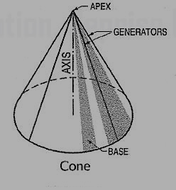
Figure 9
It has one circular base. Its axis joins the apex with the centre of the base to which it is perpendicular. Straight lines drawn from the apex to the circumference of the base-circle are all equal and are called generators of the cone. The length of the generator is the slant height of the cone.
(iii) Sphere (fig. 10): A sphere is a solid generated by the revolution of a semi-circle about its diameter as the axis. The mid-point of the diameter is the centre of the sphere. All points on the surface of the sphere are equidistant from its centre.
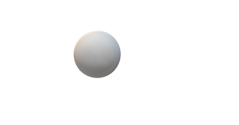
Figure 10
(iv) Frustum: When a pyramid or a cone is cut by a plane parallel to its base, thus removing the top portion, the remaining portion is called its frustum (fig. 11).
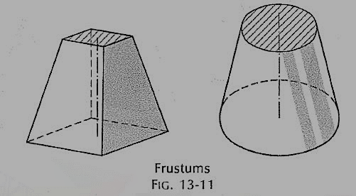
Figure 11
(v) Truncated: When a solid is cut by a plane inclined to the base it is said to be truncated.
5. Draw the projections of a triangular prism, base 40 mm side and axis 50 mm long, resting on one of its bases on the H.P. With a vertical face perpendicular to the V.P.

Figure 12
(i) As the axis is perpendicular to the ground i.e. the H.P. Begin with the top view. It will be an equilateral triangle of sides 40 mm long, with one of its sides perpendicular to xy. Name the corners as shown, thus completing the top view. The corners d, e and fare hidden and coincide with the top corners a, b and c respectively
(ii) Project the front view, which will be a rectangle. Name the corners. The line b'e' coincides with a'd'.
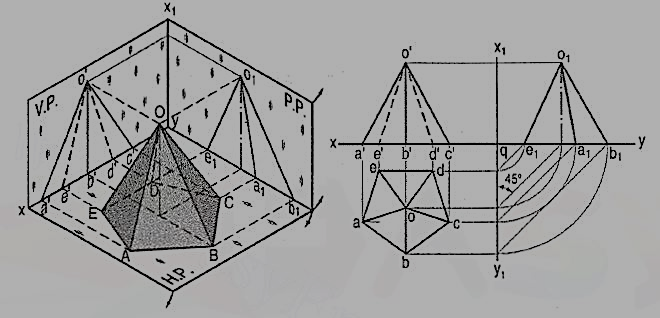
6. Draw the projections of a pentagonal pyramid, base 30 mm edge and axis 50 mm long, having its base on the H.P. And an edge of the base parallel to the V.P. Also draw its side view.
Figure 13
(i) Assume the side DE which is nearer the V.P., to be parallel to the V.P. As shown in the pictorial view.
(ii) In the top view, draw a regular pentagon abcde with ed parallel to and nearer xy. Locate its centre o and join it with the corners to indicate the slant edges.
(iii) Through o, project the axis in the front view and mark the apex o', 50 mm above xy. Project all the corners of the base on xy. Draw lines o'a', o'b' and o'c' to show the visible edges. Show o'd' and o'e' for the hidden edges as dashed lines.
(iv) For the side view looking from the left, draw a new reference line x1y1 perpendicular to xy and to the right of the front view. Project the side view on it, horizontally from the front view as shown. The respective distances of all the points in the side view from x1y1, should be equal to their distances in the top view from xy. This is done systematically as explained below:
(v) From each point in the top view, draw horizontal lines up to x1y1. Then draw lines inclined at 45° to x1y1 (or xy) as shown. Or, with q, the point of intersection between xy and x1y1 as centre, draw quarter circles. Project up all the points to intersect the corresponding horizontal lines from the front view and complete the side view as shown in the figure. Lines o1d1 and o1c1 coincide with o1e1 and o1a1 respectively.
7. A brass flower-vase is spherical in shape with flat, circular top 35 cm diameter and bottom 25 cm diameter and parallel to each other. The greatest diameter is 40 cm. Draw the projections of the vase when its axis is parallel to the V.P. And makes an angle of 60° with the ground. (fig. 24)
(i) Draw the front view of the vase resting on its bottom with its axis vertical. Project the top view.
(ii) Tilt the front view so that the axis makes 60° angle with xy and project the top view. Note that a part of the ellipse for the bottom is also visible.
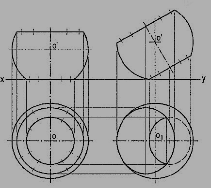
Figure 24
8. List various types of sectional planes.
Ans:
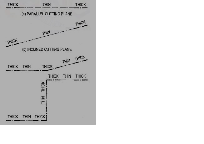
Section planes are generally perpendicular planes. They may be perpendicular to one of the reference planes and either perpendicular, parallel or inclined to the other plane. They are usually described by their traces. It is important to remember that the projection of a section plane, on the plane to which it is perpendicular, is a straight line. This line will be parallel, perpendicular or inclined to xy, depending upon the section plane being parallel, perpendicular or inclined respectively to the other reference plane.
9. A cube of 35 mm long edges is resting on the H.P. On one of its faces with a vertical face inclined at 30° to the V.P. It is cut by a section plane parallel to the V.P. And 9 mm away from the axis and further away from the V.P. Draw its sectional front view and the top view.
In fig.2 (i), the section plane is assumed to be transparent and the cube isshown with the cut-portion removed. Four edges of the cubeare cut and hence, the section is a figure having four sides.
Draw the projections of the whole cube in the required position [fig.2(ii)].As the section plane is parallel to the V.P., it is perpendicular to the H.P.;hence, the section will be a line in the top view coinciding with the H.T.of the section plane.
(i) Draw a line H.T. In the top view (to represent the section plane) paralleltoxy and 9 mm from o.
(ii) Name the points at which the edges are cut, viz. Ab at 1, be at 2, gf at 3 and fe at 4.
(iii) Project these points on the corresponding edges in the front view and join them in proper order.
As the section plane is parallel to the V.P., figure 1' 2' 3' 4' in the front view, shows the true shape of the section.
Show the views by dark but thin lines, leaving the lines for the cut-portion fainter.
(iv) Draw section lines in the rectangle for the section.
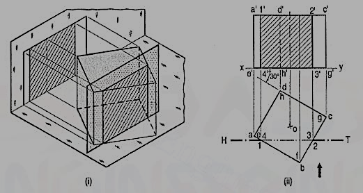
Figure 28