UNIT 7
Polyphase Circuits
- Explain the generation of three phase emf?
In a three – phase a.c. generator three coils are fastened rigidly together and displaced from each other by 1200. It is made to rotate about a fixed axis in a uniform magnetic field. Each coil is provided with a separate set of slip rings and brushes.
These voltages can be produced by a three-phase AC generator having three identical windings displaced separately from each other by 120 degrees electrical.
Three electrical circuits/coils are equally distributed over the margin of a permanent magnetic rotor. Three phase systems may or may not have an impartial wire. An impartial wire allows the three-phase structure to use a higher voltage while still sustaining lower voltage single phase appliances.
An emf is induced in each of the coils with a phase difference of 120o. Three coils a1 a2, b1 b2, and c1 c2 are mounted on the same axis but displaced from each other by 1200, and the coils rotate in the anticlockwise direction in a magnetic field
(Fig: a).
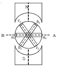
Fig; a Section of 3 phase ac generator
When the coil a1 a2 is in position AB, emf induced in this coil is zero and starts increasing in the positive direction. At the same instant, the coil b1b2 is 120o behind coil a1a2, so that emf induced in this coil is approaching its maximum negative value and the coil c1 c2 is 2400 behind the coil a1 a2, so the emf induced in this coil has passed its positive maximum value and is decreasing.
According to Faraday’s law, emf induced in three coils. The emf induced in these three coils will have phase dissimilarity of 1200. i.e. if the induced emf of the coil C1 has a phase of 00, then induced emf in the coil C2 lags that of C1 by 1200 and C3 lags that of C2 1200.
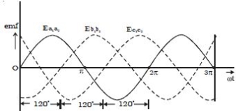
b Three phase emf
Thus, the EMFs induced in all the three coils are equal in magnitude and of the same frequency. The emf induced in the three coils are;
ea1a2 = E0 sin ωt
eb1b2 = E0 sin (ωt – 2π/3)
ec1c2 = E0 sin (ωt – 4π/3)
The emf induced and phase difference in the three coils a1 a1, b1 b1 and c1 c1 are shown in Fig: b & Fig:c.
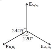
Fig: c Angular displacement between the armature
A three-phase method is equal if and only if:
- A load of each phase has equal impedance value;
- A load impedance of each phase has an equivalent phase angle;
- Voltage and current values are equivalent for each phase and;
- Phase disarticulation is 1200 between each phase.
2. Explain the phase sequence ?
- The order in which the three phase voltages attain their positive peak values is known as the phase sequence. Conventionally the three phases are designated as red-R, yellow-Y and blue-B phases.
- The phase sequence is said to be RYB if R attains its peak or maximum value first with respect to the reference as shown in the counter clockwise direction followed byY phase 120° later and B phase 240° later than the R phase.
- The phase sequence is said to be RBY if R is followed by B phase120° later and Y phase 240° later than the R phase. By convention RYB is considered as positive while the sequence RBY as negative.
- The phase sequence of the voltages applied to a load is determined by the order in which the 3 phase lines are connected.
- The phase sequence can be reversed by interchanging any one pair of lines without causing any change in the supply sequence. Reversal of sequence results in reversal of the direction of rotation in case of induction motor.
3. Explain the star and delta connection of three phase system?
Star and delta connection of three phase system:
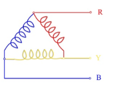
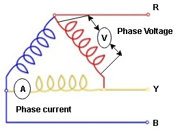
In a Star Connection, there are 4 wires: 3 phase wires and 1 neutral wire whereas in a Delta Connection, there are only 3 wires for distribution and all the 3 wires are phases (no neutral in a Delta connection).
The following image shows a typical Star and Delta Connection.
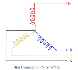
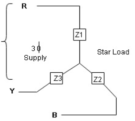
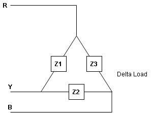
- Balanced load : balanced load is that in which magnitude of all impedance connected in the load are equal and the phase angle of them are also equal
Ie Z1  Z2
Z2  Z3 then it is unbalanced load
- Line values and phase Values :
- Line Values : ɡȴ RYB are supply lines then the voltage measured between any 2 Line is called as line voltage and current measured in the supply line is called as line current .
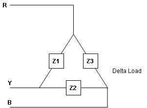
2. Phase Value : the voltage measured across a single winding or phase is called as phase voltage and the current measured on the single winding or phase is called as line current.
4.Derive the relation between line and phase voltage ?
Relation between line value and phase value of voltage and current for balanced (ʎ) star connected load (load can be resistive , Inductive or capacitive)
For capacitive load
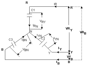
Consider a 3 Ø balanced star connected balanced load capacitive
- Line Value
Line voltage = VRY = VYB = VBR = VL
Line current = IR = IY = IB = IL
Phase value
Phase voltage = VRN = VYN = VBN = Vph
Phase current = VRN = VYN = VBN = Vph
Since for a balanced star connected load the line current is the same current flowing in the phase  the line current = phase current IR = IY = IB = IRN = IBN = IYN
 dor star connected load IN = Ipn
- Since the line voltage differ from phase voltage we can relate the line value of voltage with phase value of voltage
Referring current diagram
 =
=  +
+ 
Bar indicates vector addition
 =
= 
 =
=  -
-  …..①
…..①
Instead of writing  or
or  we can write VR and VY for practical purpose

Similarly other line voltage can be writing as follows.
(Resultant)
 =
=  -
-  …..②
…..②

 =
=  -
- 
5.Explain the phasor diagram?
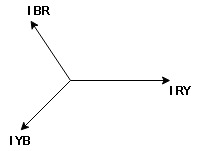
: we are getting resultant line current IR by subtracting 2 phase currents IRY and IBR  take phase currents at reference as shown
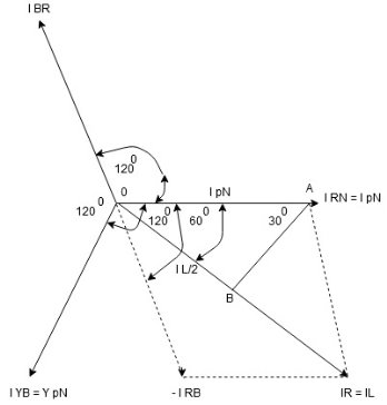
Cos 300 = 
 =
= 

- Complete phases diagram for delta connected balanced Inductive load.
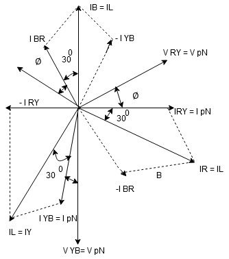
Phase current IYB lags behind VYB which is phase voltage as the load is inductive
6. Explain the power relation ?
PPh = VPh IPh Cos Ø
For 3 Ø total power is
PT= 3 VPh IPh Cos Ø …….①
For star
VL and IL = IPh (replace in ①)
 PT = 3
  IL Cos Ø
 PT = 3
  VL IL Cos Ø – watts
For delta
VL = VPh and IL =  (replace in ①)
PT = 3VL
= 3VL  Cos Ø
Cos Ø
 PT
PT VL IL Cos Ø – watts
Total average power
P =  VL IL Cos Ø – for ʎ and
  load
load
K (watts)
Total reactive power
Q =  VL IL Sin Ø – for star
  delta load
K (VAR)
Total Apparent power
S =  VL IL – for star
  delta load
K (VA)
- Power triangle
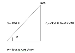
- Relation between power
In star and power in delta
Consider a star connected balance load with per phase impedance ZPh
We know that for
VL = VPh andVL =  VPh
VPh
Now IPh = 
 VL = =
And VPh = 
 IL =
IL =  ……①
……①
Pʎ =  VL IL Cos Ø ……②
Replacing ① in ② value of IL
 Pʎ =
Pʎ =  VL IL
VL IL  Cos Ø
Cos Ø
 Pʎ =
Pʎ =  ….A
….A
- Now for delta
IPh = 
 IPh = =
And IL =  IPh
IPh
 IL =
IL =  X
X  …..①
…..①
P =
=  VL IL Cos Ø ……②
Replacing ② in ① value of IL
P =
=  Cos Ø
Cos Ø
 P
P =
=  …..B
…..B

Pʎ from …A
 …..C
…..C
 =
=  P
P
We can conclude that power in delta is 3 time power in star from …C
Or
Power in star is  time power in delta from ….D
7. Explain the steps to solve delta and star problems ?
- Step to solve numerical
- Calculate VPh from the given value of VL by relation
For star VPh = 
For delta VPh = VL
2. Calculate IPh using formula
IPh = 
3. Calculate IL using relation
IL = IPh - for star
IL =  IPh - for delta
4. Calculate P by formula (active power)
P =  VL IL Cos Ø – watts
5. Calculate Q by formula (reactive power)
Q =  VL IL Sin Ø – VAR
6. Calculate S by formula (Apparent power)
S =  VL IL– VA
8.Explain the advantages of star and delta connections of three phase ?
- Greater power density
- Cost lower
- Easier to balance loads
- Minimizes harmonic currents
- Optimizes utilization of electrical capacity.
9. What is the importance of star and delta connections of three phase ?
Star configuration is better suited for carrying votages over long distances and since it has availability of neutral point through which any unbalanced or fault current may be grounded which makes star better to use for Distribution purposes Delta config on the other hand can carry balanced 3ph voltage without any neutral point which makes delta find use for Transmission systems
10. What are the disadvantages of star and delta transformations of three phase ?
In this type of connection, the secondary voltage is not in phase with the primary. Hence it is not possible to operate this connection in parallel with star-star or delta-delta connected transformer.
One problem associated with this connection is that the secondary voltage is shifted by 300 with respect to the primary voltage. This can cause problems when paralleling 3-phase transformers since transformers secondary voltages must be in-phase to be paralleled. Therefore, we must pay attention to these shifts.
If secondary of this transformer should be paralleled with secondary of another transformer without phase shift, there would be a problem.