UNIT 4
UNIT 4
Electromagnetism
- What is magnetic field ?
The magnetic field is a vector having both direction and magnitude. We denote the magnetic field with symbol  . The unit for the magnetic field is telsa.
|tesla| = |T=1N/A.m
Given a charge q moving with a velocity v in a magnetic field it is found that there is a force on the charge
This force is
Proportional to the charge q
Proportional to the speed v
Perpendicular to both v and B
Proportional to sin ɸ where ɸ is the angle between v abd B.
This can be summarized as
 = q .
= q .  x
x 
2. Explain its direction and characteristics?
A magnetic force experienced around the region of a magnet is called magnetic field. The characteristics of magnetic field lines are as follows:
(i) The magnetic field lines of a magnet start from the North Pole(N) and reach the South Pole(S) and these lines are in the north-south direction inside the magnet.
(ii) The region in which the field lines are at close distance to each other has a strong magnetic field and if the field lines are at far distance from each other, the region has a weak magnetic field. Near the poles of a magnet, the field lines are at close distance from each other so there is strong magnetic field.
(iii) The magnetic field is a very vector quantity. So it has magnitude and direction both. The tangent is drawn at any point of a magnetic field line.
(iv) Magnetic field lines do not intersect each other.

3. Explain magnetic flux density?
The magnetic flux density B describes the density and direction of the field lines that run through an area A. The denser the field lines, the larger the magnetic flux density, which is measured in tesla (T).
Magnetic flux Φ
The magnetic flux Φ is the magnetic flux density which runs through an imagined area.
If the field lines run in a straight line (e.g. Between the poles of a horseshoe magnet), the magnetic flux Φ through a certain area A which runs vertically to the flux can be calculated as follows:
Φ = B•A
The unit is Tm².

4. Define magnetomotive force?
The current flowing in an electric circuit is due to the existence of electromotive force similarly magnetomotive force (MMF) is required to drive the magnetic flux in the magnetic circuit. The magnetic pressure, which sets up the magnetic flux in a magnetic circuit is called Magnetomotive Force.
The SI unit of MMF is Ampere-turn (AT), and their CGS unit is G (gilbert).
The MMF for the inductive coil shown in the figure below is expressed as

Where, N – numbers of turns of the inductive coil
I – current.
5. What is magnetic field strength?
Magnetic field strength refers to the ratio of the MMF which is required to create a certain Flux Density within a certain material per unit length of that material.
The unit of magnetic field strength happens to be ampere per meter or A/m.
The magnetic field magnitude is:
B = μ0I/2πr
B = magnetic field magnitude (Tesla,T)
μ0 = permeability of free space 4μ×10−7T.mA) 4μ×10−7T.mA)
I = magnitude of the electric current ( Amperes)
r = distance(m)
6.Calculate the magnetic field strength inside a solenoid which is 2 m long and has 2000 loops. Furthermore, it carries a 1600 A current?
In order to find the magnetic field strength inside the solenoid, one must use
B = μ0Ni
Furthermore, one must note the number of loops per unit length:
n = N/ι = 2000/2 = 1000m-1 = 10 cm-1.
Now, one must substitute known values
B = μ0Ni = (4π10−7T.m/A)(1000m−1)(1600A)
= 2.01 T.
7.Explain Faraday’s law of electromagnetic induction?
- First law: whenever flux linkage with the coil changes an emf is induced in that conductor
- Second law: the magnitude of induced emf is equal to the rate of change of flux linkage.
Suppose a coil has n turns and flux through it change from initial value of Ø1 to Ø2 in line t sec
Initial flux linkage = N Ø
Final flux linkage = NØ2
 Induced emf e =
Putting the above equation in differential form
e = rate of change of flux linkage

8. Explain Fleming left hand rule ?
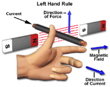
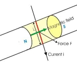
Whenever a current carrying conductor is placed inside a magnetic field, a force acts on the conductor, in a direction perpendicular to both the directions of the current and the magnetic field.
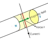
In the figure below, a portion of a conductor of length ‘L’ is placed vertically in a uniform horizontal magnetic field of strength ‘H’, produced by two magnetic poles N and S.
If the current ‘I’ is flowing through this conductor, the magnitude of the force acting on the conductor is:
F = B i L ------------------------------------(1)
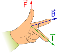
Hold out your left hand with the forefinger, second finger and thumb at the right angle to one another. The forefinger represents the direction of the field and the second finger represents that of the current, then thumb gives the direction of the force.
9. What is Fleming right hand rule ?

The thumb indicates the direction of the motion, the fore finger indicates the direction of the magnetic field and the middle finger represents the direction of the induced current.
According to Faraday’s law of electromagnetic induction, when a moving conductor is placed inside a magnetic field, a current will be induced in it.
If the conductor is forcefully moved inside the magnetic field, there will be a relationship between the direction of applied force, magnetic field and the current. This relation between these three directions is determined by Fleming’s right-hand rule.
10. Explain Lenz’s law ?
The direction of this induced emf is given by lenz’s law which states the polarity of induced emf is always such that it tends to set up a current which flow in such a direction so as to oppose the cause that produces it.

Whenever flux linking a conductor changes an emf is induced in it. This change in flux linkage can be trough about in the following 2 ways
- The conductor is moved in a stationary magnetic field in such a way that the flux linking is changes in magnitude.
The emf induced in this is called dynamically induced emf.
2. The conductor is stationary and magnetic field is moving or changing the emf induced in this way is called statically induced emf.
11. Explain force on a current carrying conductor ?
When a conductor carrying a current is placed in a magnetic field, the conductor experiences a magnetic force.
- The direction of this force is always right angles to the plane containing both the conductor and the magnetic field, and is predicted by Fleming’s Left-Hand Rule.
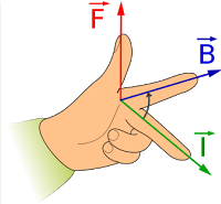
Referring to the diagram above, F is Force, B is Magnetic field, I is current.
Factors affecting magnetic force on a current-carrying conductor in a magnetic field:
- Strength of the magnetic field
- Current flowing through the wire
- Length of the wire
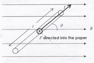
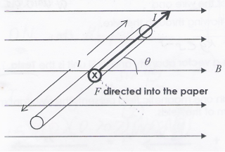
F=BI l sin θ, where
- F is force acting on a current carrying conductor, B is magnetic flux density (magnetic field strength),
- I is magnitude of current flowing through the conductor,
- l is length of conductor,
- θ is angle that conductor makes with the magnetic field.
When the conductor is perpendicular to the magnetic field, the force will be maximum. When it is parallel to the magnetic field, the force will be zero.
12. Explain self and mutual inductance?
Self-Induced EMF

Consider a coil haring n Turns carrying a current I amperes the current in the coil changes the flux linkage of the coil also changes which sets up a self-induced EMF in the coil
We know that
Ø x I
 Ø = K I

As  = K x I
Rate of flux linkage = K x rate of changes of current
 = K x
= K x
Now e = - N
Put value of  in above equation.
 e = - N k
 e = - N x
 x
x 
 K =
K = 
 e = - L
Where L =  = self Inductance
The property of coil that opposes any changes in the amount of current flowing through it is called as self - Inductance.
Mutually Induced EMF
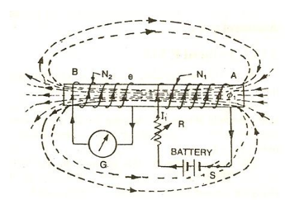
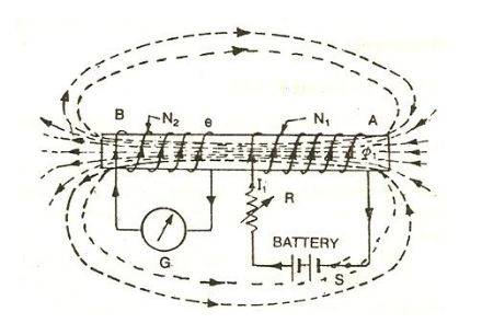
The emf induced in the coil due to change in current in the neighbouring coil is called as mutually induced EMF
Consider 2 coil 1 and 2 placed closed, adjacent to each other
Current  1 (Variable current) flows in coil 1, flux Ø1 is set up and a part of this flux (Ø2) links coil 2.
The EMF induced in coil 2 is termed as mutually induced EMF whereas EMF induced in coil 1 is termed as self-induced EMF.
Mutually induced emf is given by
e2 = -N2 
We know that Ø2 x  1
1
Ø2=K 1and k =
Rate of change of flux in coil 2 = k x change in current in coil 1
 = K
= K 
Now e2 = - N2 
Replacing value of  in above eq. M
 e2 = - N2 K
 e2 = - N2 K
  x
x 
 e2= - M
Where
M =  mutual Inductance
13. What is co-efficient of coupling?
The fraction of magnetic flux produced by the current in one coil that links with the other coil is called the coefficient of coupling between the two coils. It is denoted by (k).
Two coils are taken coil A and coil B, when current flows through one coil it produces flux; the whole flux may not link with the other coil coupled, and this is because of leakage flux by a fraction (k) known as Coefficient Of Coupling.
14. Explain inductors in parallel circuit?
Inductors in Parallel Circuit
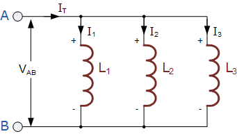
The total inductance, LT of the circuit was equal to the sum of all the individual inductors added together.
For inductors in parallel the equivalent circuit inductance LT is calculated differently.
The sum of the individual currents flowing through each inductor can be found using Kirchoff’s Current Law (KCL)
IT = I1 + I2 + I3 and the self-induced emf across an inductor is given as:
V = L di/dt
Then by taking the values of the individual currents flowing through each inductor in our circuit above, and substituting the current i for
i1 + i2 + i3
The voltage across the parallel combination is given as:
VAB = LT d/dt (i1+i2+i3)
= = LT di1/dt +di2/dt +di3/dt
By substituting di/dt in the above equation with v/L gives:
VAB = LT (v/L1 + v/L2 + v/L3)
15. Explain inductor in series ?

The current, ( I ) that flows through the first inductor, L1 has no other way to go but pass through the second inductor and the third and so on. Then, series inductors have a Common Current flowing through them, for example:
IL1 = IL2 = IL3 = IAB …etc.
In the example above, the inductors L1, L2 and L3 are all connected together in series between points A and B.
The sum of the individual voltage drops across each inductor can be found using Kirchoff’s Voltage Law (KVL) where,
VT = V1 + V2 + V3
The self-induced emf across an inductor is given as:
V = L di/dt.
So, by taking the values of the individual voltage drops across each inductor , the total inductance for the series combination is given as:
LT di/dt = L1 di/dt + L2 di/dt + L3 di/dt
16. Compare electric and magnetic field ?

UNIT 4
Electromagnetism
- What is magnetic field ?
The magnetic field is a vector having both direction and magnitude. We denote the magnetic field with symbol  . The unit for the magnetic field is telsa.
|tesla| = |T=1N/A.m
Given a charge q moving with a velocity v in a magnetic field it is found that there is a force on the charge
This force is
Proportional to the charge q
Proportional to the speed v
Perpendicular to both v and B
Proportional to sin ɸ where ɸ is the angle between v abd B.
This can be summarized as
 = q .
= q .  x
x 
2. Explain its direction and characteristics?
A magnetic force experienced around the region of a magnet is called magnetic field. The characteristics of magnetic field lines are as follows:
(i) The magnetic field lines of a magnet start from the North Pole(N) and reach the South Pole(S) and these lines are in the north-south direction inside the magnet.
(ii) The region in which the field lines are at close distance to each other has a strong magnetic field and if the field lines are at far distance from each other, the region has a weak magnetic field. Near the poles of a magnet, the field lines are at close distance from each other so there is strong magnetic field.
(iii) The magnetic field is a very vector quantity. So it has magnitude and direction both. The tangent is drawn at any point of a magnetic field line.
(iv) Magnetic field lines do not intersect each other.

3. Explain magnetic flux density?
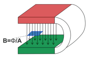
The magnetic flux density B describes the density and direction of the field lines that run through an area A. The denser the field lines, the larger the magnetic flux density, which is measured in tesla (T).
Magnetic flux Φ
The magnetic flux Φ is the magnetic flux density which runs through an imagined area.
If the field lines run in a straight line (e.g. Between the poles of a horseshoe magnet), the magnetic flux Φ through a certain area A which runs vertically to the flux can be calculated as follows:
Φ = B•A
The unit is Tm².
4. Define magnetomotive force?
The current flowing in an electric circuit is due to the existence of electromotive force similarly magnetomotive force (MMF) is required to drive the magnetic flux in the magnetic circuit. The magnetic pressure, which sets up the magnetic flux in a magnetic circuit is called Magnetomotive Force.
The SI unit of MMF is Ampere-turn (AT), and their CGS unit is G (gilbert).
The MMF for the inductive coil shown in the figure below is expressed as

Where, N – numbers of turns of the inductive coil
I – current.
5. What is magnetic field strength?
Magnetic field strength refers to the ratio of the MMF which is required to create a certain Flux Density within a certain material per unit length of that material.
The unit of magnetic field strength happens to be ampere per meter or A/m.
The magnetic field magnitude is:
B = μ0I/2πr
B = magnetic field magnitude (Tesla,T)
μ0 = permeability of free space 4μ×10−7T.mA) 4μ×10−7T.mA)
I = magnitude of the electric current ( Amperes)
r = distance(m)
6.Calculate the magnetic field strength inside a solenoid which is 2 m long and has 2000 loops. Furthermore, it carries a 1600 A current?
In order to find the magnetic field strength inside the solenoid, one must use
B = μ0Ni
Furthermore, one must note the number of loops per unit length:
n = N/ι = 2000/2 = 1000m-1 = 10 cm-1.
Now, one must substitute known values
B = μ0Ni = (4π10−7T.m/A)(1000m−1)(1600A)
= 2.01 T.
7.Explain Faraday’s law of electromagnetic induction?
- First law: whenever flux linkage with the coil changes an emf is induced in that conductor
- Second law: the magnitude of induced emf is equal to the rate of change of flux linkage.
Suppose a coil has n turns and flux through it change from initial value of Ø1 to Ø2 in line t sec
Initial flux linkage = N Ø
Final flux linkage = NØ2
 Induced emf e =
Putting the above equation in differential form
e = rate of change of flux linkage

8. Explain Fleming left hand rule ?
Whenever a current carrying conductor is placed inside a magnetic field, a force acts on the conductor, in a direction perpendicular to both the directions of the current and the magnetic field.
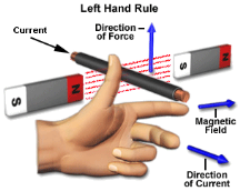
In the figure below, a portion of a conductor of length ‘L’ is placed vertically in a uniform horizontal magnetic field of strength ‘H’, produced by two magnetic poles N and S.
If the current ‘I’ is flowing through this conductor, the magnitude of the force acting on the conductor is:
F = B i L ------------------------------------(1)
Hold out your left hand with the forefinger, second finger and thumb at the right angle to one another. The forefinger represents the direction of the field and the second finger represents that of the current, then thumb gives the direction of the force.
9. What is Fleming right hand rule ?

The thumb indicates the direction of the motion, the fore finger indicates the direction of the magnetic field and the middle finger represents the direction of the induced current.
According to Faraday’s law of electromagnetic induction, when a moving conductor is placed inside a magnetic field, a current will be induced in it.
If the conductor is forcefully moved inside the magnetic field, there will be a relationship between the direction of applied force, magnetic field and the current. This relation between these three directions is determined by Fleming’s right-hand rule.
10. Explain Lenz’s law ?
The direction of this induced emf is given by lenz’s law which states the polarity of induced emf is always such that it tends to set up a current which flow in such a direction so as to oppose the cause that produces it.

Whenever flux linking a conductor changes an emf is induced in it. This change in flux linkage can be trough about in the following 2 ways
- The conductor is moved in a stationary magnetic field in such a way that the flux linking is changes in magnitude.
The emf induced in this is called dynamically induced emf.
2. The conductor is stationary and magnetic field is moving or changing the emf induced in this way is called statically induced emf.
11. Explain force on a current carrying conductor ?
When a conductor carrying a current is placed in a magnetic field, the conductor experiences a magnetic force.
- The direction of this force is always right angles to the plane containing both the conductor and the magnetic field, and is predicted by Fleming’s Left-Hand Rule.
Referring to the diagram above, F is Force, B is Magnetic field, I is current.
Factors affecting magnetic force on a current-carrying conductor in a magnetic field:
- Strength of the magnetic field
- Current flowing through the wire
- Length of the wire
F=BI l sin θ, where
- F is force acting on a current carrying conductor, B is magnetic flux density (magnetic field strength),
- I is magnitude of current flowing through the conductor,
- l is length of conductor,
- θ is angle that conductor makes with the magnetic field.
When the conductor is perpendicular to the magnetic field, the force will be maximum. When it is parallel to the magnetic field, the force will be zero.
12. Explain self and mutual inductance?
Self-Induced EMF

Consider a coil haring n Turns carrying a current I amperes the current in the coil changes the flux linkage of the coil also changes which sets up a self-induced EMF in the coil
We know that
Ø x I
 Ø = K I

As  = K x I
Rate of flux linkage = K x rate of changes of current
 = K x
= K x
Now e = - N
Put value of  in above equation.
 e = - N k
 e = - N x
 x
x 
 K =
K = 
 e = - L
Where L =  = self Inductance
The property of coil that opposes any changes in the amount of current flowing through it is called as self - Inductance.
Mutually Induced EMF
The emf induced in the coil due to change in current in the neighbouring coil is called as mutually induced EMF
Consider 2 coil 1 and 2 placed closed, adjacent to each other
Current  1 (Variable current) flows in coil 1, flux Ø1 is set up and a part of this flux (Ø2) links coil 2.
The EMF induced in coil 2 is termed as mutually induced EMF whereas EMF induced in coil 1 is termed as self-induced EMF.
Mutually induced emf is given by
e2 = -N2 
We know that Ø2 x  1
1
Ø2=K 1and k =
Rate of change of flux in coil 2 = k x change in current in coil 1
 = K
= K 
Now e2 = - N2 
Replacing value of  in above eq. M
 e2 = - N2 K
 e2 = - N2 K
  x
x 
 e2= - M
Where
M =  mutual Inductance
13. What is co-efficient of coupling?
The fraction of magnetic flux produced by the current in one coil that links with the other coil is called the coefficient of coupling between the two coils. It is denoted by (k).
Two coils are taken coil A and coil B, when current flows through one coil it produces flux; the whole flux may not link with the other coil coupled, and this is because of leakage flux by a fraction (k) known as Coefficient Of Coupling.
14. Explain inductors in parallel circuit?
Inductors in Parallel Circuit
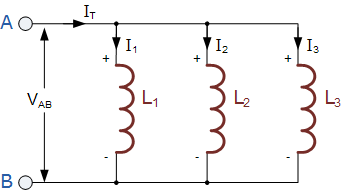
The total inductance, LT of the circuit was equal to the sum of all the individual inductors added together.
For inductors in parallel the equivalent circuit inductance LT is calculated differently.
The sum of the individual currents flowing through each inductor can be found using Kirchoff’s Current Law (KCL)
IT = I1 + I2 + I3 and the self-induced emf across an inductor is given as:
V = L di/dt
Then by taking the values of the individual currents flowing through each inductor in our circuit above, and substituting the current i for
i1 + i2 + i3
The voltage across the parallel combination is given as:
VAB = LT d/dt (i1+i2+i3)
= = LT di1/dt +di2/dt +di3/dt
By substituting di/dt in the above equation with v/L gives:
VAB = LT (v/L1 + v/L2 + v/L3)
15. Explain inductor in series ?

The current, ( I ) that flows through the first inductor, L1 has no other way to go but pass through the second inductor and the third and so on. Then, series inductors have a Common Current flowing through them, for example:
IL1 = IL2 = IL3 = IAB …etc.
In the example above, the inductors L1, L2 and L3 are all connected together in series between points A and B.
The sum of the individual voltage drops across each inductor can be found using Kirchoff’s Voltage Law (KVL) where,
VT = V1 + V2 + V3
The self-induced emf across an inductor is given as:
V = L di/dt.
So, by taking the values of the individual voltage drops across each inductor , the total inductance for the series combination is given as:
LT di/dt = L1 di/dt + L2 di/dt + L3 di/dt
16. Compare electric and magnetic field ?
