UNIT 6
UNIT 6
Single Phase AC Series and Parallel Circuits
- Explain series R-L circuit?
Series R-L Circuit
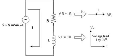
Consider a series R-L circuit connected across voltage source V= Vm sin wt
Like some, I is the current flowing through the resistor and inductor due do this current-voltage drops across R and L R  VR = IR and L
  VL = I X L
 Total V = VR + VL
V = IR + I X L  V = I [R + X L]


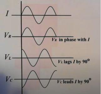
Take current as the reference phasor: 1) for resistor current is in phase with voltage 2) for Inductor voltage leads current or current lags voltage by 90 0.
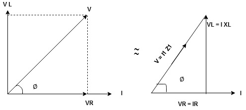
For voltage triangle
Ø is the power factor angle between current and resultant voltage V and
V = 

V = 

Where Z = Impedance of circuit and its value is  =
= 
Impedance Triangle
Divide voltage triangle by I
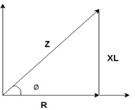
Rectangular form of Z = R+ixL
And polar from of Z =  L +
L + 
(+ j X L +  because it is in first quadrant )
Where  =
= 
 + Tan -1
Current Equation :
From the voltage triangle, we can sec. That voltage is leading current by  or current is legging resultant voltage by
Or i =  =
=  [ current angles - Ø )

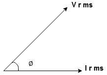
Resultant Phasor Diagram form Voltage and current eqth.
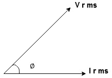
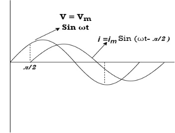
Waveform
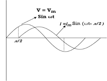
Power equation
P = V .I.
P = Vm Sin wt Im Sin wt – Ø
P = Vm Im (Sin wt) Sin (wt – Ø)
P =  (Cos Ø) - Cos (2wt – Ø)
Since 2 sin A Sin B = Cos (A-B) – Cos (A+B)
P =  Cos Ø -
  Cos (2wt – Ø)

①②
Average Power
Pang =  Cos Ø
Cos Ø
Since ② term becomes zero because Integration of cosine come from 0 to 2ƛ
 pang = Vrms Irms cos Ø watts.
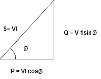
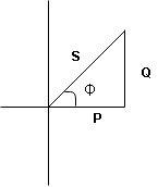
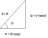
Power Triangle :
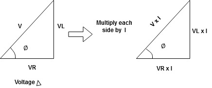
From 
VI = VRI + VLI B
Now cos Ø in  A =
A = 
 ①
①
Similarly Sin  =
= 


Apparent Power Average or true Reactive or useless power
Or real or active
-Unit (VI) Unit (Watts) C/W (VAR) denoted by (Ø)
Denoted by [S] denoted by [P]
Power  for R L ekt.
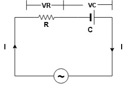
2. Explain series RC circuit ?
V = Vm sin wt
VR

 I
I
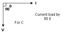
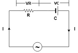
- Consider a series R – C circuit in which resistor R is connected in series with capacitor C across an ac voltage so use V = VM Sin wt (voltage equation).
- Assume current I is flowing through
R and C  voltage drop across.
R and C  R
R  VR = IR
And C  Vc = I
 c
c


 V =
V =  lZl
lZl
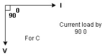
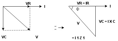
Voltage triangle: take current as the reference phasor 1) for resistor current is in phase with voltage 2) for capacitor current leads voltage or voltage lags behind current by 900
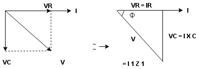
Where Ø is the power factor angle between current and voltage (resultant) V
And from voltage
V = 
V = 
V = 
V =  lZl
lZl
Where Z = impedance of the circuit and its value is lZl = 
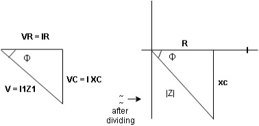
Impendence triangle :
Divide voltage  by
by  as shown
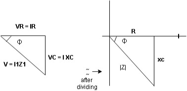
The rectangular form of Z = R - jXc
The polar form of Z = lZl L - Ø
( - Ø and –jXc because it is in the fourth quadrant ) where
LZl = 
And Ø = tan -1 
Current equation :
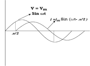
From voltage triangle we can see that voltage is lagging current by Ø or current is leading voltage by Ø
 i = IM Sin (wt + Ø) since Ø is +ve
Or i =  for RC
 LØ [ resultant current angle is + Ø]
Resultant phasor diagram from voltage and current equation

Resultant waveform :
Power Equation :
P = V. I
P = Vm sin wt. Im Sin (wt + Ø)
= Vm Im sin wt sin (wt + Ø)
2 Sin A Sin B = Cos (A-B) – Cos (A+B)
 -
- 
Average power
Pang =  Cos Ø
Cos Ø
Since 2 terms integration of cosine wave from 0 to 2ƛ become zero
 2 terms become zero
 pang = Vrms Irms Cos Ø
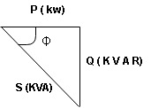
Power triangle RC Circuit:
3. Explain series R-L-C circuit ?
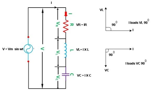
Consider ac voltage source V = Vm sin wt connected across the combination of R L and C. When I flowing in the circuit voltage drops across each component as shown below.
VR = IR, VL = I  L, VC = I
  C
C
- According to the values of Inductive and Capacitive Reactance, I e XL and XC decides the behavior of R-L-C series circuit according to following conditions
① XL> XC, ② XC> XL, ③ XL = XC
① XL > XC: Since we have assumed XL> XC
 The voltage drop across XL> than XC
 VL> VC A
- Voltage triangle considering condition A

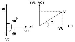
VL and VC are 180 0 out of phase.
Therefore cancel out each other
 Resultant voltage triangle
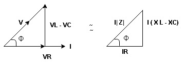
Now V = VR + VL + VC c phasor sum and VL and VC are directly in phase opposition and VL
 VC
VC their resultant is (VL - VC).
From voltage triangle
V = 
 V =
V = 
 V = I
V = I 

Impendence  : divide voltage
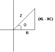
Rectangular form Z = R + j (XL – XC)
Polor form Z =  l + Ø B
Where  =
= 
And Ø = tan-1 
- Voltage equation : V = Vm Sin wt
- Current equation
i =  from B
i =  L-Ø C
L-Ø C
As VL VC the circuit is mostly inductive and
  I lags behind V by angle Ø
 Since i =
  L-Ø
L-Ø
 i = Im Sin (wt – Ø) from c
- XC
 XL :Since we have assured XC
  XL
XL
 the voltage drops across XC
  than XL
 XC
XC  XL (A)
 voltage triangle considering condition (A)
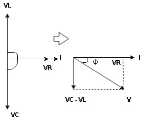
 Resultant Voltage
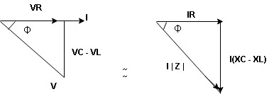
Now V = VR + VL + VC  phases sum and VL and VC are directly in phase opposition and VC
 VL
VL  their resultant is (VC – VL)
From voltage 
V = 
V = 
 V =
V = 
 V =
V = 

 Impedance
  : Divide voltage
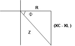
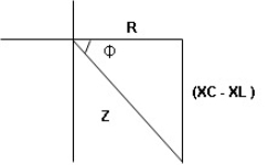
- Rectangular form : Z + R – j (XC – XL) – 4th qurd
Polar form : Z =  L -
L -
Where 
And Ø = tan-1 – 
- Voltage equation : V = Vm Sin wt
- Current equation : i =
 from B
 - i =
 L+Ø C
L+Ø C
As VC  the circuit is mostly capacitive and
  leads voltage by angle Ø
Since i =  L + Ø
L + Ø
 Sin (wt – Ø) from C
- Power
 :
:
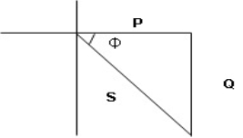
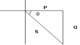
- XL= XC (resonance condition):
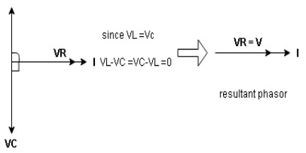
ɡȴ XL= XC then VL= VC and they are 1800 out of phase with each other  they will cancel out each other and their resultant will have zero value.
Hence resultant V = VR and it will be in phase with I as shown in the below phasor diagram.
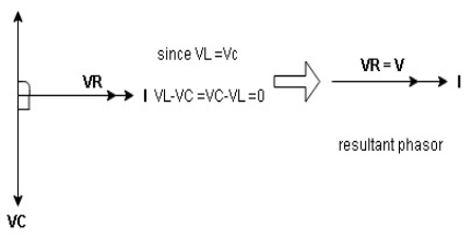
From the above resultant phasor diagram
V =VR + IR
Or V = I  lZl
lZl
Because lZl + R
Thus Impedance Z is purely resistive for XL = XC and circuit current will be in phase with source voltage.

 Since VR=V Øis zero when XL = XC
  power is unity
Ie pang = Vrms I rms cos Ø = 1 cos o = 1
Maximum power will be transferred by the condition. XL = XC
4. Explain bandwidth of series resonance circuit ?
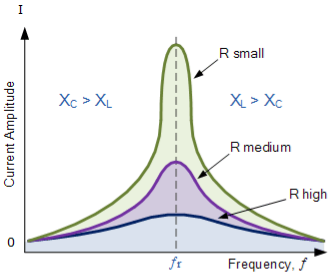
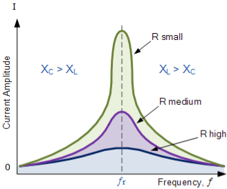
Then the relationship between resonance, bandwidth, selectivity and quality factor for a series resonance circuit being defined as:
1). Resonant Frequency, (ƒr)
XL = Xc
WrL -1/wrC =0
Wr2 = 1/LC ;
Wr = 1/ 
2). Current, (I)
At wr ZT =min Is = max
I max = Vmax/Z = Vmax/ [ R2 + (XL-Xc) 2 ] = Vmax / [ R2 +( wr L – 1/wrC )] ½
3). Lower cut-off frequency, (ƒL)
At half power , Pm/2 , I = Im/2 = 0.7071 Im
Z =  R , X = -R (capacitive)
wL = -R/2L + [ (R/2L) 2 + 1/LC] ½
4). Upper cut-off frequency, (ƒH)
At half power Pm/2 , I = Im /  = 0.7071 Im
Z =  R , X = +R (inductive)
wH = + R/2L + [ (R/2L) 2 + 1/LC] ½
5). Bandwidth, (BW)
BW = fr/Q ; fH – fL ; R/L rads or R/2 πL (Hz)
6). Quality Factor, (Q)
Q = wL/R = XL/R = 1/ wr CR = Xc/R = 1/R . [L/C] ½
5. What is quality factor ?
Quality factor, Q of the circuit. The quality factor relates the maximum or peak energy stored in the circuit (the reactance) to the energy dissipated (the resistance) during each cycle of oscillation meaning that it is a ratio of resonant frequency to bandwidth and the higher the circuit Q, the smaller the bandwidth,
Q = ƒr /BW.
6. Explain R-L-C parallel circuit?
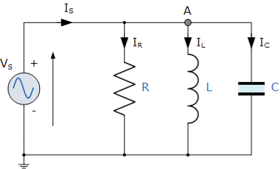
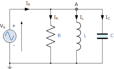
In the above parallel RLC circuit, the supply voltage, VS is common to all three components whilst the supply current IS consists of three parts. The current flowing through the resistor, IR, the current flowing through the inductor, IL and the current through the capacitor, IC.
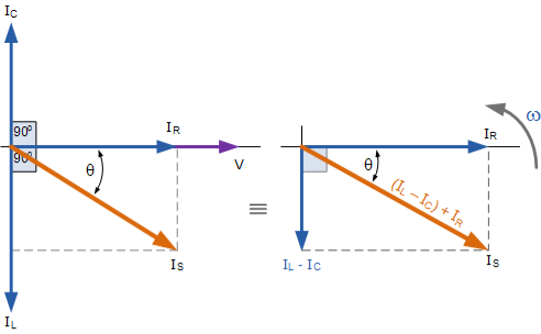
The phasor diagram for a parallel RLC circuit is produced by combining together the three individual phasors for each component and adding the currents vectorially.
Since the voltage across the circuit is common to all three circuit elements we can use this as the reference vector with the three current vectors drawn relative to this at their corresponding angles.
The resulting vector current IS is obtained by adding together two of the vectors, IL and IC and then adding this sum to the remaining vector IR.
The resulting angle obtained between V and IS will be the circuits phase angle as shown below.
Phasor Diagram for a Parallel RLC Circuit
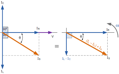
From the phasor diagram on the right hand side above that the current vectors produce a rectangular triangle, comprising of hypotenuse IS, horizontal axis IR and vertical axis IL – IC .
IS 2 = IR 2 + (IL – IC) 2
IS =[ IR 2 + (IL – IC) 2] ½
IS =[(V/R) 2 + (V/XL – V/XC) 2] ½ = V/Z
Since the voltage across the circuit is common to all three circuit elements, the current through each branch can be found using Kirchhoff’s Current Law, (KCL). Thus, the currents entering and leaving node “A” above are given as:
IS - IR -IL – IC = 0
IS – V/R – 1/L  dt – C dv/dt =0
Taking the derivative, dividing through the above equation by C and then re-arranging gives us the following Second-order equation for the circuit current.
It becomes a second-order equation because there are two reactive elements in the circuit, the inductor and the capacitor.
IS –d2 V/dt2 – dV/RC .dt – V/LC =0
IS (t) = d2V/dt 2 + dV/dt . 1/RC + 1/LC .V
The opposition to current flow in this type of AC circuit is made up of three components: XL XC and R with the combination of these three values giving the circuits impedance, Z.
7. Explain impedance of parallel RLC circuit?
R = V/IR XL = V/IL XC = V/IC
Z = 1/  ) 2 + (1/XL – 1/Xc) 2
Z =[ (1/R) 2 + (1/XL – 1/Xc) 2 ] ½
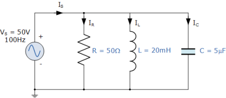
8.A 50Ω resistor, a 20mH coil and a 5uF capacitor are all connected in parallel across a 50V, 100Hz supply. Calculate the total current drawn from the supply, the current for each branch, the total impedance of the circuit and the phase angle. Also construct the current and admittance triangles representing the circuit.
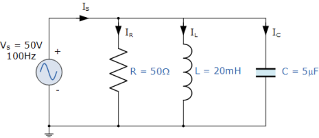
1). Inductive Reactance, ( XL ):
XL = wL = 2πfL = 2π . 100. 0.02 = 12.6 Ω
2). Capacitive Reactance, ( XC ):
Xc = 1/wC = 1/ 2πfC = 1/ / 2πx 100.5 x 10 -6 = 318.3 Ω
3). Impedance, ( Z ):
Z = 1/  (1/R) 2 + (1/Xc – 1/XL) 2 = 1/
  (1/50) 2 + ( 1/318.3 – 1/12.6)2
Z = 1/0.0788 = 12.7 Ω
4). Current through resistance, R ( IR ):
IR = V/R = 50/50 = 1A
5). Current through inductor, L ( IL ):
IL = V/XL = 50/12.6 = 3.9 A
6). Current through capacitor, C ( IC ):
IC = V/Xc = 50/ 318.3 = 0.16 (A)
7). Total supply current, ( IS ):
Is = [ IR 2 + (IL – IC) 2 ] ½ = [ 1 2 + (3.9 – 0.16) 2 ] ½ = 3.87 A
8). Conductance, ( G ):
G = 1/R = 1/50 = 20ms
9). Inductive Susceptance, ( BL ):
BL = 1/XL = 1/12.6 = 80ms
12). Phase Angle, ( φ ) between the resultant current and the supply voltage:
Cos ɸ = G/Y = 20ms/78ms = 0.256
ɸ = cos -1 0.256 = 75.3 (lag)
9.Explain bandwidth?
The bandwidth of a parallel resonance circuit is defined in exactly the same way as for the series resonance circuit. The upper and lower cut-off frequencies given as: ƒupper and ƒlower respectively denote the half-power frequencies where the power dissipated in the circuit is half of the full power dissipated at the resonant frequency 0.5( I2 R ) which gives us the same -3dB points at a current value that is equal to 70.7% of its maximum resonant value, ( 0.707 x I )2 R
BW = ƒr /Q or BW = ƒupper - ƒlower
10. Explain Q-factor?
Q-factor for a parallel resonance circuit is generally defined as the ratio of the circulating branch currents to the supply current and is given as:
Quality factor Q = R/ 2π fL = 2π f C R = R  C/L
C/L
11. Explain the solution to series and parallel circuits ?
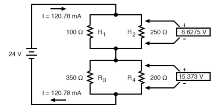
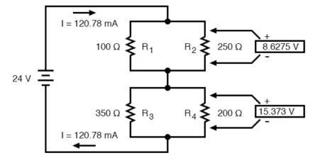
Consider the following circuit
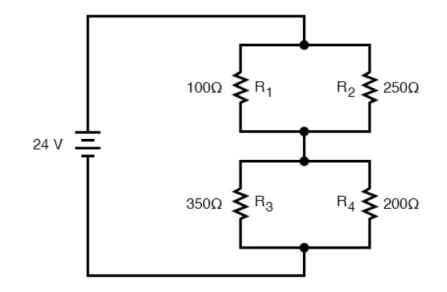
We can represent as

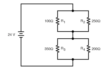
R1 and R2 are connected in a simple parallel arrangement, as are R3 and R4.
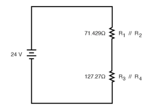

The final step in reduction is to add these two resistances to come up with a total circuit resistance. When we add those two equivalent resistances, we get a resistance of 198.70 Ω.
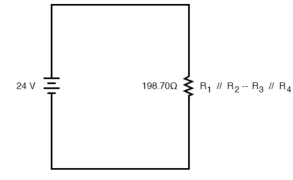

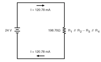
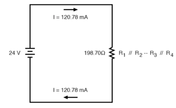
Now, total circuit current can be determined by applying Ohms law (I=E/R) to the “Total” column in the table:

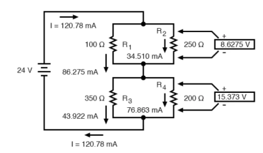
The total current value of 120.78 milliamps is shown as the only current here:
Knowing the current through the equivalent resistors R1//R2 and R3//R4, we can apply Ohm’s Law (E=IR) to the two right vertical columns to find voltage drops across them:
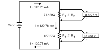

For the previous circuit

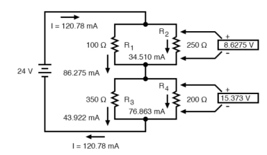
Applying Ohm’s Law to the remaining vertical columns (I=E/R), we can determine the currents through R1, R2, R3, and R4 individually:

Therefore,
12.A voltage in a circuit has the form
V(t) = 10 cos (2t-45) V
Find the corresponding phasor in polar and rectangular form.
Solution :
 = 10 cos (-45) + j 10 sin(-45)
= 10 cos 45 – j10 sin(45)
= 10 /  – j 10 /
= 5  - j 5
- j 5  V
V
13. Explain admittance method ?
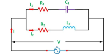
Admittance is defined as the effective ability of the circuit due to which it allows the alternating current to flow through it. It is represented by (Y). The old unit of admittance is mho (Ʊ). Its new unit is Siemens.
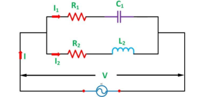
Step 1 – Draw the circuit as per the given problem.
Step 2 – Find the impedance and phase angle of each branch.
Z1 = [ R1 2 + X2 c1] ½ ɸ1 = tan-1 Xc1/R1
Z2 = [ R2 2 + X2 L2] ½ ɸ2 = tan-1 XL2/R2
Step 3 – Now, find Conductance, Susceptance and Admittance of each branch.
g 1 = R1 / Z1 2 ; b1 = Xc1/ Z1 2 (positive) ; Y1 = [ g1 2 + b1 2] ½
g2 = R2 / Z2 2 ; b2 = XL2/Z2 2 (negative ) ; Y2 = [ g2 2 + b2 2] ½
Step 4 – Find the algebraic sum of conductance and susceptance.
G = g1 + g2 ; B = b1 – b2
Step 5 – Find the total Admittance (Y) of the circuit.
Y = [ G2 + B2 ] ½
Step 6 – Find the various branch currents of the circuit.
I1 = VY1 and I2 = V Y2
Step 7 – Now, find the total current I of the circuit.
I = V Y
Step 8 – Find the phase angle of the whole circuit.
ɸ = tan -1 B/G
Phase angle will be lagging if B is negative.
Step 9 – Now, find the power factor of the circuit.
Power factor = cos ɸ = G/Y
14. Explain complex algebra method ?
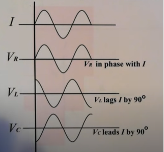
Complex numbers are used in AC circuits because resistors , capacitors and inductors (L) all react differently to AC current. The effective resistance of each element is called reactance.

Each element reacts differently to current. Thus, the AC voltage through each element either lags or leads the current.
Consider the following circuit :
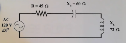
Z = [ 12 2 + 45 2 ]
Ɵ= tan -1 (12/45) = 15 0
Z = 46.57 < 15 0
UNIT 6
Single Phase AC Series and Parallel Circuits
- Explain series R-L circuit?
Series R-L Circuit
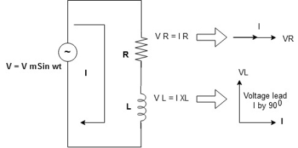
Consider a series R-L circuit connected across voltage source V= Vm sin wt
Like some, I is the current flowing through the resistor and inductor due do this current-voltage drops across R and L R  VR = IR and L
  VL = I X L
 Total V = VR + VL
V = IR + I X L  V = I [R + X L]


Take current as the reference phasor: 1) for resistor current is in phase with voltage 2) for Inductor voltage leads current or current lags voltage by 90 0.
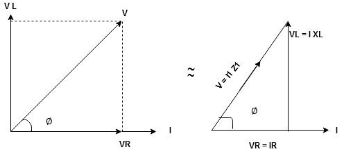
For voltage triangle
Ø is the power factor angle between current and resultant voltage V and
V = 

V = 

Where Z = Impedance of circuit and its value is  =
= 
Impedance Triangle
Divide voltage triangle by I
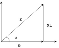
Rectangular form of Z = R+ixL
And polar from of Z =  L +
L + 
(+ j X L +  because it is in first quadrant )
Where  =
= 
 + Tan -1
Current Equation :
From the voltage triangle, we can sec. That voltage is leading current by  or current is legging resultant voltage by
Or i =  =
=  [ current angles - Ø )

Resultant Phasor Diagram form Voltage and current eqth.
Waveform
Power equation
P = V .I.
P = Vm Sin wt Im Sin wt – Ø
P = Vm Im (Sin wt) Sin (wt – Ø)
P =  (Cos Ø) - Cos (2wt – Ø)
Since 2 sin A Sin B = Cos (A-B) – Cos (A+B)
P =  Cos Ø -
  Cos (2wt – Ø)

①②
Average Power
Pang =  Cos Ø
Cos Ø
Since ② term becomes zero because Integration of cosine come from 0 to 2ƛ
 pang = Vrms Irms cos Ø watts.
Power Triangle :
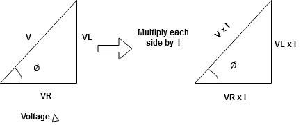
From 
VI = VRI + VLI B
Now cos Ø in  A =
A = 
 ①
①
Similarly Sin  =
= 


Apparent Power Average or true Reactive or useless power
Or real or active
-Unit (VI) Unit (Watts) C/W (VAR) denoted by (Ø)
Denoted by [S] denoted by [P]
Power  for R L ekt.
2. Explain series RC circuit ?
V = Vm sin wt
VR

 I
I
- Consider a series R – C circuit in which resistor R is connected in series with capacitor C across an ac voltage so use V = VM Sin wt (voltage equation).
- Assume current I is flowing through
R and C  voltage drop across.
R and C  R
R  VR = IR
And C  Vc = I
 c
c


 V =
V =  lZl
lZl
Voltage triangle: take current as the reference phasor 1) for resistor current is in phase with voltage 2) for capacitor current leads voltage or voltage lags behind current by 900
Where Ø is the power factor angle between current and voltage (resultant) V
And from voltage
V = 
V = 
V = 
V =  lZl
lZl
Where Z = impedance of the circuit and its value is lZl = 
Impendence triangle :
Divide voltage  by
by  as shown
The rectangular form of Z = R - jXc
The polar form of Z = lZl L - Ø
( - Ø and –jXc because it is in the fourth quadrant ) where
LZl = 
And Ø = tan -1 
Current equation :
From voltage triangle we can see that voltage is lagging current by Ø or current is leading voltage by Ø
 i = IM Sin (wt + Ø) since Ø is +ve
Or i =  for RC
 LØ [ resultant current angle is + Ø]
Resultant phasor diagram from voltage and current equation

Resultant waveform :
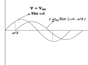
Power Equation :
P = V. I
P = Vm sin wt. Im Sin (wt + Ø)
= Vm Im sin wt sin (wt + Ø)
2 Sin A Sin B = Cos (A-B) – Cos (A+B)
 -
- 
Average power
Pang =  Cos Ø
Cos Ø
Since 2 terms integration of cosine wave from 0 to 2ƛ become zero
 2 terms become zero
 pang = Vrms Irms Cos Ø
Power triangle RC Circuit:
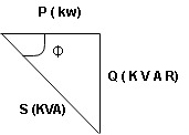
3. Explain series R-L-C circuit ?
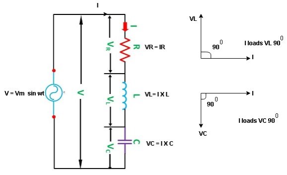
Consider ac voltage source V = Vm sin wt connected across the combination of R L and C. When I flowing in the circuit voltage drops across each component as shown below.
VR = IR, VL = I  L, VC = I
  C
C
- According to the values of Inductive and Capacitive Reactance, I e XL and XC decides the behavior of R-L-C series circuit according to following conditions
① XL> XC, ② XC> XL, ③ XL = XC
① XL > XC: Since we have assumed XL> XC
 The voltage drop across XL> than XC
 VL> VC A
- Voltage triangle considering condition A


VL and VC are 180 0 out of phase.
Therefore cancel out each other
 Resultant voltage triangle
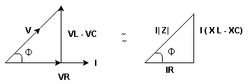
Now V = VR + VL + VC c phasor sum and VL and VC are directly in phase opposition and VL
 VC
VC their resultant is (VL - VC).
From voltage triangle
V = 
 V =
V = 
 V = I
V = I 

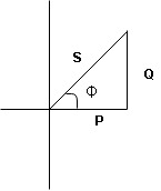
Impendence  : divide voltage
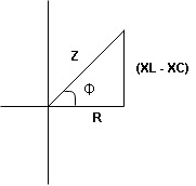
Rectangular form Z = R + j (XL – XC)
Polor form Z =  l + Ø B
Where  =
= 
And Ø = tan-1 
- Voltage equation : V = Vm Sin wt
- Current equation
i =  from B
i =  L-Ø C
L-Ø C
As VL VC the circuit is mostly inductive and
  I lags behind V by angle Ø
 Since i =
  L-Ø
L-Ø
 i = Im Sin (wt – Ø) from c
- XC
 XL :Since we have assured XC
  XL
XL
 the voltage drops across XC
  than XL
 XC
XC  XL (A)
 voltage triangle considering condition (A)
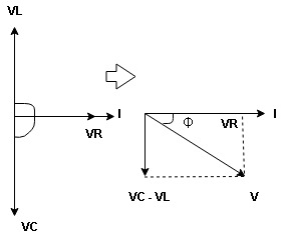
 Resultant Voltage
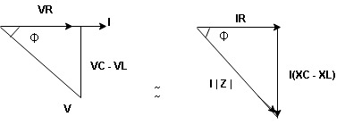
Now V = VR + VL + VC  phases sum and VL and VC are directly in phase opposition and VC
 VL
VL  their resultant is (VC – VL)
From voltage 
V = 
V = 
 V =
V = 
 V =
V = 

 Impedance
  : Divide voltage
- Rectangular form : Z + R – j (XC – XL) – 4th qurd
Polar form : Z =  L -
L -
Where 
And Ø = tan-1 – 
- Voltage equation : V = Vm Sin wt
- Current equation : i =
 from B
 - i =
 L+Ø C
L+Ø C
As VC  the circuit is mostly capacitive and
  leads voltage by angle Ø
Since i =  L + Ø
L + Ø
 Sin (wt – Ø) from C
- Power
 :
:
- XL= XC (resonance condition):
ɡȴ XL= XC then VL= VC and they are 1800 out of phase with each other  they will cancel out each other and their resultant will have zero value.
Hence resultant V = VR and it will be in phase with I as shown in the below phasor diagram.
From the above resultant phasor diagram
V =VR + IR
Or V = I  lZl
lZl
Because lZl + R
Thus Impedance Z is purely resistive for XL = XC and circuit current will be in phase with source voltage.

 Since VR=V Øis zero when XL = XC
  power is unity
Ie pang = Vrms I rms cos Ø = 1 cos o = 1
Maximum power will be transferred by the condition. XL = XC
4. Explain bandwidth of series resonance circuit ?
Then the relationship between resonance, bandwidth, selectivity and quality factor for a series resonance circuit being defined as:
1). Resonant Frequency, (ƒr)
XL = Xc
WrL -1/wrC =0
Wr2 = 1/LC ;
Wr = 1/ 
2). Current, (I)
At wr ZT =min Is = max
I max = Vmax/Z = Vmax/ [ R2 + (XL-Xc) 2 ] = Vmax / [ R2 +( wr L – 1/wrC )] ½
3). Lower cut-off frequency, (ƒL)
At half power , Pm/2 , I = Im/2 = 0.7071 Im
Z =  R , X = -R (capacitive)
wL = -R/2L + [ (R/2L) 2 + 1/LC] ½
4). Upper cut-off frequency, (ƒH)
At half power Pm/2 , I = Im /  = 0.7071 Im
Z =  R , X = +R (inductive)
wH = + R/2L + [ (R/2L) 2 + 1/LC] ½
5). Bandwidth, (BW)
BW = fr/Q ; fH – fL ; R/L rads or R/2 πL (Hz)
6). Quality Factor, (Q)
Q = wL/R = XL/R = 1/ wr CR = Xc/R = 1/R . [L/C] ½
5. What is quality factor ?
Quality factor, Q of the circuit. The quality factor relates the maximum or peak energy stored in the circuit (the reactance) to the energy dissipated (the resistance) during each cycle of oscillation meaning that it is a ratio of resonant frequency to bandwidth and the higher the circuit Q, the smaller the bandwidth,
Q = ƒr /BW.
6. Explain R-L-C parallel circuit?
In the above parallel RLC circuit, the supply voltage, VS is common to all three components whilst the supply current IS consists of three parts. The current flowing through the resistor, IR, the current flowing through the inductor, IL and the current through the capacitor, IC.
The phasor diagram for a parallel RLC circuit is produced by combining together the three individual phasors for each component and adding the currents vectorially.
Since the voltage across the circuit is common to all three circuit elements we can use this as the reference vector with the three current vectors drawn relative to this at their corresponding angles.
The resulting vector current IS is obtained by adding together two of the vectors, IL and IC and then adding this sum to the remaining vector IR.
The resulting angle obtained between V and IS will be the circuits phase angle as shown below.
Phasor Diagram for a Parallel RLC Circuit
From the phasor diagram on the right hand side above that the current vectors produce a rectangular triangle, comprising of hypotenuse IS, horizontal axis IR and vertical axis IL – IC .
IS 2 = IR 2 + (IL – IC) 2
IS =[ IR 2 + (IL – IC) 2] ½
IS =[(V/R) 2 + (V/XL – V/XC) 2] ½ = V/Z
Since the voltage across the circuit is common to all three circuit elements, the current through each branch can be found using Kirchhoff’s Current Law, (KCL). Thus, the currents entering and leaving node “A” above are given as:
IS - IR -IL – IC = 0
IS – V/R – 1/L  dt – C dv/dt =0
Taking the derivative, dividing through the above equation by C and then re-arranging gives us the following Second-order equation for the circuit current.
It becomes a second-order equation because there are two reactive elements in the circuit, the inductor and the capacitor.
IS –d2 V/dt2 – dV/RC .dt – V/LC =0
IS (t) = d2V/dt 2 + dV/dt . 1/RC + 1/LC .V
The opposition to current flow in this type of AC circuit is made up of three components: XL XC and R with the combination of these three values giving the circuits impedance, Z.
7. Explain impedance of parallel RLC circuit?
R = V/IR XL = V/IL XC = V/IC
Z = 1/  ) 2 + (1/XL – 1/Xc) 2
Z =[ (1/R) 2 + (1/XL – 1/Xc) 2 ] ½
8.A 50Ω resistor, a 20mH coil and a 5uF capacitor are all connected in parallel across a 50V, 100Hz supply. Calculate the total current drawn from the supply, the current for each branch, the total impedance of the circuit and the phase angle. Also construct the current and admittance triangles representing the circuit.
1). Inductive Reactance, ( XL ):
XL = wL = 2πfL = 2π . 100. 0.02 = 12.6 Ω
2). Capacitive Reactance, ( XC ):
Xc = 1/wC = 1/ 2πfC = 1/ / 2πx 100.5 x 10 -6 = 318.3 Ω
3). Impedance, ( Z ):
Z = 1/  (1/R) 2 + (1/Xc – 1/XL) 2 = 1/
  (1/50) 2 + ( 1/318.3 – 1/12.6)2
Z = 1/0.0788 = 12.7 Ω
4). Current through resistance, R ( IR ):
IR = V/R = 50/50 = 1A
5). Current through inductor, L ( IL ):
IL = V/XL = 50/12.6 = 3.9 A
6). Current through capacitor, C ( IC ):
IC = V/Xc = 50/ 318.3 = 0.16 (A)
7). Total supply current, ( IS ):
Is = [ IR 2 + (IL – IC) 2 ] ½ = [ 1 2 + (3.9 – 0.16) 2 ] ½ = 3.87 A
8). Conductance, ( G ):
G = 1/R = 1/50 = 20ms
9). Inductive Susceptance, ( BL ):
BL = 1/XL = 1/12.6 = 80ms
12). Phase Angle, ( φ ) between the resultant current and the supply voltage:
Cos ɸ = G/Y = 20ms/78ms = 0.256
ɸ = cos -1 0.256 = 75.3 (lag)
9.Explain bandwidth?
The bandwidth of a parallel resonance circuit is defined in exactly the same way as for the series resonance circuit. The upper and lower cut-off frequencies given as: ƒupper and ƒlower respectively denote the half-power frequencies where the power dissipated in the circuit is half of the full power dissipated at the resonant frequency 0.5( I2 R ) which gives us the same -3dB points at a current value that is equal to 70.7% of its maximum resonant value, ( 0.707 x I )2 R
BW = ƒr /Q or BW = ƒupper - ƒlower
10. Explain Q-factor?
Q-factor for a parallel resonance circuit is generally defined as the ratio of the circulating branch currents to the supply current and is given as:
Quality factor Q = R/ 2π fL = 2π f C R = R  C/L
C/L
11. Explain the solution to series and parallel circuits ?
Consider the following circuit
We can represent as

R1 and R2 are connected in a simple parallel arrangement, as are R3 and R4.
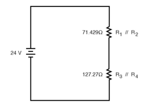

The final step in reduction is to add these two resistances to come up with a total circuit resistance. When we add those two equivalent resistances, we get a resistance of 198.70 Ω.
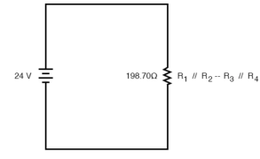

Now, total circuit current can be determined by applying Ohms law (I=E/R) to the “Total” column in the table:

The total current value of 120.78 milliamps is shown as the only current here:
Knowing the current through the equivalent resistors R1//R2 and R3//R4, we can apply Ohm’s Law (E=IR) to the two right vertical columns to find voltage drops across them:
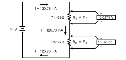

For the previous circuit

Applying Ohm’s Law to the remaining vertical columns (I=E/R), we can determine the currents through R1, R2, R3, and R4 individually:

Therefore,
12.A voltage in a circuit has the form
V(t) = 10 cos (2t-45) V
Find the corresponding phasor in polar and rectangular form.
Solution :
 = 10 cos (-45) + j 10 sin(-45)
= 10 cos 45 – j10 sin(45)
= 10 /  – j 10 /
= 5  - j 5
- j 5  V
V
13. Explain admittance method ?
Admittance is defined as the effective ability of the circuit due to which it allows the alternating current to flow through it. It is represented by (Y). The old unit of admittance is mho (Ʊ). Its new unit is Siemens.
Step 1 – Draw the circuit as per the given problem.
Step 2 – Find the impedance and phase angle of each branch.
Z1 = [ R1 2 + X2 c1] ½ ɸ1 = tan-1 Xc1/R1
Z2 = [ R2 2 + X2 L2] ½ ɸ2 = tan-1 XL2/R2
Step 3 – Now, find Conductance, Susceptance and Admittance of each branch.
g 1 = R1 / Z1 2 ; b1 = Xc1/ Z1 2 (positive) ; Y1 = [ g1 2 + b1 2] ½
g2 = R2 / Z2 2 ; b2 = XL2/Z2 2 (negative ) ; Y2 = [ g2 2 + b2 2] ½
Step 4 – Find the algebraic sum of conductance and susceptance.
G = g1 + g2 ; B = b1 – b2
Step 5 – Find the total Admittance (Y) of the circuit.
Y = [ G2 + B2 ] ½
Step 6 – Find the various branch currents of the circuit.
I1 = VY1 and I2 = V Y2
Step 7 – Now, find the total current I of the circuit.
I = V Y
Step 8 – Find the phase angle of the whole circuit.
ɸ = tan -1 B/G
Phase angle will be lagging if B is negative.
Step 9 – Now, find the power factor of the circuit.
Power factor = cos ɸ = G/Y
14. Explain complex algebra method ?
Complex numbers are used in AC circuits because resistors , capacitors and inductors (L) all react differently to AC current. The effective resistance of each element is called reactance.

Each element reacts differently to current. Thus, the AC voltage through each element either lags or leads the current.
Consider the following circuit :
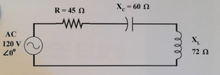
Z = [ 12 2 + 45 2 ]
Ɵ= tan -1 (12/45) = 15 0
Z = 46.57 < 15 0