UNIT –5
Analysis of Plane Trusses
Question 1) Determine the forces in all members of truss by joint method
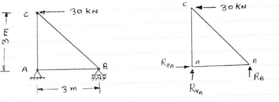
Answer 1) Consider FAB of Truss, Applying conditions of equilibrium,
 = 0
= 0
RHA + 30 Kn
 = 0
= 0
RvA + RB =0
Taking moment at point A, = 0
= 0
-(RB* 3) - (30*3) = 0
RB = -30 KN
RB =30 KN RVA = 30 KN
Consider Joint c, Assuming forces in member AC & BC to be
Tensile, Applying conditions of equilibrium, 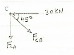
 = 0
= 0
-30 + FCB cos 45 =0
FCB =30/cos 45 = 42.42 KN (T)
-  = 0
= 0
- FcA – FCB sin 45=o
- F cA -42.42 sin 45 =0 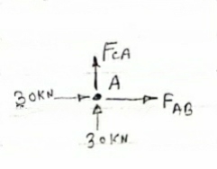
-FCA – 30= 0
-FCA = -30 KN
Consider Joint c, Assuming forces in member AC & BC to be
Tensile, Applying conditions of equilibrium,
 Fx = 0 30+FAB =0
FAB = -30KN
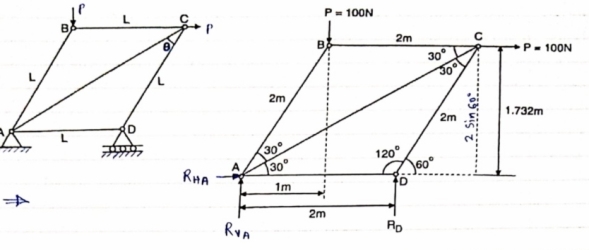
Question 2) Determine the forces in each member of the plane truss as shown in fig. In terms pf the external loading and state if the members are in tension or compression. Use 0+ 30 deg, L = 2 m and p =100N.
Diagram
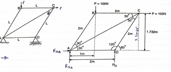
Answer 2) Consider FBD of Truss,
For equilibrium,  Fx =0
Fx =0
RHA+100 =0
RHA =-100 KN
 Fy =0 RVA = RD – 100 ….. 1
MA = 0 -------Taking moment @ A
- (Roxz) + (100*1) + (100*1.732) =0
- - 2 Rd + 100 + 1.7320 =0
- -2 Rd + 100 + 173.2 =0
- RD =136.66 N ()
From eqn (1)
RVA = 100 – 136.6
RVA= 36.6N
RVA = 36.6 N
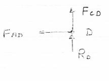
Consider Joint D, for equilibrium,
Fx =0
-FAD + FCD cos 60 =0 – (11)
Fy = 0
136.6 +FCD sin 60 +0 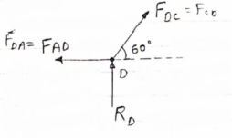
FCD = -157.73 N ©
From eqn (11), Fad =- 78. 87 N (c)
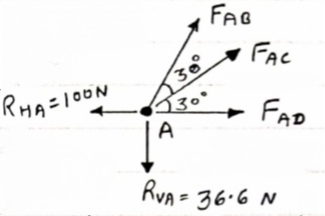
Consider point A, for the equilibrium of point A,
 Fx = 0
- 100 + FAD + FAc cos + 30 FAb cos60 = 0
-100 + (-78.87) +FAC cos 30 +FAb cos60 =0
FAc cos 30 + FAB cos60 + 178. 87 (3)
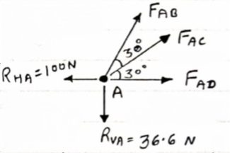
 fx =0
fx =0
-36.6 + FAC sin 30 + FAB sin 60 =0
FAC sin 30 + FAb sin 60 = 36.6
Solving eqn (3) and (4)
FAC = 273.21 N (T)
FAB = -115.47 N
FAB= 115.47 N ©
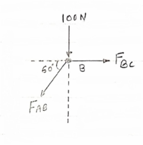
Consider point B, for the equilibrium of point,
 Fx =0
Fx =0
-FAB cos60 + FBC =0
-[9-115.47) cos60]+ FBC =0
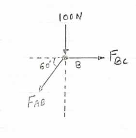
FBC = -57.73 N
FBC =57.73N
Member | AB | BC | CD | AD | AC |
Force | 115.47N | 57.73N | 157.73N | 78.87N | 273.21N |
Nature | c | c | c | c | T |
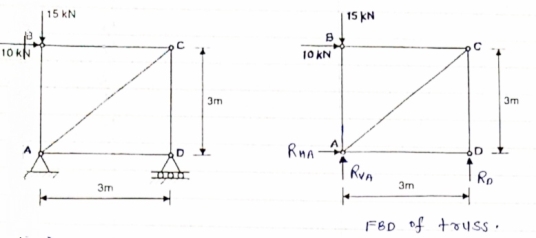
Question 3) Determine the axial forces in each member of the plane truss as shown in figure.
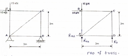
Answer 3) consider FBD of Truss,
For the equilibrium of Truss,  fx =0
fx =0
RHA + 10 =0
RHA = -10 KN
RHA =10KN (
Resolving forces vertically,
 fy =o
fy =o
RVA + RD -15 =0
RVA + RD = 15 …… (1)
Taking moment about point A,
 Fy =0
Fy =0
(10*3) – 3 Rd =0
30+ 3 Rd =0
RD= 10 KN 
RVA = 5KN ( )
)
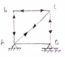
Now Consider joint B, FBD of joint B is shown below.
Assuming forces developed in all members to be Termile,
For the equilibrium of joint We have
 fx =0
fx =0
10+FBC =0 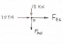
FBC = -10 KN
FBC = 10KN (c)
 fy =0
fy =0
FAB = -15 KN
FAB = 15 KN (c)
Now consider joint c,
For the equilibrium of joint,
 fx =0
fx =0
-FBC – FAC cos 45 =0
- (-10) – FAC cos 45=0
10= FAC cos 45
FAC = 10/cos 45 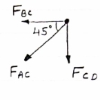
FAc = 14.14 KN (T)
 fy =0
fy =0
-Fac sin 45 – FCD=0
- 14.14 sin45 = FCD
FCD = -10 KN (c)
FCD= 10 KN (c)
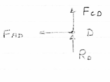
Consider joint D,
By observation,
FAD=0
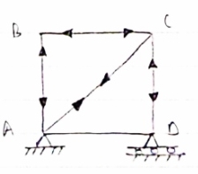
Sr .No | Member | Force | Nature |
1 | AB | 15 KN | c |
2 | BC | 10KN | c |
3 | CD | 10KN | c |
4 | DA | 0 | - |
5 | AC | 14.14 | T |
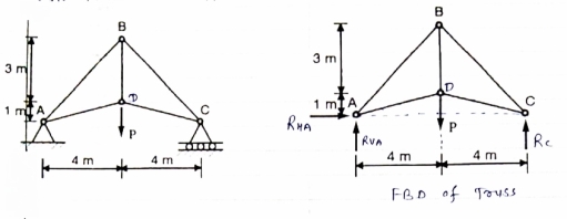
Question 4) Member AB & BC can support a maximum compressive force of 800 N & members AD, DC, BD can support a max. Tensile. Force of 2000N Determine the greatest land p that
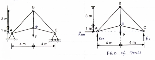
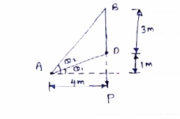
Answer 4) Consider following geometry of the figure.
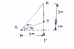
Tan 1 = ¼
1 = ¼
 14.04
14.04
 2 =
2 =  =45
=45
 Consider
 fx =0 RHA = 0
∈Fy =o RVA + Rc = p………(1)
∈ma =0
Hp- 8 Rc =0
Rc =P/2 N ( ) RvA = (P/2) N (
 )
)
Consider point A C assuming all forces as Tensile)
∈fx =0
FAD cos 14.04+FAB cos 45 =0… (2)
∈fy = 0 p/2= Fad sin 14.04 + FAB sin 45 =0….. (3)
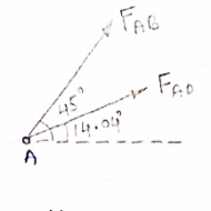
FAB = 2743.9 N > 800 N ( Not Allowed)
Let FAD = 2000 N (T) Then from eqn (2) & (3)
FAB =-274.9 N > 800 ( Not allowed)
Let FAB = .800 N ©, Then put this eqn (2) (3) we get
FAB = 583 N < 2000 N (Allowed) From Eqn (2) P= 848.9 N
Question 5) Determine the forces in members 8E and BD of the truss which supports the load as shown in figure.
Answer 5) All interior angle are 60 &120
 Consider joint G
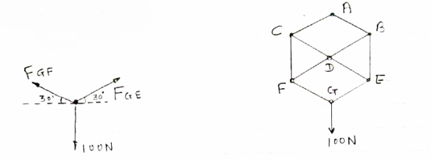
∈fx= 0 FGE cos 30- FGF cos 30= 0
FGE cos30= FGF cos 30
FGE=FGF
∈fy=0 FGE sin 30 +FGF sin 30 – 100 =0
FGE sin 30 + FGE sin 30- 100 =0
FGE = 100 N (T)
Consider joiny E
∈ Fx =0
-FDE cos 30 – FGE cos 30 =0
-FDE cos 30 – 100 cos 30=0 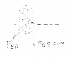
FDE = -100 N
FDE = 100 N (c)
∈Fy =0
FGE sin 30 + FBE -100 sin 30 =0
(-100) sin 30 = FBE – 100 sin 30
FBE = 100 N (T)
Consider Joint B
 fx = 0 :. – FAB cos30 – FBD cos30 =0
:. – FAB –FBD = 0 ……(1) 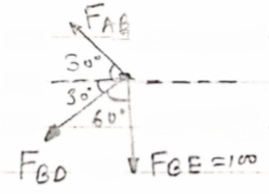
 fy = 0
FAB sin30- FBD sin 30b - FBE = 0
FAB sin30- FBD sin 30=100
(FAB – FBD)= 200 …………(II)
Solving (1) &(II) FAB = 100N (T) FBD = 100N
Question 6) Determine the force in each member of the truss as Shown in fig & tabulate the result with magnitude & nature of force in the members.
Diagram
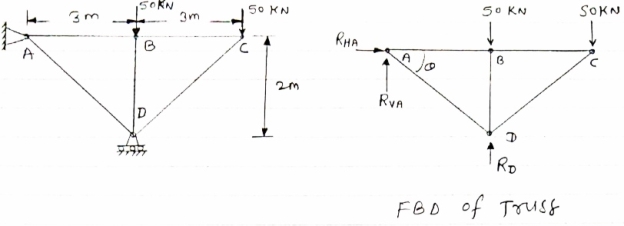
Answer 6) Consider FBD of Truss,
For equilibrium,∈fx =0
RHA=0
∈fy =0Zn  ABD
ABD
RVA-50-50+RD =0tan =2/3
=2/3
RVA + RD =100 = 33.7
Taking moment @ point A,
∈MA =0
-(RD*3) = (50*3) +(50*6) =0
-3Rd = 150 +300 =0
-3Rd = -450
RD = 150 KN (  )
)
RVA= RD = 100
RVA = 150 = 100
RVA= -50
RVA= 50 KN(  )
)
Consider joint A,
Diagram 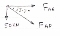
 fx =0,
FAB + FAD cos 33.7 =0
 fy =0
fy =0
-50- FAD sin 33.7 =0
FAD = 50/-sin 33.7FAD = - 90.1 KN (c)
FAB + (-90.1) cos 33.7 =0FAB = 74.96 KN (T
Consider joint B
 fx =0
fx =0
-FAB + FBC =0
Diagram 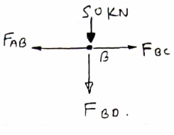
FBC = 74.96 Kn (T)
 fy =0
fy =0
-50-FBD =0
FBD = -50Kn
FBD= 50 Kn
Consider joint c :-
 fx =0
fx =0
-FBC- FDC cos 33.7 =0
Diagram
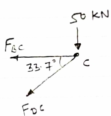
-74.96-FDC cos 33.7 =0
FDC cos 33.7 = -74.96
FDC cos 33.7 = -74.96
DDC = -90.11 KN
FDC = 90.11 KN (c)
Sr No | Member | Force | Nature |
1 | AB | 74.96KN | T |
2 | BC | 74.96KN | T |
3 | CD | 90.11 KN | C |
4 | AD | 90.11 KN | C |
5 | BD | 50KN | C |
Question 7) For Given truss find forces in the members BC, AC and AE
Diagram
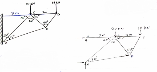 Cantilever Truss
Answer 7) for cantilever Truss, Reaction can be calculated only after the calculated only after the calculation of forces in each members.
Consider joint D, for Equilibrium of joint,
 fx=0
fx=0
-Fcd- FDE cos60 = 0 ……. (1)
Diagram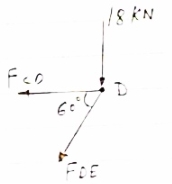
 fy =0
fy =0
-18- FDE sin60 = 0
-FDE sin60 = 18
FDE = -20.78 KN
FDE = 20.78 KN
From eqn (1)
-FCD –(-20.78) cos 60 =0
FCD = 20.78 KN
From eqn (1)
-FCD – (20.78)cos 60 =0
FCD = 10.39KN (T)
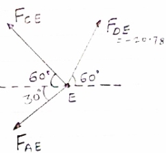
Consider joint E, for equilibrium of joint,
 fx =0
fx =0
-FCE cos 60- FAE cos30+FDE cos 60 =0
-0.5 FCE -0.866 FAE cos 30 +(-20.78*0.5)=0
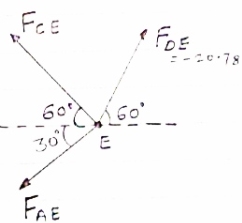
-0.5 FCE-0.866 FAE = 10.39 …..(3)
 Fy =0
Fy =0
(-20.78 sin 60) + FCE sin60- FAE sin 30= 0
0.866 FCE – 0.5 FAE = 17.99 (3)
Solving eqn (2) & (3) FCE= 10.38 KN (T) FAE = -17.99 KN = 17.99 KN (c)
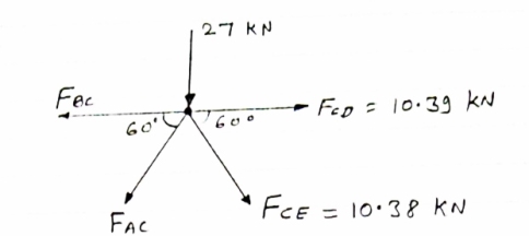
Consider joint C, Equilibrium of the joint
Diagram
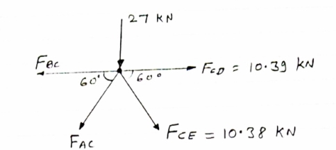
Efx = 0
 - FBC + FCD + FCEcos 60 – FACcos 60 = 0
- FBC + 10.39 + 10.38 cos 60 – FACcos 60 = 0
 - FBC + FACcos 60 = -15.58 ………iv
∑fy = 0
-27 - FAC sin 60 - FCE sin 60 = 0
-27 - FAC sin 60 – 10.38 sin 60 = 0
- FAC sin 60 = 35.99
 - FAC = 41.56 kn
FAC = 41.56 KN
From eqnIV
-FBC – (-41.56cos 60) = -15.58
-FBC = -15.58 – 20.78
-FBC = -36.36 KN
 - FBC = 36.l36 KN …. (T)
Member | BC | AC | AE |
Force | 36.36 KN | 41.56 KN | 17.99 KN |
Nature | T | C | C |
Question 8) Determine the force in the members of the truss loaded supported as shown the fig. Tabulate the result with magnitude and nature of force the members.
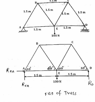
Answer 8) Consider the FBD of truss as show below
For equilibrium of truss
EFx = 0
 RHA = 0
Taking moment @ A
∑MA = 0
 (100
(100  1.5) – (3
  D) = 0
 D = 0
D = 0
 D = 150
 D = 50 N
∑Fy = 0
 RVA
RVA D – 100 = 0
 RVA
RVA – 100 = 0
RVA = 50 N
Consider joint A,
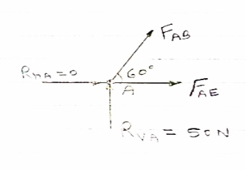
For equilibrium of joint
∑FX = 0
 FABCos60
  AE = 0 ……..①
∑Fy = 0
 RVA
RVA ABSin 60 = 0
 ABSin 60 = 0
FAB = 
FAB = 57.73 N
FAB = 57.73 N ©
From eqn ①
-057.73 Cos 60 + FAE = 0
FAE = 28.86 N (T)
Consider joint B, for the equilibrium of joint
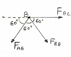
∑FX = 0
 FBC + FBECos60
  ABCos 60 = 0
 FBC + FBECos60
  = 0
= 0
 FBC + FBECos60 = 28.86 ②
∑FY = 0
- FAB Sin 60 – FBE Sin 60
-(-57.73 Sin 60) = FBE Sin 60
57.73 Sin 60 = FBE Sin 60
FBE = 57.73 N (T)
From eqn ②
FBC + 57.73 Cos 60 = - 28.86
FBC + 28.86 = - 28.86
FBC = - 57.73 N
FBC = 57.73 N
Consider joint C, for equilibrium of joint
∑FX = 0
 - 57.73 – FCE Cos 60 + FCD Cos 60 = 0
FCE Cos 60 + FCD Cos 60 = 57.73 ……③
∑FY = 0
FCE Sin 60 - FCD Sin 60 = 0 …….④
Solving eqn ③ and④
 FCE = - 57.73 N
 FCE = - 57.73 N and FCD = - 57.73 N (T)
Consider joint D, for equilibrium of joint
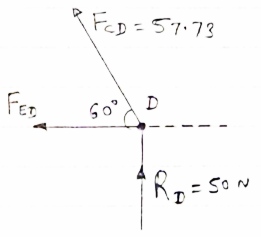
∑FX = 0
 - FED – FCD Cos 60 = 0
 - FED – 57.73 Cos 60 = 0
- FED = -28.86 N
FED = -28.86 N (T)
Member | AB | BC | CD | DE | AE | BE | CE |
Force | 57.73 N | 57.73 N | 57.73 N | 28.86 N | 28.86 N | 57.73 N | 57.73 N |
Nature | C | C | T | T | T | T | C |
Question 9) Explain truss?
Answer 9) Truss:-
A Rigid structure formed by connecting various two force members to each other by using pin joint..
Plane truss: When all member of the truss lies in one plane, Then truss is known as plane truss
Rigid truss:- A truss which do not collapse when external Load is applied on it.
Simple truss:-The structure formed by basic triangle made by Connecting various members are called simple truss.
Question 10) Explain method of section?
Answer 10) Method of section: This method entails passing an imaginary section through the truss to divide it into two sections. The member forces are determined by considering the equilibrium of the part of the truss on either side of the section. This method is advantageous when the axial forces in specific members are required in a truss with several members.

Analysis of Trusses by Method of Section
Sometimes, determining the axial force in specific members of a truss system by the method of joint can be very involving and cumbersome, especially when the system consists of several members. In such instances, using the method of section can be timesaving and, thus, preferable. This method involves passing an imaginary section through the truss so that it divides the system into two parts and cuts through members whose axial forces are desired. Member axial forces are then determined using the conditions of equilibrium. The detailed procedure for analysis by this method is presented below.
Procedure for Analysis of Trusses by Method of Section
•Check the stability and determinacy of the structure. If the truss is stable and determinate, then proceed to the next step.
•Determine the support reactions in the truss.
•Make an imaginary cut through the structure so that it includes the members whose axial forces are desired. The imaginary cut divides the truss into two parts.
•Apply forces to each part of the truss to keep it in equilibrium.
•Select either part of the truss for the determination of member forces.
•Apply the conditions of equilibrium to determine the member axial forces.
UNIT –5
UNIT –5
UNIT –5
Analysis of Plane Trusses
Question 1) Determine the forces in all members of truss by joint method
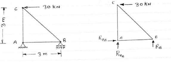
Answer 1) Consider FAB of Truss, Applying conditions of equilibrium,
 = 0
= 0
RHA + 30 Kn
 = 0
= 0
RvA + RB =0
Taking moment at point A, = 0
= 0
-(RB* 3) - (30*3) = 0
RB = -30 KN
RB =30 KN RVA = 30 KN
Consider Joint c, Assuming forces in member AC & BC to be
Tensile, Applying conditions of equilibrium, 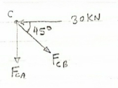
 = 0
= 0
-30 + FCB cos 45 =0
FCB =30/cos 45 = 42.42 KN (T)
-  = 0
= 0
- FcA – FCB sin 45=o
- F cA -42.42 sin 45 =0 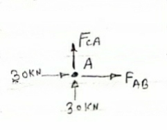
-FCA – 30= 0
-FCA = -30 KN
Consider Joint c, Assuming forces in member AC & BC to be
Tensile, Applying conditions of equilibrium,
 Fx = 0 30+FAB =0
FAB = -30KN
Question 2) Determine the forces in each member of the plane truss as shown in fig. In terms pf the external loading and state if the members are in tension or compression. Use 0+ 30 deg, L = 2 m and p =100N.
Diagram
Answer 2) Consider FBD of Truss,
For equilibrium,  Fx =0
Fx =0
RHA+100 =0
RHA =-100 KN
 Fy =0 RVA = RD – 100 ….. 1
MA = 0 -------Taking moment @ A
- (Roxz) + (100*1) + (100*1.732) =0
- - 2 Rd + 100 + 1.7320 =0
- -2 Rd + 100 + 173.2 =0
- RD =136.66 N ()
From eqn (1)
RVA = 100 – 136.6
RVA= 36.6N
RVA = 36.6 N
Consider Joint D, for equilibrium,
Fx =0
-FAD + FCD cos 60 =0 – (11)
Fy = 0
136.6 +FCD sin 60 +0 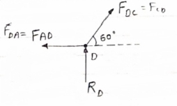
FCD = -157.73 N ©
From eqn (11), Fad =- 78. 87 N (c)
Consider point A, for the equilibrium of point A,
 Fx = 0
- 100 + FAD + FAc cos + 30 FAb cos60 = 0
-100 + (-78.87) +FAC cos 30 +FAb cos60 =0
FAc cos 30 + FAB cos60 + 178. 87 (3)
 fx =0
fx =0
-36.6 + FAC sin 30 + FAB sin 60 =0
FAC sin 30 + FAb sin 60 = 36.6
Solving eqn (3) and (4)
FAC = 273.21 N (T)
FAB = -115.47 N
FAB= 115.47 N ©
Consider point B, for the equilibrium of point,
 Fx =0
Fx =0
-FAB cos60 + FBC =0
-[9-115.47) cos60]+ FBC =0
FBC = -57.73 N
FBC =57.73N
Member | AB | BC | CD | AD | AC |
Force | 115.47N | 57.73N | 157.73N | 78.87N | 273.21N |
Nature | c | c | c | c | T |
Question 3) Determine the axial forces in each member of the plane truss as shown in figure.
Answer 3) consider FBD of Truss,
For the equilibrium of Truss,  fx =0
fx =0
RHA + 10 =0
RHA = -10 KN
RHA =10KN (
Resolving forces vertically,
 fy =o
fy =o
RVA + RD -15 =0
RVA + RD = 15 …… (1)
Taking moment about point A,
 Fy =0
Fy =0
(10*3) – 3 Rd =0
30+ 3 Rd =0
RD= 10 KN 
RVA = 5KN ( )
)
Now Consider joint B, FBD of joint B is shown below.
Assuming forces developed in all members to be Termile,
For the equilibrium of joint We have
 fx =0
fx =0
10+FBC =0 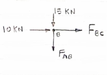
FBC = -10 KN
FBC = 10KN (c)
 fy =0
fy =0
FAB = -15 KN
FAB = 15 KN (c)
Now consider joint c,
For the equilibrium of joint,
 fx =0
fx =0
-FBC – FAC cos 45 =0
- (-10) – FAC cos 45=0
10= FAC cos 45
FAC = 10/cos 45 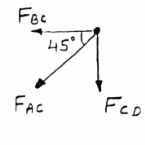
FAc = 14.14 KN (T)
 fy =0
fy =0
-Fac sin 45 – FCD=0
- 14.14 sin45 = FCD
FCD = -10 KN (c)
FCD= 10 KN (c)
Consider joint D,
By observation,
FAD=0
Sr .No | Member | Force | Nature |
1 | AB | 15 KN | c |
2 | BC | 10KN | c |
3 | CD | 10KN | c |
4 | DA | 0 | - |
5 | AC | 14.14 | T |
Question 4) Member AB & BC can support a maximum compressive force of 800 N & members AD, DC, BD can support a max. Tensile. Force of 2000N Determine the greatest land p that
Answer 4) Consider following geometry of the figure.
Tan 1 = ¼
1 = ¼
 14.04
14.04
 2 =
2 =  =45
=45
 Consider
 fx =0 RHA = 0
∈Fy =o RVA + Rc = p………(1)
∈ma =0
Hp- 8 Rc =0
Rc =P/2 N ( ) RvA = (P/2) N (
 )
)
Consider point A C assuming all forces as Tensile)
∈fx =0
FAD cos 14.04+FAB cos 45 =0… (2)
∈fy = 0 p/2= Fad sin 14.04 + FAB sin 45 =0….. (3)
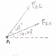
FAB = 2743.9 N > 800 N ( Not Allowed)
Let FAD = 2000 N (T) Then from eqn (2) & (3)
FAB =-274.9 N > 800 ( Not allowed)
Let FAB = .800 N ©, Then put this eqn (2) (3) we get
FAB = 583 N < 2000 N (Allowed) From Eqn (2) P= 848.9 N
Question 5) Determine the forces in members 8E and BD of the truss which supports the load as shown in figure.
Answer 5) All interior angle are 60 &120
 Consider joint G
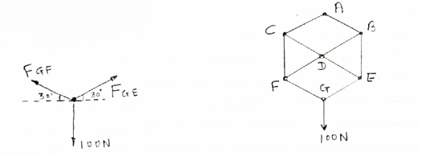
∈fx= 0 FGE cos 30- FGF cos 30= 0
FGE cos30= FGF cos 30
FGE=FGF
∈fy=0 FGE sin 30 +FGF sin 30 – 100 =0
FGE sin 30 + FGE sin 30- 100 =0
FGE = 100 N (T)
Consider joiny E
∈ Fx =0
-FDE cos 30 – FGE cos 30 =0
-FDE cos 30 – 100 cos 30=0 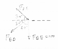
FDE = -100 N
FDE = 100 N (c)
∈Fy =0
FGE sin 30 + FBE -100 sin 30 =0
(-100) sin 30 = FBE – 100 sin 30
FBE = 100 N (T)
Consider Joint B
 fx = 0 :. – FAB cos30 – FBD cos30 =0
:. – FAB –FBD = 0 ……(1) 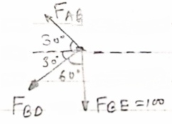
 fy = 0
FAB sin30- FBD sin 30b - FBE = 0
FAB sin30- FBD sin 30=100
(FAB – FBD)= 200 …………(II)
Solving (1) &(II) FAB = 100N (T) FBD = 100N
Question 6) Determine the force in each member of the truss as Shown in fig & tabulate the result with magnitude & nature of force in the members.
Diagram
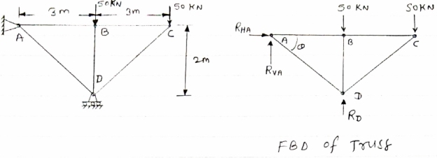
Answer 6) Consider FBD of Truss,
For equilibrium,∈fx =0
RHA=0
∈fy =0Zn  ABD
ABD
RVA-50-50+RD =0tan =2/3
=2/3
RVA + RD =100 = 33.7
Taking moment @ point A,
∈MA =0
-(RD*3) = (50*3) +(50*6) =0
-3Rd = 150 +300 =0
-3Rd = -450
RD = 150 KN (  )
)
RVA= RD = 100
RVA = 150 = 100
RVA= -50
RVA= 50 KN(  )
)
Consider joint A,
Diagram 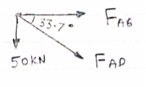
 fx =0,
FAB + FAD cos 33.7 =0
 fy =0
fy =0
-50- FAD sin 33.7 =0
FAD = 50/-sin 33.7FAD = - 90.1 KN (c)
FAB + (-90.1) cos 33.7 =0FAB = 74.96 KN (T
Consider joint B
 fx =0
fx =0
-FAB + FBC =0
Diagram 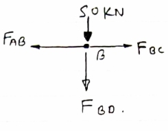
FBC = 74.96 Kn (T)
 fy =0
fy =0
-50-FBD =0
FBD = -50Kn
FBD= 50 Kn
Consider joint c :-
 fx =0
fx =0
-FBC- FDC cos 33.7 =0
Diagram
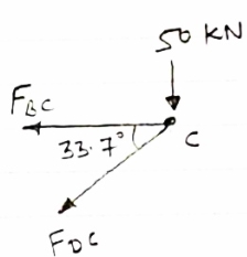
-74.96-FDC cos 33.7 =0
FDC cos 33.7 = -74.96
FDC cos 33.7 = -74.96
DDC = -90.11 KN
FDC = 90.11 KN (c)
Sr No | Member | Force | Nature |
1 | AB | 74.96KN | T |
2 | BC | 74.96KN | T |
3 | CD | 90.11 KN | C |
4 | AD | 90.11 KN | C |
5 | BD | 50KN | C |
Question 7) For Given truss find forces in the members BC, AC and AE
Diagram
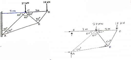 Cantilever Truss
Answer 7) for cantilever Truss, Reaction can be calculated only after the calculated only after the calculation of forces in each members.
Consider joint D, for Equilibrium of joint,
 fx=0
fx=0
-Fcd- FDE cos60 = 0 ……. (1)
Diagram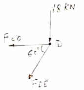
 fy =0
fy =0
-18- FDE sin60 = 0
-FDE sin60 = 18
FDE = -20.78 KN
FDE = 20.78 KN
From eqn (1)
-FCD –(-20.78) cos 60 =0
FCD = 20.78 KN
From eqn (1)
-FCD – (20.78)cos 60 =0
FCD = 10.39KN (T)
Consider joint E, for equilibrium of joint,
 fx =0
fx =0
-FCE cos 60- FAE cos30+FDE cos 60 =0
-0.5 FCE -0.866 FAE cos 30 +(-20.78*0.5)=0
-0.5 FCE-0.866 FAE = 10.39 …..(3)
 Fy =0
Fy =0
(-20.78 sin 60) + FCE sin60- FAE sin 30= 0
0.866 FCE – 0.5 FAE = 17.99 (3)
Solving eqn (2) & (3) FCE= 10.38 KN (T) FAE = -17.99 KN = 17.99 KN (c)
Consider joint C, Equilibrium of the joint
Diagram
Efx = 0
 - FBC + FCD + FCEcos 60 – FACcos 60 = 0
- FBC + 10.39 + 10.38 cos 60 – FACcos 60 = 0
 - FBC + FACcos 60 = -15.58 ………iv
∑fy = 0
-27 - FAC sin 60 - FCE sin 60 = 0
-27 - FAC sin 60 – 10.38 sin 60 = 0
- FAC sin 60 = 35.99
 - FAC = 41.56 kn
FAC = 41.56 KN
From eqnIV
-FBC – (-41.56cos 60) = -15.58
-FBC = -15.58 – 20.78
-FBC = -36.36 KN
 - FBC = 36.l36 KN …. (T)
Member | BC | AC | AE |
Force | 36.36 KN | 41.56 KN | 17.99 KN |
Nature | T | C | C |
Question 8) Determine the force in the members of the truss loaded supported as shown the fig. Tabulate the result with magnitude and nature of force the members.
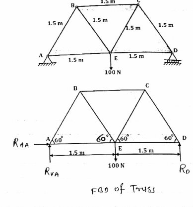
Answer 8) Consider the FBD of truss as show below
For equilibrium of truss
EFx = 0
 RHA = 0
Taking moment @ A
∑MA = 0
 (100
(100  1.5) – (3
  D) = 0
 D = 0
D = 0
 D = 150
 D = 50 N
∑Fy = 0
 RVA
RVA D – 100 = 0
 RVA
RVA – 100 = 0
RVA = 50 N
Consider joint A,
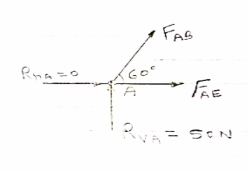
For equilibrium of joint
∑FX = 0
 FABCos60
  AE = 0 ……..①
∑Fy = 0
 RVA
RVA ABSin 60 = 0
 ABSin 60 = 0
FAB = 
FAB = 57.73 N
FAB = 57.73 N ©
From eqn ①
-057.73 Cos 60 + FAE = 0
FAE = 28.86 N (T)
Consider joint B, for the equilibrium of joint
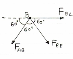
∑FX = 0
 FBC + FBECos60
  ABCos 60 = 0
 FBC + FBECos60
  = 0
= 0
 FBC + FBECos60 = 28.86 ②
∑FY = 0
- FAB Sin 60 – FBE Sin 60
-(-57.73 Sin 60) = FBE Sin 60
57.73 Sin 60 = FBE Sin 60
FBE = 57.73 N (T)
From eqn ②
FBC + 57.73 Cos 60 = - 28.86
FBC + 28.86 = - 28.86
FBC = - 57.73 N
FBC = 57.73 N
Consider joint C, for equilibrium of joint
∑FX = 0
 - 57.73 – FCE Cos 60 + FCD Cos 60 = 0
FCE Cos 60 + FCD Cos 60 = 57.73 ……③
∑FY = 0
FCE Sin 60 - FCD Sin 60 = 0 …….④
Solving eqn ③ and④
 FCE = - 57.73 N
 FCE = - 57.73 N and FCD = - 57.73 N (T)
Consider joint D, for equilibrium of joint
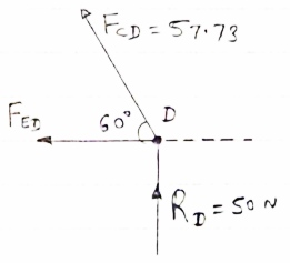
∑FX = 0
 - FED – FCD Cos 60 = 0
 - FED – 57.73 Cos 60 = 0
- FED = -28.86 N
FED = -28.86 N (T)
Member | AB | BC | CD | DE | AE | BE | CE |
Force | 57.73 N | 57.73 N | 57.73 N | 28.86 N | 28.86 N | 57.73 N | 57.73 N |
Nature | C | C | T | T | T | T | C |
Question 9) Explain truss?
Answer 9) Truss:-
A Rigid structure formed by connecting various two force members to each other by using pin joint..
Plane truss: When all member of the truss lies in one plane, Then truss is known as plane truss
Rigid truss:- A truss which do not collapse when external Load is applied on it.
Simple truss:-The structure formed by basic triangle made by Connecting various members are called simple truss.
Question 10) Explain method of section?
Answer 10) Method of section: This method entails passing an imaginary section through the truss to divide it into two sections. The member forces are determined by considering the equilibrium of the part of the truss on either side of the section. This method is advantageous when the axial forces in specific members are required in a truss with several members.

Analysis of Trusses by Method of Section
Sometimes, determining the axial force in specific members of a truss system by the method of joint can be very involving and cumbersome, especially when the system consists of several members. In such instances, using the method of section can be timesaving and, thus, preferable. This method involves passing an imaginary section through the truss so that it divides the system into two parts and cuts through members whose axial forces are desired. Member axial forces are then determined using the conditions of equilibrium. The detailed procedure for analysis by this method is presented below.
Procedure for Analysis of Trusses by Method of Section
•Check the stability and determinacy of the structure. If the truss is stable and determinate, then proceed to the next step.
•Determine the support reactions in the truss.
•Make an imaginary cut through the structure so that it includes the members whose axial forces are desired. The imaginary cut divides the truss into two parts.
•Apply forces to each part of the truss to keep it in equilibrium.
•Select either part of the truss for the determination of member forces.
•Apply the conditions of equilibrium to determine the member axial forces.