Unit 3
Unit 3
Unit 3
Hydraulic Turbines & Pumps
Question 1) how many types of Francis turbine?
Answer 1) Types of Francis Turbines:
There are mainly two types of Francis turbines known as open flume type and closed type.
- In open flume type, the turbine is immersed underwater of the headrace in a concrete chamber and discharges into the tailrace through the draft tube. The main disadvantage of this type is that runner and the guide-vane mechanism is under the water and they are not open either for inspection or repair without draining the chamber.
- In the closed type, the water is led to the turbine through the penstock whose end is connected to the spiral casing of the turbine. The open flume type is used for the plants of 10 meters head whereas; closed type is preferred above 30 meters head.
- The guide vanes are provided around the runner to regulate the water flowing through the turbine The guide vanes provide gradually decreasing area of
flow for all gate openings, so that no eddies are formed, and efficiency does not suffer much even at part load conditions.
Question 2) Draw and explain Francis turbine velocity triangle?
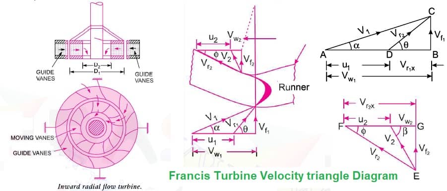
Answer 2)Francis Turbine Velocity triangle Diagram:
The majority of the Francis turbines are inward radial flow type and most preferred for medium heads. The inward flow turbine has many advantages over the outward flow turbine as listed below:
1. The chances of eddy formation and pressure loss are reduced as the area of flow becomes gradually convergent.
2. The runaway speed of the turbine is automatically checked as the centrifugal force acts outwards while the flow is inward.
3. The guide vanes can be located on the outer periphery of the runner, therefore, better regulation is possible.
4. The frictional losses are less as the water velocity over the vanes is reduced.
5. The inward flow turbine can be used for fairly high heads without increasing the speed of the turbine as the centrifugal head supports a considerable part of the supply head.

Inward radial Flow turbine Velocity triangle Diagramwhere,
Vw1 = Velocity of whirl at inlet
Vw2 = Velocity of whirl at outlet
u1= Tangential velocity of whirl at inlet
u2= Tangential velocity of whirl at outlet
Vf1 = Velocity of flow at inlet
Vf2 = Velocity of flow at Outlet
V1 = Absolute velocity of water at the inlet of the runner
V2 = Absolute velocity of water at the Outlet of the runner
Vr1 = Relative Velocity at Inlet of the runner
Vr2 = Relative Velocity at the outlet of the runner
Φ = Vane angle at the exit.
θ = Vane angle at inlet
α = Guide vane angle
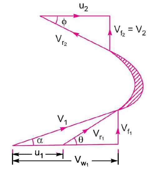
The velocity triangle at inlet and outlet of the Francis turbine is drawn in the same way as in case of inward flow creation turbine. As in case of Francis turbine, the discharge is radial at the outlet, the velocity of whirl at the outlet ( i.e. Vw2 ) will be zero. Hence velocity diagram for Francis turbine is shown below
We Know, absolute velocity at the outlet is 90° i.e. β= 90°

Flow ratio, Kf = Vf1 / √2gH
Flow ratio varies from 0.15 to 0.30
Speed ratio, Ku= u1 / √2gH
Speed ratio varies between 0.6 to 0.9
The ratio of width (B1) to the diameter of the wheel (D1), n= B1/D1
n ratio varies from 0.1 to 0.45
Question 3) Explain efficiency of a Thermal Power Station?
Answer 3)A huge amount of heat is lost in various stages of the plant. Major part of heat is lost in the condenser. That is why the efficiency of thermal plants is quite low.
Thermal Efficiency: The ratio of 'heat equivalent of mechanical energy transmitted to the turbine shaft' to the 'heat of coal combustion' is called as thermal efficiency.
Thermal efficiency of a steam power station= heat equivalent of mechanical energy transmitted to the turbine shaft / heat of coal combustion.
Thermal efficiency of modern thermal power stations is about 30%. It means, if 100 calories of heat are produced by coal combustion, the mechanical energy equivalent of 30 calories will be available at the turbine shaft.
Overall Efficiency: The ratio of 'heat equivalent of electrical output' to the 'heat of coal combustion' is called as overall efficiency.
The overall efficiency of a thermal plant is about 29% (slightly less than the thermal efficiency).
Question 4) Discuss the efficiencies of Francis turbine?
Answer 4)Efficiencies of Francis Turbines:
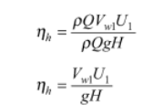
1. Hydraulic efficiency:
It is defined as the ratio of the power produced by the turbine runner and the power supplied by the water at the turbine inlet.

2. Volumetric efficiency:
- It is possible some water flows out through the clearance between the runner and casing without passing through the runner.
- Volumetric efficiency is defined as the ratio between the volume of water flowing through the runner and the total volume of water supplied to the turbine.
3. Mechanical efficiency:
The power produced by the runner is always greater than the power available at the turbine shaft. This is due to mechanical losses at the bearings, windage losses and other frictional losses.

4. Overall efficiency:
This is the ratio of power output at the shaft and power input by the water at the turbine inlet.

Question 5) Explain compressor and types?
Answer 5)Compressor:
The usage of compressed air is not limited only to industries, but they are also used in manufacturing, welding, constructions, power plants, ships, automobile plants, painting shops, and for filling breathing apparatus too. Thus there are so many types of air compressors used specifically for the above purposes

Types of Air Compressors:
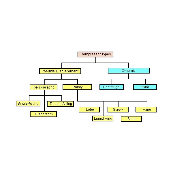
Compressors are classified in many ways out of which the common one is the classification based on the principle of operation.
Types of Compressors:
1. Positive Displacement and
2. Roto-Dynamic Compressors.
Positive displacement compressors cab be further divided into Reciprocating and rotary compressors.
Under the classification of reciprocating compressors, we have
- In-line compressors,
- “V”-shaped compressors,
- Tandem Piston compressors.
- Single-acting compressors,
- Double-acting compressors,
- Diaphragm compressors.
The rotary compressors are divided into
- Screw compressors,
- Vane type compressors,
- Lobe and scroll compressors and other types.
Under the Roto-dynamic compressors, we have
- Centrifugal compressors, and the
- Axial flow compressors.
The compressors are also classified based on other aspects like
- Number of stages (single-stage, 2-stage and multi-stage),
- Cooling method and medium (Air cooled, water cooled and oil-cooled),
- Drive types ( Engine driven, Motor driven, Turbine driven, Belt, chain, gear or direct coupling drives),
- Lubrication method (Splash lubricated or forced lubrication or oil-free compressors).
- Service Pressure (Low, Medium, High)
Question 6) Explain the difference between Francis, pelton and Kaplan turbines?
Answer 6)Following are the differences between Pelton wheel, Francis and Kaplan turbine:
Pelton wheel is an impulse turbine where static pressure head of water is converted into mechanical energy.
On the other hand Francis and Kaplan turbines are reaction turbine where dynamic pressure head of water is converted into mechanical energy.
In impulse turbine change in momentum gives the force applied on the buckets hence work done on the runner. But in reaction turbines blades are designed as a converging passage (in converging passage pressure of water decreases and velocity increase) between the blades so pressure energy is converted to mechanical energy.
Impulse turbine is used where high head is available.
Francis turbine is for medium head and Kaplan is for low head.
Similarly Specific speed is inversely related to heads. So, for impulse turbine specific speed is low, for Francis medium and for Kaplan it is high.Pelton wheel is used where high head is available because static pressure head of water is used in Pelton wheel.
Francis turbine is a mixed flow type reaction turbine where both static and dynamic pressure head of water is used. So it is used where medium head is available.
Kaplan turbine is an axial flow reaction turbine where dynamic head of water is used. So it is used where low head is available.
Question 7) Difference between Pump and Compressor?
Answer 7) Difference between pump and compressor:
S. No. | Pump | Compressor |
1. | It is used to move the fluid from one place to another at | It is used to increase pressure or potential energy of |
2. | It increase pressure of fluid by move it at higher height. | It increases pressure of fluid by compressing it. |
3. | There is no change volume from inlet to outlet of pump. | There is change in volume from inlet to outlet from the |
4. | It is used to transport liquid like water, oil etc. | It is used to transport gases. |
5. | The may or may not change in pressure of fluid. | There must be change in pressure of fluid. |
6. | It is mostly used to increase energy of incompressible | It is mostly used to increase energy of compressible fluid. |
7. | It does not have storage. It only sucks the fluid from one | It has storage capacity. It can store gases and deliver it |
Question 8) what are Difference between Turbine and Pump
Answer 8) Difference between Turbine and Pump
1. In terms of flow of energy: In turbine, input is of hydraulic energy (water under pressure) and output is of mechanical energy (torque of the shaft). In pump, input is of mechanical energy (torque of the shaft) and output is of hydraulic energy (water under pressure).
2. Hydraulic pressure head: Available turbine head decreases with increasing flow (friction losses). Total dynamic head to be generated by pump increases with increasing flow.
3. Direction of rotation: Turbine runner rotates in the opposite direction of a pump impeller.
4. Direction of Torque: In both, in the turbine and in the pump direction of torques is in the same direction.
Question 9) Difference between Impulse and Reaction Turbine
Answer 9) the main difference between Impulse and Reaction Turbine
S.no | Impulse Turbine | Reaction Turbine |
1. | In an impulse turbine, the steam flows through the nozzle and strike on the moving blades. | In the reaction turbine, first, the steam flows through the guide mechanism and then flows through the moving blades. |
2. | Steam strikes on the buckets with kinetic energy. | The steam glides over the moving blades with both pressure and kinetic energy. |
3. | During the flow of steam through moving blades, its pressure remains constant. | During the flow of steam through moving blades its pressure reduces. |
4. | The steam may or may not be admitted to the whole circumference. | The steam must be admitted over the whole circumference. |
5. | The blades of impulse turbine are symmetrical. | The blades of reaction turbine are not symmetrical. |
6. | While gliding over the blades the relative velocity of steam remains constant. | In reaction turbine, while gliding over the blades the relative velocity of steam increases. |
7. | For the same power developed, the number of stages required is less. | For the same power developed, the number of stages required is more. |
8. | The direction of steam flow is radial to the direction of turbine wheel. | The direction of steam flow is radial and axial to the turbine wheel. |
9. | It requires less maintenance work. | It requires more maintenance work. |
10. | It is suitable for low discharge. | It is suitable for medium and high discharge. |
11. | Pelton Wheel is the example of impulse turbine. | Francis turbine, Kaplan turbine etc. are the examples of reaction |
Question 10)Write efficiency of nuclear power plant?
Answer 10)The Efficiency of the Nuclear Power Plant
The nuclear power plant efficiency can be decided equally to other heat engines because technically the plant is a large heat engine. The sum of electric power generated for every unit of thermal power will provide the plant is thermal efficiency & because of the thermodynamics second law, there is a higher limit to how efficient these power plants can be.
The normal nuclear power plants attain efficiencies approximately 33 to 37%, equivalent to fossil-fuel plants. High temperature & more current designs such as the Generation IV reactors could acquire above 45% efficiency.
Question 11) Describe types of nuclear power plant?
Answer 11) Types of Nuclear Power Plant
There are two types of nuclear power plants such as pressurized water reactor and boiling water reactor.
Pressurized Water Reactor
In this kind of reactor, regular water is used as a coolant. This is kept at extremely high force so that it does not get a boil. A heat exchanger in this reactor transfers the heated water where the water from the secondary coolant circle is changed into vapour. Therefore, this loop is totally free from the material of radioactive. In this reactor, the coolant water works as a moderator. Because of these benefits, these reactors are used most frequently.
Boiling Water Reactor
In this kind of reactor, a single coolant loop is only available. The water is permissible to heat within the reactor. The steam is produced from the reactor when it heads out from the reactor & the steam will flow throughout the steam turbine. The main drawback of this reactor is, the coolant water approaches the fuel rods & the turbine. So, radioactive material could be located over the turbine.
Question 12) In India, how many nuclear plants are there?
Answer 12)there are seven nuclear plants available in India
1) Kudankulam Nuclear Power Plant, located in Tamil Nadu
2) Tarapur Nuclear Reactor, located in Maharashtra
3) Rajasthan Atomic Power Plant, located in Rajasthan
4) Kaiga Atomic Power Plant, located in Karnataka
5) Kalapakkam Nuclear Power Plant, located in Tamil Nadu
6) Narora Nuclear Reactor, located in Uttar Pradesh
7) Kakarapar Atomic Power Plant, located in Gujarat