Module 3
Bipolar Junction Transistors and Electronic measuring instruments
Q1) In a CB IE= 2mA, IC=1.5mA. Calculate IB?
Sol: IE =IB+IC
2= IB+1.5
IB=0.5mA
Q2) In a CB current amplification factor is 0.9. If emitter current is 1.2mA. Determine the value of base current?
Sol: α = 0.9
IE =1.2mA
α = IC/ IE
IC = α IE =0.9 x 1.2 = 1.08mA
IE =IB+IC
1.2= IB+1.08
IB= 0.12mA
Q3) In a CB connection IC=1.0mA and IB= 0.02mA. Find the value of current amplification factor?
Sol: IE =IB+IC =1+0.02 = 1.02mA
α = IC/ IE
α = 1.0/1.02 = 0.98
Q4) In a CB connection the emitter current is 0.98mA. If the emitter circuit is open the collector current becomes 40 A. Find total collector current. α =0.92
Sol: ICBO=40 A
A
IC = α IE+ICBO
= (0.92 x 0.98x10-3) + 40x10-6
IC =0.94mA
Q5) In a common base connection, α = 0.95. The voltage drop across 3 kΩ resistance which is connected in the collector is 2.5 V. Find the base current.
Sol: IC = 2.5/3000 = 0.83mA
α = IC/ IE
IE = IC/α =0.83/0.95=0.87mA
IE =IB+IC
0.87 =IB+0.83
IB=0.04mA
Q6) Find the value of β if (i) α = 0.9 (ii) α = 0.98 (iii) α = 0.99.
Sol:  = α/1- α = 0.9/1-0.9 = 9
 = α/1- α = 0.98/1-0.98 = 49
 = α/1- α = 0.99/1-0.99 = 99
Q7) The collector leakage current in a transistor is 200 μA in CE arrangement. If now the transistor is connected in CB arrangement, what will be the leakage current? Given that β = 120.
Sol: ICEO=200 μA
 = 120
= 120
α = /1+
/1+ = 120/121=0.99
ICEO=ICBO/1- α
ICBO= 1.6 μA
Q8) For a certain transistor, IB = 18 μA; IC = 2 mA and β = 60. Calculate ICBO.
Sol: IC =  IB+ICEO
ICEO= IC -  IB= 2x10⁻³-(60x18x10-6) = 0.92mA
α = /1+
/1+ = 60/61=0.98
ICBO= (1- α) ICEO = (1-0.98)x 0.92=15.08 μA
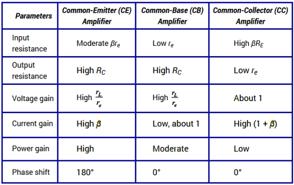
Q9) Compare CB CE and CC configuration?
Sol: 
Q10) Draw and explain input and output characteristics of CB configuration?
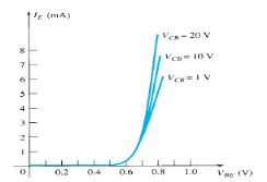
Sol: Input Characteristic Curve

Fig.6: Input Characteristic Curve (Ref. 2)
- It is the relation between the input current IE to the input voltage VBE for various levels of output voltage VCB.
- It is also known as driving point characteristics.
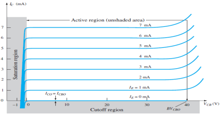
Output Characteristic Curve

Fig.7 : Output Characteristic Curve (Ref. 2)
- It is the relation between the output current IC to the output voltage VCB for various levels of input current IE.
- It is also known as collector set of characteristics.
- It has three basic regions:
- Active Region
Here, base-emitter junction is forward biased and collector-base junction is reverse biased.
As input current IE increases above zero, output current IC increases to a magnitude equal to IE as determined by the basic transistor current relationship.
So, the first approximation determined by the curve is
IC ≈ IE
2. Cut-off Region
It is defined as the region where the collector current IC is equal to 0A.
Here, the base-emitter junction and the collector-base junction both are in reverse bias.
3. Saturation Region
It is the region that lies towards the left of VCB = 0V.
Here, the base-emitter junction and the collector-base junction both are in forward bias.