Unit - 1
Basics of Engineering Graphics and Drawing
Q1) Explain the Types of Lines
A1) Visible Outlines, Visible Edges: (Continuous wide lines).
2. Dimension Lines: (Continuous narrow Lines).
3. Extension Lines: (Continuous narrow Lines)
4. Construction Lines: (Continuous narrow Lines.
5. Hatching / Section Lines: (Continuous Narrow Lines)
6. Guide Lines: (Continuous Narrow Lines)
7. Break Lines: (Continuous Narrow Freehand Lines)
8. Break Lines: (Continuous Narrow Lines with Zigzags)
9. Dashed Narrow Lines: (Dashed Narrow Lines)
10. Center Lines: (Long-Dashed Dotted Narrow Lines)
11. Cutting Plane Lines:
12. Border Lines
Q2) Explain Principles of Dimensioning
A2)
1. All dimensional information necessary to describe a component clearly and completely shall be written directly on a drawing.
2. Each feature shall be dimensioned once only on a drawing, i.e., dimension marked in one view need not be repeated in another view.
3. Dimension should be placed on the view where the shape is best seen
4. As far as possible, dimensions should be expressed in one unit only preferably in millimeters, without showing the unit symbol (mm).
5. As far as possible dimensions should be placed outside the view
6. Dimensions should be taken from visible outlines rather than from hidden lines
7. No gap should be left between the feature and the start of the extension line
8.Crossing of center lines should be done by a long dash and not a short dash
Q3) Explain in Detail Types of Projections
A3)
1. Parallel projections
i Orthographic projections
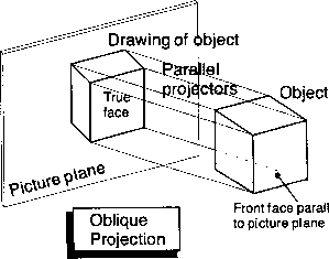
ii. Oblique Projections
2. Perspective projection
Parallel projections
It is a type of projection the line of the 3D object never intersects with each other.
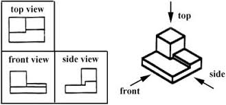
i) Orthographic: A way to show the object in 2D plan surface in which the projection line is perpendicular to surface. are drawn as multi view drawings, which show flat representations of principal views of the subject. Orthographic drawings are useful especially when a design has been developed to a stage whereby it is almost ready to manufacture.
Multiview: When more than one projection planes are used the result is multi view projection. It has the quality that these views are arranged in systematic manner so that reader can conceptualize it easily. They also called 1st angle projections or 3rd angle projections.
Axonometric: means to measure along axes. This type of projections used to draw an object when it is rotated along one or more of its axes relative to the plane of projection it has 3 types 1) Isometric 2) Dimetric 3) Trimetric.
Isometric: drawings consist of two-dimensional drawings that are tilted at some angle to expose other views and give the viewer the illusion that what he or she is viewing is a three-dimensional drawing. The way to draw 3D view of an object in which the horizontal edge is drawn on the 30° angle and vertical are perpendicular from horizontal base.
ii. Oblique:
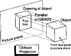
Projection is a simple type of technical drawing of graphical projection used for producing two-dimensional (2D) images of three-dimensional (3D) objects. Oblique projection is commonly used in technical drawing.
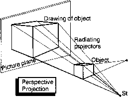
2.Perspective projection: is a type of drawing that graphically approximates on a planar (two-dimensional) surface the images of three-dimensional objects so as to approximate actual visual perception. It is sometimes also called perspective view or perspective drawing or simply perspective.
approximate actual visual perception. It is sometimes also called perspective view or perspective drawing or simply perspective.
Q5) What is 1st angle projection?
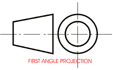
A5) The object lies In between the observer and the plane of projection. The plane of projection Is always behind the object.
2. The object is assumed to be placed in first quadrant.
3. The front view or the elevation Is always above the top view or the plan.
4. The right-hand end view/side view Is drawn to the left- and left-hand end view Is drawn to the right.
5. The plane of projection may or may not be transparent. 6. It Is represented by the following symbol
Q6) What is 3rd angle projection?
A6) Third Angle Method
1. Between the observer and the object ore transparent planes of projection. The plane of projection is always in front of the object.
2. The projections are drawn assuming that Uie object is situated in third quadrant. 3. The front view Is always below the top view.
4. The right-hand end view is drawn to the right- and left-hand end view Is drawn to the left.
5. The plane of projection Is always transparent.
6. It Is represented by the following symbol
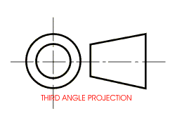
Q7) Explain true length concept with an example.
A7) Hold a pencil in your hand and open a note-book in such a way that some pages are on the table and some pages are held perpendicular to the table top. Consider these as two planes HP and VP. Put one end of the pencil on the HP and let it make some angle with HP.
Make the pencil parallel to VP (imagine the pencil to be a line). Under the condition if the line is projected on HP and VP, its projections will be as shown in following figure.

The elevation of the line a′b′ will be true length, the angle θ will also be true angle but plan ab will be shorter than true length. The length ab is a function of angle θ. If θ is increased, ab will be reduced further. Now consider the pencil parallel to HP and making some angle φ with VP. Its projections will be as shown in following figure.
The length of plan is True length TL, the angle made by this plan with VP, i.e., with XY line is true angle φ, and the length of elevation is a function of angle φ. Elevation is parallel to XY (in second case, the line is given parallel to HP, while in this case the elevation is a line parallel to XY and the plan of the line is TL, the angle made φ is true angle). From the example, we see that in first case when the line was parallel to VP, the elevation of the line is TL, the angle made, i.e., θo, is also true angle and the plan is a line parallel to X-Y. Hence, learn a rule that if the projections of the line are given and if one of the views (plan or elevation) is parallel to XY, the other view MUST BE true length and angle made by this TL will be true angle. Its reverse is also true, i.e., from among the views of a line, if one view is TL, the other view MUST BE parallel to X-Y.
Q8) A line AB 60 mm long has its end 20 mm above HP and 30 mm in front of VP. The line is kept perpendicular to HP and parallel to VP. Draw its projections. Also mark the traces.
A8) Assume that end A of the line is nearer to HP. The front view a’b’ is a line having true length. The top view is a point, the end b of which is visible and a is invisible which is enclosed in (). The line is extended to meet HP to obtained the horizontal trace (HT). No vertical trace (VT) is obtained because the line is kept parallel to VP.

The projections obtained are drawn with reference to XY line as shown in Fig.(ii). (You should not draw diagram (i) in the examination. This diagram is given for explanation only.)
1. Mark the projections of the end A by considering it as a point. Its front view a’ is 20 mm above XY and the top view a is 30 mm below XY.
2. The front view of the line a’b’ is obtained by drawing a line perpendicular to XY from a’ and having a length of 60 mm.
3. Top view of the line is obtained by projecting the other end b which coincides with a. The invisible end a is enclosed in ().
4. The horizontal trace (HT) is marked coinciding with the top view of the line. NO vertical trace (VT) is obtained.