Unit – 2
A.C. Circuits
Q1) Explain the sinusoidal signal?
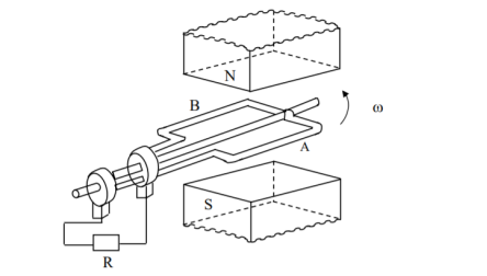
Schematic diagram for single phase ac generation
A multi-turn coil is placed inside a magnet with an air gap as shown in Figure. The flux lines are from North Pole to South Pole. The coil is rotated at an angular speed, ω = 2π n (rad/s).
n = w/2π = speed of the coil (rev/sec or rps)
N = 60 . n = speed of the coil (rev/min or rpm)
l = length of the coil
b = width of the diameter
T = turns of the coil
B= flux density in the air gap (Wb/m2 )
v = π . b. n (tangential velocity of the coil)
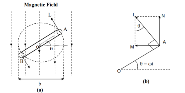
(a) Coil position
(b) Details
At a certain instant t, the coil is an angle (rad), θ = ωt with the horizontal
The emf (V) induced on one side of the coil (conductor) is B l v sinθ , θ can also be termed as angular displacement.
The emf induced in the coil (single turn) is θ = 2B l π b n sinθ
The total emf induced or generated in the multi-turn coil is e(θ )= T2B l π b n sinθ = 2 π B l b n T sin  = Em sin
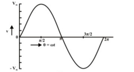
This emf as a function of time, can be expressed as, e(t) = Em sin wt . The graph of e(t) or e( ) which is a sinusoidal waveform s show in figure .
The area of the coil (m 2 ) = a = lb .
Flux cut by the coil (Wb) = ɸ = a . B = l . b . B
Flux linkage (wb) = 
It may be noted these values of flux φ and flux linkage ψ , are maximum, with the coil being at horizontal position, θ = 0 . These values change, as the coil moves from the horizontal position as shown in the figure (b).
The maximum value of the induced emf is
Em = 2 π n B l b T = 2π n ɸ T = 2π n Ѱ= w Ѱ = Ѱ . d
Determination of frequency (f) of the emf generated is
f = w/ (2π) = n , no of poles being 2 that is having only one pole pair.
In the ac generator no of poles = p and the speed (rps) = n, then the frequency in Hz or cycles/sec is
F= no of cycles / sec = no of cycles per rev x no of rev per sec = no of pairs of poles x bno of rev per sec = (p/2) n
Or f = pN/120 = p/2. w/2π
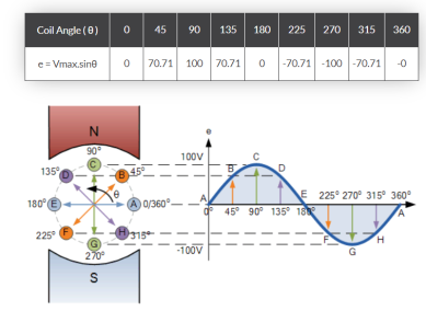
The points on the sinusoidal waveform are obtained by projecting across from the various positions of rotation between 0o and 360o to the ordinate of the waveform that corresponds to the angle, θ and when the wire loop or coil rotates one complete revolution, or 360o, one full waveform is produced.
From the plot of the sinusoidal waveform we can see that when θ is equal to 0o, 180o or 360o, the generated EMF is zero as the coil cuts the minimum amount of lines of flux. But when θ is equal to 90o and 270o the generated EMF is at its maximum value as the maximum amount of flux is cut.
Therefore, a sinusoidal waveform has a positive peak at 90o and a negative peak at 270o. Positions B, D, F and H generate a value of EMF corresponding to the formula:
e = Vmax.sinθ.
Then the waveform shape produced by our simple single loop generator is commonly referred to as a Sine Wave as it is said to be sinusoidal in its shape.
Q2) Explain the phasor in polar and rectangular form ?
The instantaneous voltage equation is given by
Vt= vm sin (w t +Ø)
which can be represented by polar form
vt =  L Ø
L Ø
where  = peak value
e.g. vt =30 sin (w t + 90 )
)
polar form  < 90
< 90
polar form is suitable for multiplication and division of phases.
2. Rectangular Form:
The instantaneous voltage equation is given by
Vt = v m sin (w t +Ø)
which can be represented by Rectangular Form
vt = 
where X =  or Vm cos Ø
Y = or Vm sin Ø
Vt = v m cos Ø + i vm sin Ø
e.g. 30 sin (w t + 90)
Rectangular form vt = 30 cos 90 + i 30 sin 90
 Rectangular Form is suitable for addition and subtraction of Phases
Q3) Explain AC circuit using pure resistance?
Ac circuit containing pure resisting
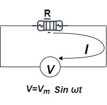
Consider Circuit Consisting pure resistance connected across ac voltage source
V = Vm Sin ωt ①
According to ohm’s law i =  =
= 
But Im = 
 ②
②
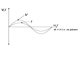
Phases diagram
From ① and ② phase or represents RMD value.
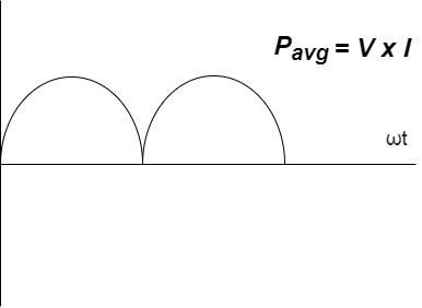
Power P = V. i
Equation P = Vm sin ω t Im sin ω t
P = Vm Im Sin2 ω t
P =  -
- 

Constant fluctuating power if we integrate it becomes zero

Average power
Pavg = 
Pavg = 
Pavg = Vrms Irms
Power ware form [Resultant]
Q4) Explain inductance and capacitance in AC circuits?
Ac circuit containing pure Inductors
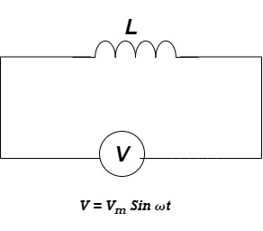
Consider pure Inductor (L) is connected across alternating voltage. Source
V = Vm Sin ωt
When an alternating current flow through inductance it set ups alternating magnetic flux around the inductor.
This changing the flux links the coil and self-induced emf is produced
According to faradays Law of E M I
e = 
at all instant applied voltage V is equal and opposite to self-induced emf [ lenz’s law]
V = -e
 =
= 
But V = Vm Sin ωt

 dt
dt
Taking integrating on both sides
 dt
dt
 dt
dt

 (-cos
(-cos  )
)


but sin (– ) = sin (+
 )
)
 sin (
sin ( -
-  /2)
/2)
And Im= 
 /2)
/2)
 /2
/2
= -ve
= lagging
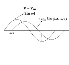
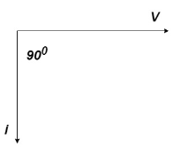
= I lag v by 900
Waveform:
Phasor:
Power P = Ѵ. I
= Vm sin wt Im sin (wt  /2)
/2)
= Vm Im Sin wt Sin (wt –  /s)
/s)
 ①
①
And
Sin (wt -  /s) = - cos wt ②
Sin (wt –  ) = - cos
 sin 2 wt from ① and ②
The average value of sin curve over a complete cycle is always zero

 Pavg = 0
Ac circuit containing pure capacitors:
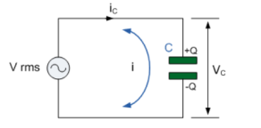
Consider pure capacitor C is connected across alternating voltage source
Ѵ = Ѵm Sin wt
Current is passing through capacitor the instantaneous charge ɡ produced on the plate of capacitor
ɡ = C Ѵ
ɡ = c Vm sin wt
the current is rate of flow of charge

i= (cvm sin wt)
i = c Vm w cos wt
then rearranging the above eqth.
i =  cos wt

 = sin (wt +
  X/2)
X/2)
i =  sin (wt + X/2)
but 
 X/2)
X/2)

= leading
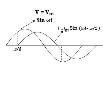
= I leads V by 900
Waveform :
Phase
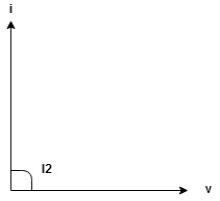
Power P= Ѵ. i
= [Vm sinwt] [ Im sin (wt + X/2)]
= Vm Im Sin wt Sin (wt + X/2)]
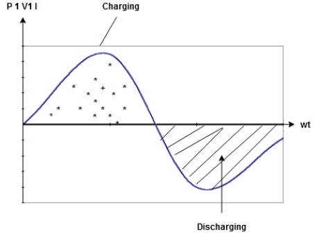
 (cos wt)


 to charging power waveform [resultant].
Q5) Explain Admittance and Impedance?
Impedance
Two impedances in parallel
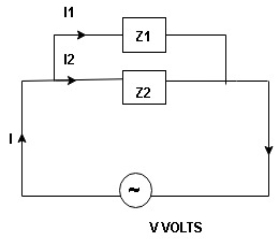
I1 an I2 can be founded using current division rules
It states that the current in one branch is the products, ratio of total current and opposite branch (impedance / reactance / resistance) to the total (impedance / reactance / resistance)
 above ckt. Can be found using following steps


 or z
or z
Admittance
Admittance is defined as reciprocal of the impedance (Z)
It is denoted by Y and its unit Siemens (S)
 Admittance Y =
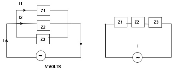
I = I1 + I2 + I3
 =
=  +
+  +
+ 
 =
=  +
+  +
+ 
Y = Y1 + Y2 + Y3
Rationalize the expression of Y as follows

Y = 
But Z2 = R2 + X2
 Y =
Y = 
Let  + G + conductance
 = B = susceptance
 Y = G
Y = G  jB
jB
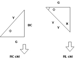
Conductance (G) : it is defined as the ratio of resistance R and the squared impedance (Z2) and it is measured in Siemens or mho 
G = 
Theoretically G = reciprocal od resistance.
Susceptance (B) :it is defined as the ratio of reactance X and the squared impedance (Z2) or mho 
B = 
Theoretically B = reciprocal od resistance.
Q6) Explain average and rms values?
Average Value:
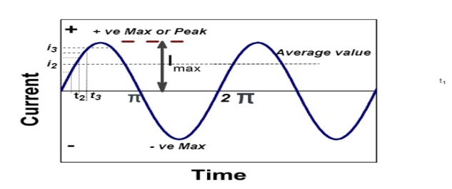
The arithmetic mean of all the value over complete one cycle is called as average value

 =
= 
For the derivation we are considering only hall cycle.
Thus  varies from 0 to ᴫ
i = Im Sin


Solving
We get


Similarly, Vavg=
The average value of sinusoid ally varying alternating current is 0.636 times maximum value of alternating current.
RMS value: Root mean square value
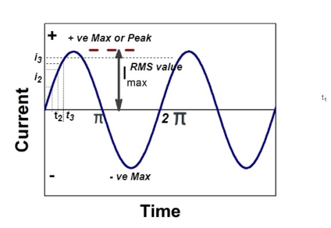
The RMS value of AC current is equal to the steady state DC current that required to produce the same amount of heat produced by ac current provided that resistance and time for which these currents flows are identical.

I rms = 
Direction for RMS value:
Instantaneous current equation is given by
i = Im Sin 
but 
I rms = 
= 
=
=
Solving
=
=
Similar we can derive
V rms=  or 0.707 Vm
 the RMS value of sinusoidally alternating current is 0.707 times the maximum value of alternating current.
Peak or krest factor (kp) (for numerical)
It is the ratio of maximum value to rms value of given alternating quantity
Kp = 
 Kp =
Kp = 
 Kp = 1.414
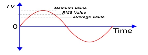
Form factor (Kf): For numerical “It is the ratio of RMS value to average value of given alternating quality”.


Q7) Explain apparent power and complex power?
S= V × I
Unit - Volte- Ampere (VA)
In kilo – KVA
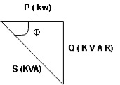
2. Power factor, cos(Φ), is an important part of an AC circuit that can also be expressed in terms of circuit impedance or circuit power. Power factor is defined as the ratio of real power (P) to apparent power (S), and is generally expressed as either a decimal value, for example 0.95, or as a percentage: 95%.
3. Complex power (in VA) is the product of the rms voltage phasor and the complex conjugate of the rms current phasor. As a complex quantity, its real part is real power P and its imaginary part is reactive power Q.
Q8) Explain series RL and RC circuits?
Series R-L Circuit
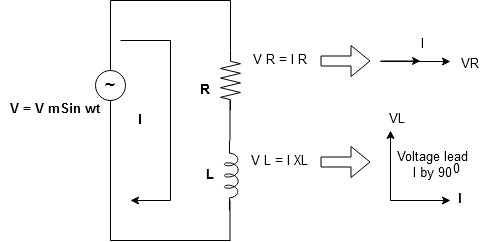
Consider a series R-L circuit connected across voltage source V= Vm sin wt
As some I is the current flowing through the resistor and inductor due do this current voltage drops arcos R and L R  VR = IR and L
  VL = I X L
 Total V = VR + VL
V = IR + I X L  V = I [R + X L]


Take current as the reference phasor : 1) for resistor current is in phase with voltage 2) for Inductor voltage leads current or current lags voltage by 90 0.
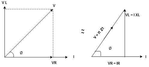
For voltage triangle
Ø is power factor angle between current and resultant voltage V and
V = 

V = 

where Z = Impedance of circuit and its value is  =
= 
Impedance Triangle
Divide voltage triangle by I
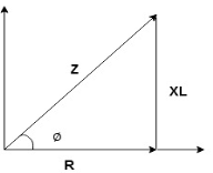
Rectangular form of Z = R+ixL
and polar from of Z =  L +
L + 
(+ j X L +  because it is in first quadrant )
Where  =
= 
 + Tan -1
Current Equation :
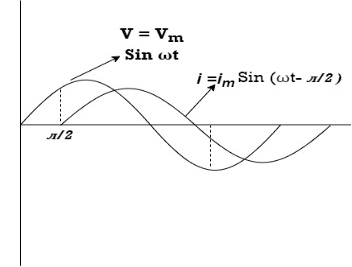
From the voltage triangle we can sec. that voltage is leading current by  or current is legging resultant voltage by
Or i =  =
=  [ current angles - Ø )

Resultant Phasor Diagram from Voltage and current eqth.
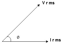
Wave form
Power equation
P = V .I.
P = Vm Sin wt Im Sin wt – Ø
P = Vm Im (Sin wt) Sin (wt – Ø)
P =  (Cos Ø) - Cos (2wt – Ø)
Since 2 sin A Sin B = Cos (A-B) – Cos (A+B)
P =  Cos Ø -
  Cos (2wt – Ø)

①②
Average Power
pang =  Cos Ø
Cos Ø
Since ② term become zero because Integration of cosine come from 0 to 2ƛ
 pang = Vrms Irms cos Ø watts.
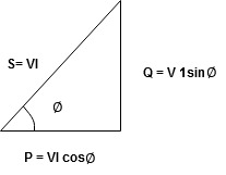
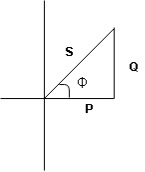
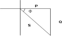
Power Triangle :
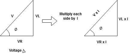
From 
VI = VRI + VLI B
Now cos Ø in  A =
A = 
 ①
①
Similarly Sin  =
= 


Apparent Power Average or true Reactive or useless power
Or real or active
-Unit (VI) Unit (Watts) C/W (VAR) denoted by (Ø)
Denoted by [S] denoted by [P]
Power  for R L ekt.
Series R-C circuit
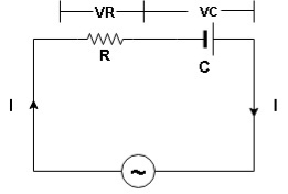
V = Vm sin wt
VR

 I
I
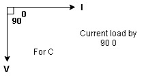
R and C  voltage drops across.
R and C  R
R  VR = IR
And C  Vc = I
 c
c


 V =
V =  lZl
lZl
Voltage triangle : take current as the reference phasor 1) for resistor current is in phase with voltage 2) for capacitor current leads voltage or voltage lags behind current by 900
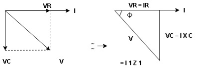
Where Ø is power factor angle between current and voltage (resultant) V
And from voltage
V = 
V = 
V = 
V =  lZl
lZl
Where Z = impedance of circuit and its value is lZl = 
Impendence triangle :
Divide voltage  by
by  as shown
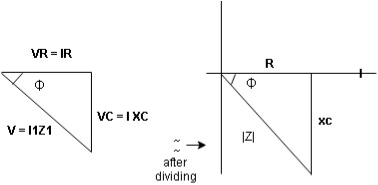
Rectangular from of Z = R - jXc
Polar from of Z = lZl L - Ø
( - Ø and –jXc because it is in fourth quadrant ) where
lZl = 
and Ø = tan -1 
Current equation :
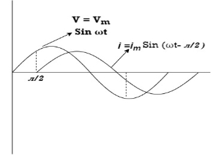
from voltage triangle we can see that voltage is lagging current by Ø or current is leading voltage by Ø
 i = IM Sin (wt + Ø) since Ø is +ve
Or i =  for RC
 LØ [ resultant current angle is + Ø]
Resultant phasor diagram from voltage and current equation

Resultant wave form :
Power Equation :
P = V. I
P = Vm sin wt. Im Sin (wt + Ø)
= Vm Im sin wt sin (wt + Ø)
2 Sin A Sin B = Cos (A-B) – Cos (A+B)
 -
- 
Average power
pang =  Cos Ø
Cos Ø
since 2 terms integration of cosine wave from 0 to 2ƛ become zero
 2 terms become zero
 pang = Vrms Irms Cos Ø
Power triangle RC Circuit:
Q9) Explain Parallel R-L and R-C circuits?
Parallel R-L circuit
In RL parallel circuit resistor and inductor are connected in parallel with each other and this combination is supplied by voltage source Vin. The output voltage of circuit is Vout. Since the resistor and inductor are connected in parallel, the input voltage is equal to output voltage but the currents flowing in resistor and inductor are different.
The parallel RL circuit is not used as filter for voltages because in this circuit, the output voltage is equal to input voltage and for this reason it is not commonly used as compared to series RL circuit.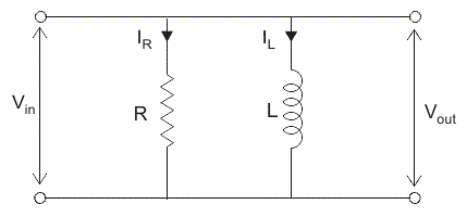
Let us say: IT = the total current flowing from voltage source in amperes.
IR = the current flowing in the resistor branch in amperes.
IL = the current flowing in the inductor branch in amperes.
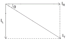
θ = angle between IR and IT.
So the total current IT,
I2T = I2R + I2L
In complex form the currents are written as,
IR = Vin /R
IL = Vin / jwL
IL = -j Vin/wL (where 1/j =-j)
Therefore, total current IT = Vin/ R-j/Vin/wL
Impedance of Parallel RL Circuit
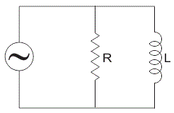
Let, Z = total impedance of the circuit in ohms.
R = resistance of circuit in ohms.
L = inductor of circuit in Henry.
XL = inductive reactance in ohms.
Since resistance and inductor are connected in parallel, the total impedance of the circuit is given by,
1/Z = 1/R + 1/jXL
Z = R * (jXL)/ R +jXL
In order to remove “j” from the denominator multiply and divide numerator and denominator by (R – j XL),
Z = R * (jXL) / R+jXL) * R-jXL/ R-jXL
= j R2 XL – j2 R2 XL2 / R2 + XL2
Since j2 = -1
RXL2 + j R2 XL / R2 + XL2
Z = RXL2 / R2 + XL2 + j R2 XL / R2 + XL2
Parallel RC circuit
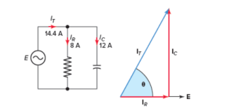
In a parallel RC circuit, the line current leads the applied voltage by some phase angle less than 90 degrees but greater than 0 degrees. The exact angle depends on whether the capacitive current or resistive current is greater. If there is more capacitive current, the angle will be closer to 90 degrees, while if the resistive current is greater, the angle is closer to 0 degrees.
The value of the phase angle can be calculated from the values of the two branch currents using the following equation:
 = tan-1 Ic/IR
Current in Parallel RC Circuit
For the parallel RC circuit shown in Figure 3, determine:
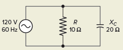
Figure Circuit .
Solution:
a. IR=ER=120V10 Ω =12Aa. IR=ER=120V10 Ω =12A
b. IC=EXC=120V20 Ω =6Ab. IC=EXC=120V20 Ω =6A
c. IT=√I2R+I2C=√122+62=13.4Ac. IT=IR2+IC2=122+62=13.4A
d.θ=tan−1(ICIR)=tan−1(612)=26.6od.θ=tan−1(ICIR)=tan−1(612)=26.6o
e. IT=13.4∠26.6ooIR=12∠0oIC=6∠90oe. IT=13.4∠26.6ooIR=12∠0oIC=6∠90o
f. IT=12+j6IR=12+j0IC=0+j6f. IT=12+j6IR=12+j0IC=0+j6
Parallel RC Circuit Impedance
The impedance (Z) of a parallel RC circuit is similar to that of a parallel RL circuit and is summarized as follows:
Z = RXC / √ R2 + X 2 C
Q10) Explain series and parallel RLC circuits?
R-L-C series circuit
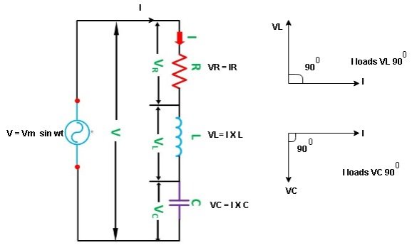
Consider ac voltage source V = Vm sin wt connected across combination of R L and C. when I flowing in the circuit voltage drops across each component as shown below.
VR = IR, VL = I  L, VC = I
  C
C
① XL> XC, ② XC> XL, ③ XL = XC
① XL > XC: Since we have assumed XL> XC
 Voltage drop across XL> than XC
 VL> VC A

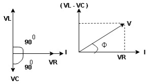
VL and VC are 180 0 out of phase .
Therefore cancel out each other
 Resultant voltage triangle
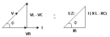
Now V = VR + VL + VC c phasor sum and VL and VC are directly in phase opposition and VL
 VC
VC their resultant is (VL - VC).
From voltage triangle
V = 
 V =
V = 
 V = I
V = I 

Impendence  : divide voltage
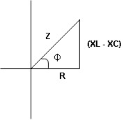
Rectangular form Z = R + j (XL – XC)
Polor form Z =  l + Ø B
Where  =
= 
And Ø = tan-1 
i =  from B
i =  L-Ø C
L-Ø C
as VL VC the circuit is mostly inductive and
  I lags behind V by angle Ø
 Since i =
  L-Ø
L-Ø
 i = Im Sin (wt – Ø) from c


 the voltage drops across XC
  than XL
 XC
XC  XL (A)
 voltage triangle considering condition (A)
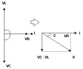
 Resultant Voltage
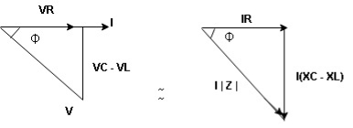
Now V = VR + VL + VC  phases sum and VL and VC are directly in phase opposition and VC
 VL
VL  their resultant is (VC – VL)
From voltage 
V = 
V = 
 V =
V = 
 V =
V = 

 Impedance
  : Divide voltage
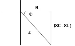
Polar form : Z =  L -
L -
Where 
And Ø = tan-1 – 


as VC  the circuit is mostly capacitive and
  leads voltage by angle Ø
since i =  L + Ø
L + Ø
 Sin (wt – Ø) from C

ɡȴ XL= XC then VL= VC and they are 1800 out of phase with each other  they will cancel out each other and their resultant will have zero value.
Hence resultant V = VR and it will be in phase with I as shown in below phasor diagram.
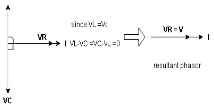
From above resultant phasor diagram
V =VR + IR
Or V = I  lZl
lZl
Because lZl + R
Thus Impedance Z is purely resistive for XL = XC and circuit current will be in phase with source voltage.

 Since VR=V Øis zero when XL = XC
  power is unity
ie pang = Vrms I rms cos Ø = 1 cos o = 1
maximum power will be transferred by condition. XL = XC
AC parallel circuit:
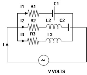
Total I = I1 + I2 + I3
As parallel circuit  applied total voltahe V is same at each branch
I = I1 + I2 + I3
=  =
=  +
+  +
+ 
 =
=  +
+  +
+  +……
+……
Q11) Explain quality factor and bandwidth?
Quality factor / Q factor
The quality of resonance circuit is measured in terms of efficiency of L and C to stare energy and the efficiency of L and C to store energy as measured in terms of a factor called quality factor or Q factor it is expressed as
Q =  and Q =
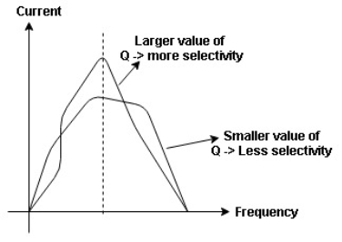
The sharpness of tuning of R-L-C series circuit or its selectivity is measured by value of Q. as the value of Q increases, sharpness of the curve also increases and the selectivity increases.
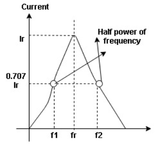
Bandwidth (BW) = f2 = b1
 and
and  are the frequency at which the power delivered to the resistor is reduced to 50% of the power delivered to it at resonance
  these frequencies are called as half power frequency
Bw = fr/Q
Frequency points ƒL and ƒH relate to the lower corner or cut-off frequency and the upper corner or cut-off frequency points respectively were the circuits gain falls off at high and low frequencies. These points on a frequency response curve are known commonly as the -3dB (decibel) points. So the bandwidth is simply given as:
Bandwidth = fH -fL.