Unit – 4
Transformers and Rotating Machines
Q1) Explain Ampere’s Law in Transformers?
The net MMF around a closed path is equal to the total current passing through the interior of the path:
 = total current passing through interior of path.
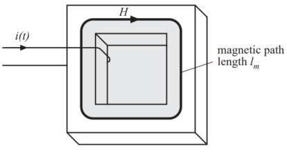
Figure 1. Amperes law
Example: magnetic core.
Wire carrying current i(t) passes through core window. • Illustrated path follows magnetic flux lines around interior of core. For uniform magnetic field strength H(t), the integral (MMF) is H(t)lm. So
F ( t) = H ( t ) l m = i( t )
Relates magnetic field strength H(t) to winding current i(t)
Q2) Explain mutual inductance?
If the secondary coil experiences the same magnetic flux change as the primary assuming perfect containment of the magnetic flux through the common core and has the same number of turns around the core, a voltage of equal magnitude and phase to the applied voltage will be induced along its length.
In the following graph, the induced voltage waveform is drawn slightly smaller than the source voltage waveform simply to distinguish one from the other:
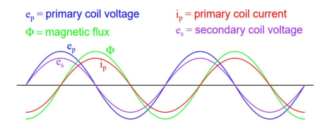
Figure2. Mutual inductance
This effect is called mutual inductance the induction of a voltage in one coil in response to a change in current in the other coil.
Mutual inductance
e2 = M di1/dt
where
e2 = voltage induced in the secondary coil
i1= current in primary coil.
Q3) Explain the construction and working single phase transformer?
The single-phase transformer works on the principle of Faradays Law of electromagnetic induction.
Working of Single Phase Transformer
When the primary of a transformer is connected to an AC supply, the current flows in the coil and the magnetic field build-up. This condition is known as mutual inductance and the flow of current is as per the Faraday’s Law of electromagnetic induction. As the current increases from zero to its maximum value, the magnetic field strengthens and is given by dɸ/dt.
This electromagnet forms the magnetic lines of force and expands outward from the coil forming a path of magnetic flux. The turns of both windings get linked by this magnetic flux. The strength of a magnetic field generated in the core depends on the number of turns in the winding and the amount of current. The magnetic flux and current are directly proportional to each other.
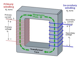
Figure 3.Working-of-single-phase-transformer
As the magnetic lines of flux flow around the core, it passes through the secondary winding, inducing voltage across it. The Faraday’s Law is used to determine the voltage induced across the secondary coil and it is given by:
N. dɸ/dt
where,
‘N’ is the number of coil turns
The frequency is the same in primary and secondary windings.
Thus, we can say that the voltage induced is the same in both the windings as the same magnetic flux links both the coils together. Also, the total voltage induced is directly proportional to the number of turns in the coil.
Let us assume that the primary and secondary windings of the transformer have single turns on each. Assuming no losses, the current flows through the coil to produce magnetic flux and induce voltage of one volt across the secondary.
Due to AC supply, magnetic flux varies sinusoidally and it is given by,
ɸ = ɸmax Sin ωt
The relationship between the induced emf, E in the coil windings of N turns is given by,
E=N (d∅)/dt
E=N*ω*ɸmax cosωtφ
Emax=Nωɸmax
Erms=Nω/√2*ɸmax=2π/√2*f*N*ɸmax
Erms=4.44 fNɸmax
Where,
‘f’ is the frequency in Hertz, given by ω/2π.
‘N’ is the number of coil windings
‘ɸ’ is s the amount of flux in Webers
The above equation is the Transformer EMF Equation. For emf of a primary winding of a transformer E, N will be the number of primary turns (NP), while for the emf, E of a secondary winding of a transformer, the number of turns, N will be (NS).
Construction of Single Phase Transformer
A simple single-phase transformer has each winding being wound cylindrically on a soft iron limb separately to provide a necessary magnetic circuit, which is commonly referred to as “transformer core”. It offers a path for the flow of the magnetic field to induce voltage between two windings.
As seen in the figure above, the two windings are not close enough to have an efficient magnetic coupling. Thus, converging and increasing the magnetic circuit near the coils can enhance the magnetic coupling between primary and secondary windings. Thin steel laminations shall be employed to prevent power losses from the core.
Based on how the windings are wound around the central steel laminated core, the transformer construction is divided into two types
Core-type Transformer
In this type of construction, only half of the windings are wound cylindrically around each leg of a transformer to enhance magnetic coupling as shown in the figure below. This type of construction ensures that magnetic lines of force flow across both the windings simultaneously. The main disadvantage of the core-type transformer is the leakage flux that occurs due to the flow of a small proportion of magnetic lines of force outside the core.
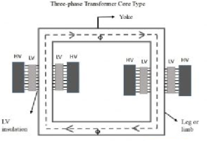
Figure4.core-type-transformer
Shell-type Transformer
In this type of transformer construction, the primary and secondary windings are positioned cylindrically on the center limb resulting in twice the cross-sectional area than the outer limbs. There are two closed magnetic paths in this type of construction and the outer limb has the magnetic flux ɸ/2 flowing. Shell type transformer overcomes leakage flux, reduces core losses and increases efficiency.
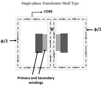
Figure5.single-phase-transformer-shell-type
Phasor diagram
Q4) Explain the emf equation of the transformer?
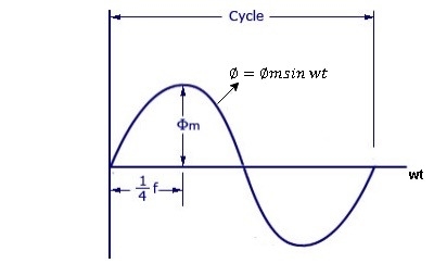
Figure 7. Emf
As primary winding excited by the a sinusoidal alternating voltage an alternating current flows in the winding producing an alternating varying flux Ø
Ø = Øm sin wt
As per Faradays Law of Electromagnetic Induction emf E1 is induced
E1 = N1 
E1 = N1  (Ø Sin wt)
= - N1 Øm w Cos wt
Sin (90-wt)
= - Sin (wt-90)
 E1 = N1 Øm w Sin (wt-90)
 w =
w = 
 E1 =
E1 =  N1 Ø m Sin (wt-90)
Max value of E1 = E max
Is when Sin (wt-90) =  1
1
E1 max =  N1 Ø m
Hence rms value of induced EMF in primary winding
E1 rms =  =
= 
 E1 = 4.44 F Ø m N1
 Similarly RMS value of induced EMF in secondary wdg Is
E2 = 4.44 F Ø m N2
Q5) Explain the equivalent circuit of transformer?
The equivalent circuit diagram of any device can be quite helpful in the pre-determination of the behaviour of the device under the various condition of operation. It is simply the circuit representation of the equation describing the performance of the device.
The simplified equivalent circuit of a transformer is drawn by representing all the parameters of the transformer either on the secondary side or on the primary side. The equivalent circuit diagram of the transformer is shown below:
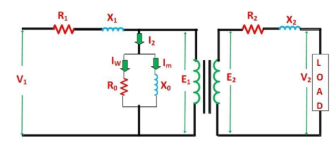
Figure 8.EQUIVALENT CIRCUIT DIAGRAM OF A TRANSFORMER
Let the equivalent circuit of a transformer having the transformation ratio K = E2/E1
The induced emf E1 is equal to the primary applied voltage V1 less primary voltage drop. This voltage causes current I0 no-load current in the primary winding of the transformer. The value of no-load current is very small, and thus, it is neglected.
Hence, I1 = I1’. The no-load current is further divided into two components called magnetizing current (Im) and working current (Iw).
These two components of no-load current are due to the current drawn by a non-inductive resistance R0 and pure reactance X0 having voltage E1 or (V1 – primary voltage drop).
The secondary current I2 is
I2 = I1’/K = I1-Io/K
The terminal voltage V2 across the load is equal to the induced emf E2 in the secondary winding less voltage drop in the secondary winding.
Q6) Define efficiency and regulation of single phase transformer?
Efficiency = (Output Power/ Input Power) x 100 %
= V2 I2 / W1 x 100 % .
Voltage Regulation :
It is the change in the magnitude of secondary voltage from no load to desired load. This change is expressed as a percentage of the no load voltage.
% VR = No load voltage – Desired load voltage / No load voltage x 100%
= E2- V2/ E2 x 100%
Q7) What is an auto transformer?
An auto Transformer is a special types of transformer such that a part of the winding is common to both primary as well as secondary
It has only One winding wended on a laminated magnetic core
With the help of auto Transformer the voltage can be stepped up and stepped down at any desired value
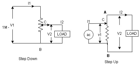
Figure9. Auto Transformer
Fig A shows auto T/F as step down T/F variable terminal B C is connected to load and it acts as secondary wdg.
The position of point C is called as topping point can be selected as per requirement
Fig. B show auto T/F as step up T/F variable terminal B C is connected to supply side ie ac side and it acts as secondary winding
The operating principle of auto Transformer is same as that of 2 winding Transformer
Advantages
Disadvantage :
As low voltage and high voltage sides are not separate then there is always risk of electric shocks when use for high vtg. Applications
Applications
Q8) Explain the working principle of dc motor?
A machine that converts d.c. power into mechanical power is known as a d.c.
motor. Its operation is based on the principle that when a current carrying
conductor is placed in a magnetic field, the conductor experiences a mechanical force.The direction of this force is given by Fleming’s left-hand rule and magnitude is given by;
F = Bil newtons
Basically, there is no constructional difference between a d.c. motor and a d.c. generator.The same d.c. machine can be run as a generator or motor.Working principle of a dc motor can be explained from Fleming’s left-hand rule.
Fleming’s left-hand rule:
Working of D.C. Motor:
Consider a part of a multipolar d.c. motor as shown in the below figure. When the terminals of the motor are connected to an external source of d.c. supply:
(i) the field magnets are excited developing alternate N and S poles;
(ii) the armature conductors carry currents.
All conductors under N-pole carry currents in one direction while all the conductors under S-pole carry currents in the opposite direction.
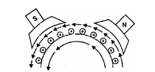
Figure. Conductors
Suppose the conductors under N-pole carry currents into the plane of the paper and those under S-pole carry currents out of the plane of the paper as shown in the above figure. Since each armature conductor is carrying current and is placed in the magnetic field, a mechanical force acts on it. Referring to the above figure and applying Fleming’s left-hand rule, it is clear that force on each conductor is tending to rotate the armature in an anticlockwise direction. All these forces add together to produce a driving torque which sets the armature rotating.
When the conductor moves from one side of a brush to the other, the current in that conductor is reversed and at the same time, it comes under the influence of next pole which is of opposite polarity. Consequently, the direction of the force on the conductor remains the same.
Commutator present will give unidirectional torque. If it's not there then the conductor movement(force) would have been reversed every time when the direction of magnetic field is changed. This is how do a dc motor works.
Q9) Explain the characteristics?
The performance of a d.c. motor under various condition can be judged by the following characteristics :
(i). Torque – Armature current characteristics
(ii). Speed – Armature current characteristics
(iii). Speed-Torque characteristics
Torque – Armature current characteristics
T α ɸ Ia
For a constant values of Rsh and supply voltage V, Ish is also constant and hence flux is also constant.
ɸ α If
Ta α Ia
The equation represents a straight line, passing through the origin as shown in the figure. Torque increases linearily with armature current.
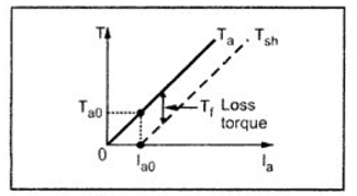
Figure 11. T vs Ia
To generate high starting torque, this type of motor requires a large value of armature current at the start. This may damage the motor hence d.c. shunt motors can develop moderate starting torque and hence suitable for such applications where starting torque requirement is moderate.
Speed Armature current characteristics
N α (V – IaRa/ɸ0
ɸ-constant
N α V – Ia Ra
So as load increases The armature current increases and hence drop IaRa also increases.
Hence for constant supply voltage, V-IaRa decreases and hence speed reduces. But as Ra is very small, for change Ia in from no load to full load, drop IaRA is very small and hence drop in speed is also not significant from no load to full load.
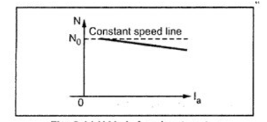
Figure 12.N vs Ia for shunt motor
In d.c. shunt motor >> Speed regulation is an order of 5 to 10 % from no load to full load >> That’s why d.c. shunt motor is also called as constant drive motor..
Speed – Torque Characteristics
T α ɸ Ia
Ta α Ia
N α ( V – IaRa/ɸ)
ɸ-constant
N α V – Ia Ra
So, from these 2 equations, we can conclude that Speed and Torque both has a linear relationship. This characteristics, is similar to speed – Armature current characteristics.
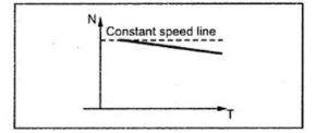
Figure 13.N vs T for shunt motor
This curve shows that the speed almost remains constant through torque changes from no load to full load conditions.
Q10) Explain the construction of three phase induction motor?
Construction of Three Phase Induction Motor:
Figure shows the construction of three phase induction motor. A three phase induction motor has two main parts (i) stator and (ii) rotor.
The rotor is separated from the stator by a small air-gap which ranges from 0.4 mm to 4 mm, depending on the power of the motor.
1. Stator:
|
FIGURE14. Stator |
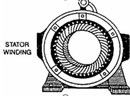
It consists of a steel frame which encloses a hollow, cylindrical core made up of thin laminations of silicon steel to reduce hysteresis and eddy current losses. A number of evenly spaced slots are provided on the inner periphery of the laminations.
The insulated connected to form a balanced 3-phase star or delta connected the circuit. The 3-phase stator winding is wound for a definite number of poles as per requirement of speed.
Greater the number of poles, lesser is the speed of the motor and vice-versa.
When 3-phase supply is given to the stator winding, a rotating magnetic field of constant magnitude is produced. This rotating field induces currents in the rotor by electromagnetic induction.
2. Rotor:
The rotor, mounted on a shaft, is a hollow laminated core having slots on its outer periphery. The winding placed in these slots (called rotor winding) may be one of the following two types:
(i) Squirrel cage type (ii) Wound type
(i) Squirrel cage rotor: It consists of a laminated cylindrical core having parallel slots on its outer periphery.
One copper or aluminium bar is placed in each slot. All these bars are joined at each end by metal rings called end rings.
This forms a permanently short circuited winding which is indestructible. The entire construction (bars and end rings) resembles a squirrel cage and hence the name.
The rotor is not connected electrically to the supply but has current induced in it by transformer action from the stator.
Those induction motors which employ squirrel cage rotor are called squirrel cage induction motors.
Most of 3 phase induction motors use squirrel cage rotor as it has a remarkably simple and robust construction enabling it to operate in the most adverse circumstances.
However, it suffers from the disadvantage of a low starting torque .It is because the rotor bars are permanently short-circuited and it is not possible to add any external resistance to the rotor circuit to have a large starting torque.

(ii) Wound rotor: It consists of a laminated cylindrical core and carries a 3-phase winding, similar to the one on the stator.
The rotor winding is uniformly distributed in the slots and is usually star-connected. The open ends of the rotor winding are brought out and joined to three insulated slip rings mounted on the rotor shaft with one brush resting on each slip ring.
The three brushes are connected to a 3-phase star-connected rheostat as shown in Figure. At starting, the external resistances are included in the rotor circuit to give a large starting torque.
These resistances are gradually reduced to zero as the motor runs up to speed.
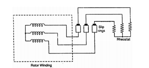
Figure 15. Rotor
The external resistances are used during starting period only. When the motor attains normal speed, the three brushes are short-circuited so that the wound rotor runs like a squirrel cage rotor.
Working Principle:
Q11) Explain three phase synchronous machines?
Three-Phase Synchronous Machine
Q12) Explain the torque speed characteristics?
Torque Speed Characteristic is the curve plotted between the torque and the speed of the induction motor. The equation of the torque is given
 = ks R2 E2 20/ R2 2 + (sX20) 2 ----------------------------(1)
as shown below:
At the maximum torque, the speed of the rotor is expressed by the
NM = NS(1-sM) ----------------------(2)
equation shown below:
The curve below shows the Torque Speed Characteristic:
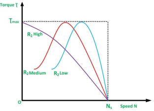
Figure . Torque Speed characteristics.
