|
Therefore, |
|
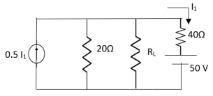
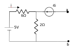
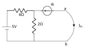
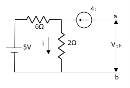
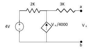
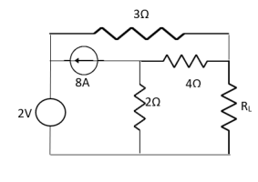
Find Thevenin’s equation
|
|
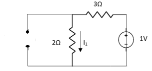
Since, there is no significance of current source |
|
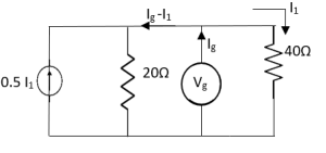
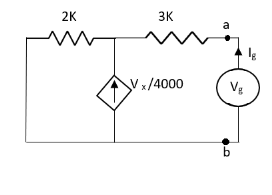
For Rth
By KCL, But,
By KVL, |
|
=
= |
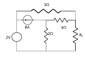
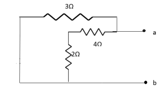
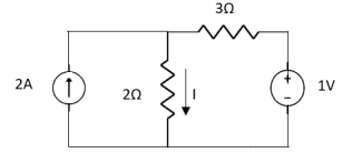
 resistance using superposition theorem.
|
|
|
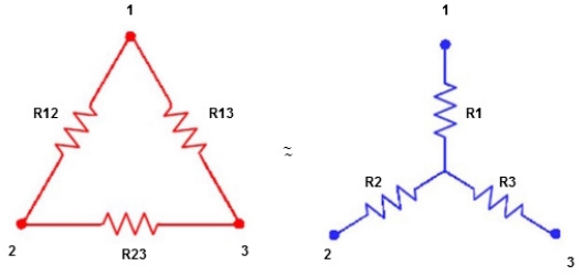
We know that (from delta to star conversion) R1 =
R2 =
R1 =
Multiply ① X ② L.H.S and R.H.S
R1 R2 =
Similarly multiply ② X ③
R2 R3 =
And ③ X①
R1 R3 =
Now add equation ④, ⑤, and ⑥ L.H.S and R.H.S
(Delta) Similarly R23 = R2+R3 +
R23 = R1+R2 + |
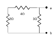
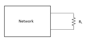
Where Rth is Thevenin’s equivalent resistance across a and b.
Maximum power is absorbed by ZL when Condition: Comparing real and imaginary parts OR Maximum power absorbed by ZL is
|
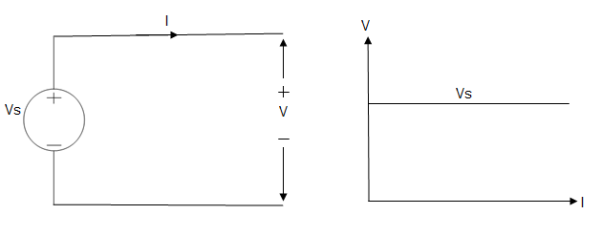
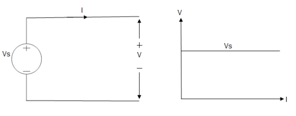
Ideal Voltage Source
Fig: Ideal Voltage Source
The graph represents the change in voltage of the voltage source with respect to time. It is constant at any instance of time. Voltage sources that have some amount of internal resistance are known as a practical voltage source. Due to this internal resistance, voltage drop takes place. If the internal resistance is high, less voltage will be provided to load and if the internal resistance is less, the voltage source will be closer to an ideal voltage source. A practical voltage source is thus denoted by a resistance in series which represents the internal resistance of source.
Practical Voltage source
Fig: Practical Voltage source
The graph represents the voltage of the voltage source with respect to time. It is not constant but it keeps on decreasing as the time passes. |
