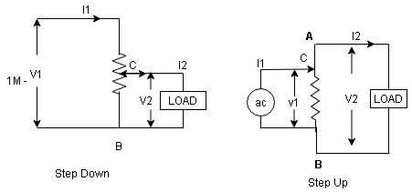
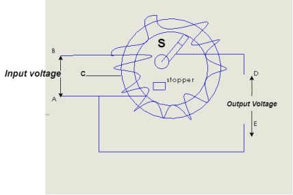
Auto Transformer An auto Transformer is a special type of transformer such that a part of the winding is common to both primary as well as secondary It has only One winding wended on a laminated magnetic core With the help of auto Transformer, the voltage can be stepped up and stepped down at any desired value
Fig A shows auto T/F as step down T/F variable terminal B C is connected to load and it acts as secondary wdg. The position of point C is called as topping point can be selected as per requirement Fig. B show auto T/F as step up T/F variable terminal B C is connected to supply side i.e. ac side and it acts as secondary winding The operating principle of auto Transformer is same as that of 2 winding Transformer
Advantages
Disadvantages: As low voltage and high voltage sides are not separate then there is always risk of electric shocks when use for high vtg. Applications Applications
|
There are 2 types of losses occurring in a transformer A) 1. Core loss or Iron loss B) 2. Copper loss
1 Hysteresis loss 2 reedy current loss
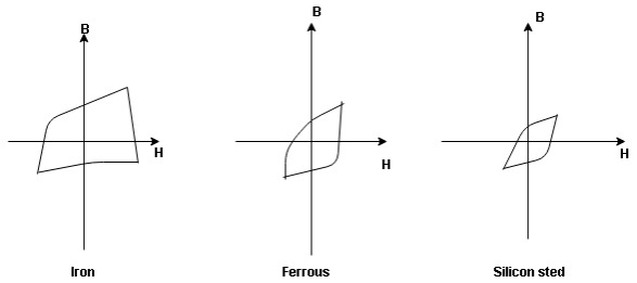
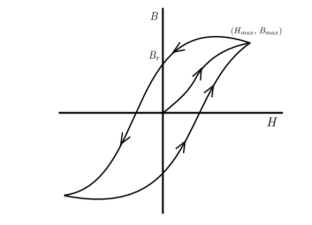
Hysteresis curve is the curve as loop which shows the properly of magnetic material to lag the flux density B behind the field Intensely H
Above is the 3 different loops (Hysteresis of 3 diff. Materials)
Hysteresis loss depends on fold factor PH = KH. Bm1.67 F Where KH = constant (Hyst) Bm = max Flux density F = Frequency
2. Reedy current loss : This loss is due to the flow of reedy (circular) current in the core caused by induced emf in core PE = Ke Bm2 f2 t2 v – watts Where Ke = reedy current const. t = thickness of core It can be reduced by using stacks of laminations instead of solid core B] Copper loss : PCU The Copper loss is due to resistance of the primary and secondary winding It is load dependent / current dependent loss As load on a transformer is variable (changing) Primary secondary Total C is loss = I12R12 + I22 R22 Copper loss depends upon load on T/F and is proportional to square of load current or KVA rating of transformer
F.L = full load
= (0.5)2 PCU F.L. Or PCu ( |
The excitation current I0‾ can be divided into two components Im‾ and Ii‾. Im‾ is its magnetizing component that creates mutual flux Φ‾, and Ii‾ is the core loss component that provides the loss associated with alternating of the flux. It can be represented as Here vector form is indicated by the negative (‾) symbol. Hence, the equivalent circuit of a practical transformer can be represented as shown in the figure below
Here, The impedance can now be referred to the primary side resulting in the following circuit:
Equivalent circuit referred to primary X l2’ = (N1/N2)2 X l2 |
An ideal transformer is one that has
Although an ideal transformer cannot be physically realized, yet its study provides a very powerful tool in the analysis of a practical transformer. In fact, practical transformers have properties that approach very close to an ideal transformer.
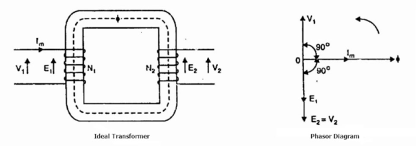
Consider an ideal transformer on no load i.e., the secondary is open-circuited as shown in the figure. Under such conditions, the primary is simply a coil of pure inductance. When an alternating voltage V₁ is applied to the primary, it draws a small magnetizing current Iₘ which lags behind the applied voltage by 90°. This alternating current Iₘ produces an alternating flux ϕ which is proportional to and in phase with it. The alternating flux ϕ links both the windings and induces e.m.f. E₁ in the primary and e.m.f. E₂ in the secondary. The primary e.m.f. E₁ is, at every instant, equal to and in opposition to V₁ (Lenz’s law). Both e.m.f.sE₁, and E₂ lag behind flux ϕ by 90°. However, their magnitudes depend upon the number of primary and secondary turns.
Phasor Diagram of Ideal Transformer The phasor diagram of an ideal transformer on no load is also shown above. Since flux ϕ is common to both the windings, it has been taken as the reference phasor. The primary e.m.f. E₁ and secondary e.m.f. E₂ lag behind the flux ϕ by 90°. Note that E₁ and E₂ are in phase. But E₁ is equal to V₁ and 180° out of phase with it. Practical Transformer A practical transformer differs from the ideal transformer in many respects. The practical transformer has,
1. Iron Losses Since the iron core is subjected to alternating flux, there occurs eddy current and hysteresis loss in it. These two losses together are known as iron losses or core losses. The iron losses depend upon the supply frequency, the maximum flux density in the core, volume of the core, etc. It may be noted that the magnitude of iron losses is quite small in a practical transformer. 2. Winding resistances Since the windings consist of copper conductors, it immediately follows that both primary and secondary will have winding resistance. The primary resistance R₁ and secondary resistance R₂ act in series with the respective windings as shown in the figure. When current flows through the windings, there will be power loss as well as a loss in voltage due to IR drop. This will affect the power factor and E₁ will be less than V₁ while V₂ will be less than E₂.
3. Leakage reactances Both primary and secondary currents produce flux. The flux ϕ which links both the windings is the useful flux and is called mutual flux. However, the primary current would produce some flux ϕ which would not link the secondary winding. Similarly, the secondary current would produce some flux ϕ that would not link the primary winding. The flux such as ϕ₁ or ϕ₂ which links only one winding is called leakage flux. The leakage flux paths are mainly through the air. The effect of these leakage fluxes would be the same as though inductive reactance were connected in series with each winding of the transformer that had no leakage flux as shown in the figure. In other words, the effect of primary leakage flux ϕ₁ is to introduce an inductive reactance X₁ in series with the primary winding as shown. Similarly, the secondary leakage flux ϕ₂ introduces an inductive reactance X₂ in series with the secondary winding. There will be no power loss due to leakage reactance. However, the presence of leakage reactance in the windings changes the power factor as well as there is voltage loss due to IX drop.
Note. It is because leakage flux paths are through the air of high reluctance and hence require considerable e.m.f. It may be noted that energy is conveyed from the primary winding to the secondary winding by mutual flux f which links both the windings. |
|
|
|
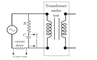
The rms voltage induced in a transformer is given by E = 4.44φmfN ---------(1) where, φm is maximum value of the flux in the core, f is operating frequency and N is number of turns in the coil. This flux in the coil is given by φm = BmAc ----------(2) where, Bm is the maximum flux density in core and Ac is the cross-sectional area of the core. So, we have E = 4.44BmAcfN -----------------(3) The value of induced voltage E is thus dependent upon Bm which can be setup in the core. From Biot-Savart’s law that a current carrying conductor produces magnetic field. “Magnetic field strength” H is proportional to the current which produces the field. From Ampere’s Circuital law, it can be proved that H is proportional to current I. If a current carrying coil produces magnetic flux which traverses an average length of l in complete flux path, then Hl = NI -------------------------------(4) In a magnetic circuit, this field is represented by magnetomotive force. It is analogous to the electromotive force in electrical circuit. This field is responsible to “set up” certain flux, which in turn gives rise to certain flux density B. The amount of flux which can be setup in a material is determined by an inherent property of the material, called as permeability, denoted by µ. B = µH --------------------------------(5) Let us consider materials used in the laminations of transformers. They are called ferromagnetic materials. A piece of ferromagnetic material is composed of several “domains”. In each domain, magnetic moments of all atoms are aligned in one direction. In general, the domains are randomly oriented. When external magnetic field H is applied to a material, all the domains align in a particular direction, setting up “net flux” in the material. Due to domain alignment B (i.e. the magnitude of B) increases. However, after a certain value of B, the slope of B − H curve starts reducing as shown in Fig. 1; O − S1 represents the linear region and S1 − S2 represents the “saturation region”.
From Faraday’s law, V = N dφ /dt B is directly proportional to flux φ. A signal proportional to B can be obtained by integrating the voltage signal. The voltage can be integrated approximately by using an RC circuit. The transfer function of the circuit is given by
The time constant τ = RC should be chosen such that, in frequency domain (1 + jωτ ) ≈ jωτ
Equation 4 tells that H is is proportional to current. The two signals can be given to two channels of a digital storage oscilloscope. B − H curve of the material can be seen. |
The efficiency of T/F is maximum when copper loss equates iron loss this is the condition for max efficiency ie Pi = PCU
Where KVA at max n given = Full load KVA |
