Given: number of lines per cm =4000 Grating element e+b = 1/4000 cm = 2.5 x 10⁻⁶m λ=500 nm Order n =1 (e+b) sinθ =nλ sinθ = nλ / (e+b) sinθ = 1 x 500 x 10-9 / 2.5 x 10⁻⁶ sinθ =0.2 θ =sin-1 0.2 θ = 11.5o |
The given data are Diameter of Newton’s 15th ring (D15) = 0.59 cm = 0.59×10⁻² m Diameter of Newton’s 5th ring (D5) = 0.336 cm = 0.336 × 10⁻² m Radius of curvature of lens (R) = 100 cm = 1 m Wave length of light (λ) = ? Here m is difference between rings = 15-5=10 λ = D2n+m - D2n / 4mR λ = (0.59×10⁻² )2- (0.336 × 10⁻²)2 / 4 x 10 x 1 λ = 0.3481 x10⁻⁴ – 0.112896 x10⁻⁴ / 40 λ =0.00588 x 10⁻⁴ m λ =5880 x 10-10 m λ =5880Å |
N = 1100 nm λ = 660 x 10-9 m n = 1 R = λ /dλ =Nn dλ = λ /Nn dλ = 660 x 10-9 / 1100 x 10-9 x 1 dλ = 0.6 x 10⁻⁹ m |
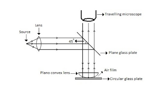
Newton’s Rings Newton’s Rings are the circular interference pattern first discovered by physicist Sir Isaac Newton in 1704. It is cosists of concentric bright and dark rings with the point of contact of lens and the glass plate as centre, The fringes obtained by interference of light waves by using the following arrangement When a Plano convex lens with large radius of curvature is placed on a plane glass plate such that its curved surface faces the glass plate, a wedge air film (of gradually increasing thickness) is formed between the lens and the glass plate. The thickness of the air film is zero at the point of contact and gradually increases away from the point of contact.
Figure Newton Ring Assembly If monochromatic (means light with single wavelength) light is allowed to fall normally on the lens from a source 'S', then two reflected rays R1 (reflected from upper surface of the film) and R2 (reflected from lower surface of the air film) interfere to produce circular interference pattern. This interference pattern has concentric alternate bright and dark rings around the point of contact. This pattern is observed through traveling microscope.
Mathematical analysis of Newton’s Ring
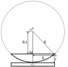
(OL)2 =(O’M)2-(ML)2 ……….(1) R2=(R-t)2 +rn2 R2=R2 +t2-2Rt +rn2 Radius is large as compared to the thickness so t2 is neglected as t2<< R2 R2=R2 +-2Rt +rn2 2Rt =rn2 Thickness of the film t =rn2 /2R ……….(2)
Theory of Fringes: The effective path difference between the two reflected rays R1 and R2 for a wedge shaped film from equation ∆ = 2μtcos(r+θ) +λ/2 ……….(3) If the light is incident normally on the lens, r = 0 and near to point of contact θ is small; Therefore near point of contact, (r+θ) approaches to 0 and cos(r+θ)=cos0=1 Therefore ∆ = 2μt+λ/2 ……….(4) Also At point of contact t = 0 therefore the effective path difference ∆ = λ/2 Which is odd multiple of λ/2 Therefore the Central fringe is dark. Bright Fringe : Condition of Maxima For the condition of maxima the effective path difference ∆ = ±nλ Using equation (4) ∆ = 2μt+λ/2 we have 2μt+λ/2= ±nλ 2μt = ± (2n-1)λ /2 ……….(5) Diameter of Bright Rings we know by equation (2) t =rn2 /2R substitute in equation (5) we have 2μ (rn2 /2R) = ± (2n-1)λ /2 rn2 = ± (2n-1)λR /2μ We know diameter D=2r and for nth fringe Dn=2rn so we have Dn2=± 2(2n-1)λR /μ Dn= The medium enclosed between the lens and glass plate is if air therefore, D= The diameter of bright ring is proportional to square root of odd natural numbers
Dark Fringe : Condition for Minima For the condition of minima, The effective path difference ∆ =± (2n+1)λ /2 2μt+λ/2 =± (2n+1)λ /2 2μt= ±nλ ……….(7) it is clear that for particular dark or bright fringe t should be constant. Every fringe is the locus of points having equal thickness. Hence the fringes are circular in shape. Diameter of Dark Rings we know by equation (2) t =rn2 /2R substitute in equation (7) we have 2μ (rn2 /2R ) = nλ rn2 = nλR/ μ We know diameter D=2r and for nth fringe Dn=2rn so we have Dn2= 4nλR/ μ Dn= The medium enclosed between the lens and glass plate is if air therefore, Dn= The diameter of dark ring is proportional to square root of natural numbers |
The given data are Wave length of light (λ) = 5900 Å= 5900 × 10–10 m Diameter of 10th Newton’s dark ring (D10) = 0.5 cm = 0.5 × 10⁻² m Radius of curvature of lens (R) = ? Formula is D2n = 4nλR R= D2n /4nλ R= (0.5 × 10⁻²)2 /4x 10 x 5900 × 10–10 R= 0.25 x10⁻⁴ /236x10-7 R=1.059m |
Spacing between Fringes The Newton’s rings are not equally spaced because the diameter of ring does not increase in the same proportion as the order of ring and rings get closer and closer as ‘n’ increases. For example the diameter of dark ring is given by Dn= D3 - D2 = D7 – D6 = D10– D9 = From above result we conclude that the fringe width reduces with increase in n. |
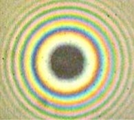
Newton’s Ring with White Light If the monochromatic source is replaced by the white light, dark and bright fringes are not produced. Because the diameter of the rings depends upon wavelength and it is proportional to the square root of wavelength. If If the monochromatic source is replaced by the white light superposition of rings take place due to different wavelength. Few coloured rings are seen around dark centre later illumination is seen in the field of view. As shown in below figure.
|
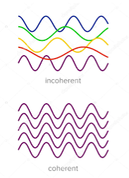
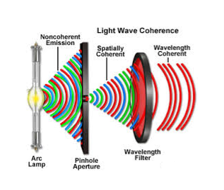
Two sources are said to be coherent when the waves emitted from them have the same frequency and constant phase difference. Interference from such waves happen all the time, the randomly phased light waves constantly produce bright and dark fringes at every point. But, we cannot see them since they occur randomly. A point that has a dark fringe at one moment may have a bright fringe at the next moment. This cancels out the effect of the interference effect, and we see only an average brightness value. The interference is not said to be sustained since we cannot observe it.
Definition:- A predictable correlation of the amplitude and phase at any one point with other point is called coherence.
Two waves are said to be coherent, the waves must have
In case of convectional light, the property of coherence exhibits between a source and its virtual source where as in case of laser the property coherence exists between any two of more light waves.
There are two types of coherence i) Temporal coherence ii) Spatial coherence
Temporal coherence (or longitudinal coherence):- The predictable correlation of amplitude and phase at one point on the wave train w .r. t another point on the same wave train, then the wave is said to be temporal coherence
To understand this, let us consider two points P1 and P2 on the same wave train, which is continuous as in shown in figure.
Suppose the phase and amplitude at any one point is known, then we can easily calculate the amplitude and phase for any other point on the same wave train by using the wave equation y= a sin ( Where ‘a’ is the amplitude of the wave and ‘x’ is the displacement of the wave at any instant of time‘t’.
Spatial coherence (or transverse coherence) The predictable correlation of amplitude and phase at one point on the wave train w. r .t another point on a second wave, then the waves are said to be spatial coherence (or transverse coherence)
|
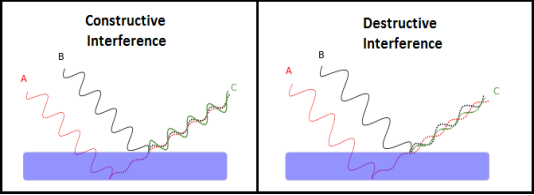
Interference in light waves occurs whenever two or more waves overlap at a given point. TYPES OF INTERFERENCE Interference of light waves can be either constructive interference or destructive interference.
We know that the superposition of two mechanical waves can be constructive or destructive. In constructive interference, the amplitude of the resultant wave at a given position or time is greater than that of either individual wave, whereas in destructive interference, the resultant amplitude is less than that of either individual wave. Light waves also interfere with each other. Fundamentally, all interference associated with light waves arises when the electromagnetic fields that constitute the individual waves combine. If two light bulbs are placed side by side, no interference effects are observed because the light waves from one bulb are emitted independently of those from the other bulb. The emissions from the two light bulbs do not maintain a constant phase relationship with each other over time. Light waves from an ordinary source such as a light bulb undergo random phase changes in time intervals less than a nanosecond. Therefore, the conditions for constructive interference, destructive interference, or some intermediate state are maintained only for such short time intervals. Because the eye cannot follow such rapid changes, no interference effects are observed. Such light sources are said to be incoherent. |
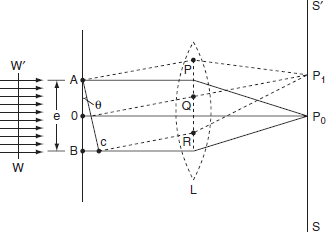
The adjacent figure represents a narrow slit AB of width ‘e’. Let a plane wavefront of monochromatic light of wavelength ' The intensity at the point P1 is either minimum or maximum and depends upon the path difference between the secondary waves originating from the corresponding points of the wavefront.
Theory: In order to find out the intensity at P1, draw a perpendicular AC on BR. The path difference between secondary wavelets from A and B in direction θ is BC i.e,
So, the phase difference,
Let us consider that the width of the slit is divided into ‘n’ equal parts and the amplitude of the wave from each part is ‘a’. So, the phase difference between two consecutive points
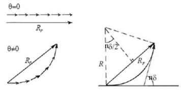
Then the resultant amplitude R is calculated by using the method of vector addition of amplitudes
The resultant amplitude of n number of waves having same amplitude 'a' and having common phase difference of '
Substituting the value of R = a Substituting As R = n and na = A Therefore R =A Therefore, the Intensity is given by I =R2 = A2 Case (i): Principal Maximum: Eqn (4) takes maximum value for
sinθ = 0 or θ=0 The condition The condition θ=0 means that this maximum is formed by the secondary wavelets which travel normally to the slit along OP0 and focus at P0. This maximum is known as “Principal maximum”. Intensity of Principal maxima
Therefore Imax = R2max = A2 Case (ii): Minimum Intensity positions: Equation (3) takes minimum values for sin
In the above equation (6) n = 0 is not applicable because corresponds to principal maximum. Therefore, the positions according to equation (6) are on either side of the principal maximum. Case (iii): Secondary maximum: In addition to principal maximum at
A2
Because
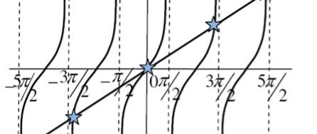
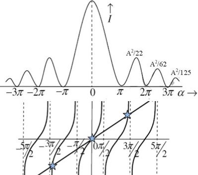
The values of ' The points of intersection of the two curves gives the values of The points of intersections are
But
and so on. From the above expressions, Imax, I1, I2,I3… it is evident that most of the incident light is concentrated at the principal maximum. INTENSITY DISTRIBUTION GRAPH A graph showing the variation of intensity with '
|
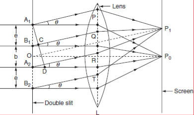
The double slits have been represented as A1B1 and A2B2 in Figure the slits are narrow and rectangular in shape. The planes of the slits are perpendicular to plane of the paper. Let the width of both the slits be equal and it is ‘e’ and they are separated by opaque length ‘d’. A monochromatic plane wave front of wave length ‘λ’ is incident normally on both the slits.
THEORY: Light is made incident on arrangement of double slit. The secondary wavelets travelling in the direction of OP0 are brought to focus at P0 on the screen SS′ by using a converging lens L. P0 corresponds to the position of the central bright maximum. The intensity distribution on the screen is the combined effect of interference of diffracted secondary waves from the slits. The diffracted intensity on the screen is very large along the direction of incident beam [i.e along OP0]. Hence it is maximum at P0. This is known as principal maximum of zero order. The intensity at point P1 on the screen is obtained by applying the Fraunhofer diffraction theory at single slit and interference of diffracted waves from the two slits. The diffracted wave amplitude due to single slit at an angle θ with respect to incident beam is A This phase difference can be estimated as follows: Draw a normal from A1 to B1Q. Now, B1C is the path difference between the diffracted waves at an angle ‘θ’ at the slit A1B1. From the triangle A1B1C
The corresponding phase difference
Or The diffracted wave amplitudes, In the triangle or the path difference A2D = A1A2 sin θ = (e + b) sin θ The corresponding phase difference
Applying the theory of interference on the wave amplitudes
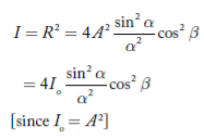
The intensity at P1 is
Equation (4) represents the intensity distribution on the screen. The intensity at any point on the screen depends on α and β. The intensity of central maximum is 4Io. The intensity distribution at different points on the screen can be explained in terms of path difference between the incident and diffracted rays as follows. In equation (4) the term cos2β corresponds to interference and Interference maxima and minima: If the path difference A2D = (e + b) sinθn = ± nλ where n = 1, 2, 3… then ‘θn’ gives the directions of the maxima due to interference of light waves coming from the two slits. The ± sign indicates maxima on both sides with respect to the central maximum. On the other hand if the path difference is odd multiples of λ/2 i.e.,
then θn gives the directions of minima due to interference of the secondary waves from the two slits on both sides with respect to central maximum. Diffraction maxima and minima: If the path difference B1C = e sinθn = ± nλ, where n = 1, 2, 3… then θn gives the directions of diffraction minima. The ± sign indicates minima on both sides with respect to central maximum. For diffraction maxima
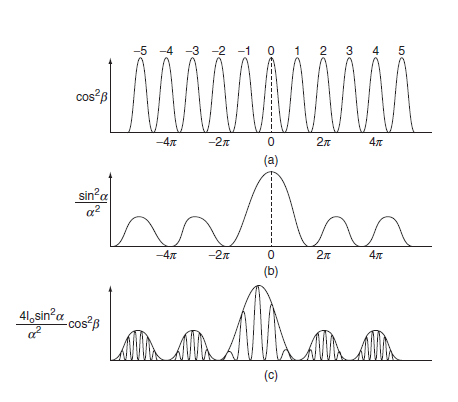
is the condition. The ± sign indicates maxima on both sides with respect to central maximum. The intensity distribution on the screen due to double slit diffraction is shown in Figure. Figure(a) represents the graph for interference term, Figure (b) shows the graph for diffraction term and Figure (c) represents the resultant distribution. Based on the relative values of e and b certain orders of interference maxima are missing in the resultant pattern. The direction of interference maxima are given as (e + b) sin θn = nλ where n = 1, 2, 3, ….. and the directions of diffraction minima are given as e sin θm = mλ where m = 1, 2, 3, … Figure: Intensity distribution due to diffraction at double slit. For some values of θn, the values of e and b are satisfied such that at these positions the interference maxima and the diffraction minima are formed. The combined effect results in missing of certain orders of interference maxima. Now we see certain values of e and b for which interference maxima are missing. (i) Let e = b Then, 2esinθn = nλ and esinθm = mλ If m = 1, 2, 3 … then n = 2, 4, 6… i.e., the interference orders 2, 4, 6 … missed in the diffraction pattern (ii) If 2e = b Then 3e sin θm = nλ and e sin θm = mλ if μ = 1, 2, 3… Then n = 3, 6, 9… i.e the interference orders 3, 6, 9… are missed in the diffraction pattern (iii) if e + b = e i.e b = 0 the two slits are joined. So, the diffraction pattern is due to a single slit of width 2e. |
It may be possible that while the first order spectra is clearly visible, second order may be not be visible at all and the third order may again be visible. This happens when for a given angle of diffraction θ, the path difference between the diffracted rays from the two extreme ends of one slit is equal to an integral multiple of λ. Suppose the path difference is λ, then each slit can be considered to be made up of two halves, the path difference between the secondary waves from the corresponding points in the two halves will be λ / 2. Now they will cancel one another resulting zero intensity. Thus the mining of single slit pattern are obtained in the direction given by. asinθ= mλ …………(1) Where m = 1, 2, 3, excluding zero but the condition for nth order principles maximum in the grating spectrum is (a + b) sinθ= nλ …………… (2) If the two conditions given by equation (2) are simultaneously satisfied then the direction in which the grating spectrum should give us a maximum every slit by itself will produce darkness in that direction and hence the most favourable phase for reinforcement will not be able to produce an illumination i.e. The resultant intensity will be zero and hence the absent spectrum. Therefore dividing equation (2) by equation (1) ((a+ b) sinθ) /a sinθ=n/ m (a+ b) /a =n/m This is the condition for the absent spectra in the diffraction pattern If a= b i.e., the width of transparent portion is equal to the width of opaque portion then from equation (3) n = 2m i.e., 2nd, 4th, 6th etc., orders of the spectra will be absent corresponds to the minima due to single slit given by m = 1, 2, 3 etc. b = 2a …………..(3) n=3m i.e., 3rd, 6th, 9th etc., order of the spectra will be absent corresponding to a minima due to a single slit given by m = 1, 2, 3 etc. |
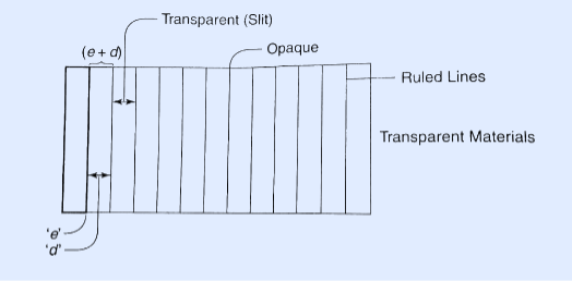
A set of large number of parallel slits of same width and separated by opaque spaces is known as diffraction grating. Diffraction gratings are much more effective than prisms for dispersing light of different wavelengths so they are used almost exclusively in instruments designed to detect and identify characteristic spectral lines. There is nothing mysterious about these devices. Fraunhofer used the first grating consisting of a large number of parallel wires placed side by side very closely at regular separation. Now the gratings are constructed by ruling the equidistance parallel lines on a transparent material such as glass with fine diamond point. The ruled lines are opaque to light while the space between the two lines is transparent to light and act as a slit.
Let ‘e’ be the width of line and ‘d’ be the width of the slit. Then (e + d) is known as grating element. If N is the number of lines per inch on the grating then (𝑒+𝑑)=1𝑖𝑐ℎ=2.54𝑐𝑚 (𝑒+𝑑)=2.54𝑐𝑚/𝑁 Commercial gratings are produced by taking the cost of actual grating on a transparent film like that of cellulose acetate. Solution of cellulose acetate is poured on a ruled surface and allowed to dry to form a thin film, detachable from the surface. This film of grating is kept between the two glass plates. |
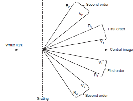
The principle maxima in a grating are formed in direction given by (e + d)sinθ =nλ where (e + d ) is the grating element, ‘n’ the order of the maxima and 1) For a given wavelength 2) For white light and for a particular order n, the light of different wavelengths will be diffracted in different directions. The longer the wavelength, greater is the angle of diffraction. So in each order, we will get the spectra having as many lines as the wavelength in the light source. At centre (n = 0, zero order) Similarly the principal maxima of all wavelengths corresponding to n = 1 will form the first order spectrum, the principal maxima of all wavelengths corresponding to n = 2, will form the second order spectrum and so on.
From this we conclude that Important characteristics of grating spectra: 1) Spectra of different orders are situated symmetrically on both sides of zero order. 2) Spectral lines are almost straight and quite sharp. 3) Spectral colours are in the order from Violet to Red. 4) Spectral lines are more dispersed as we go to higher orders. 5) Most of the incident intensity goes to zero order and rest is distributed among the other orders. |
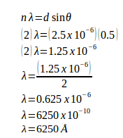
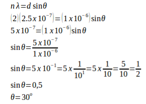
The distance between slits (d) = 1 / (4000 slits / cm) = 0.00025 cm = 2.5 x 10⁻⁴ cm = 2.5 x 10⁻⁶ meters Order (n) = 2 Sin 30o = 0.5 1 Å = 10-10 m Wavelength of the light (λ) =?
|
Given The distance between slits (d) = 1 / (10,000 slits / cm) = 0.0001 cm = 1 x 10⁻⁴ cm = 1 x 10⁻⁶ m Order (n) = 2 Wavelength (λ) = 2.5 x 10⁻⁷ m Angle (θ)
|
Wavelength (λ) = 500.10-9 m = 5.10-7 m θ = 30o n = 2 Distance between slits: d sin θ = n λ d (sin 30o) = (2)(5.10-7) d (0.5) = 10.10-7 d = (10.10-7) / 0.5 d = 20.10-7 d = 2.10-6 m Number of slits per centimetre: x = 1 / d x = 1 / 2.10-6 m x = 0.5.106 / 1 m x = 0.5.106 / 102 cm x = 0.5.104 cm x = 5.103 /cm x = 5000 /cm |
Wavelength (λ) = 500.10-9 m = 5.10-7 m θ = 30o n = 4 Distance between slits: d sin θ = n λ d (sin 30o) = (4)(5.10-7) d (0.5) = 20.10-7 d = (20.10-7) / 0.5 d = 40.10-7 d = 4.10-6 m Number of slits per centimetre: x = 1 / 4.10-6 m x = 0.25.106 / m x = 0.25.106 / 102 cm x = 0.25.104 / cm x = 25.102 per cm x = 2500 per cm |
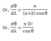
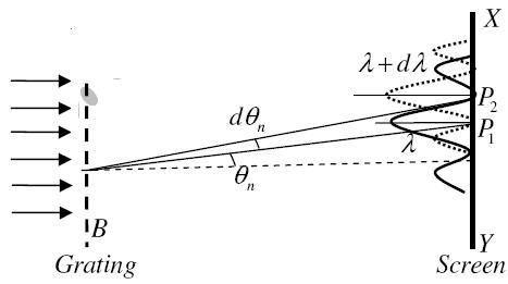
Dispersive power of a grating is defined as the ratio of the difference in the angle of diffraction of any two neighbouring spectral lines to the difference in the wavelength between the two spectral lines. Or It can also be defined as the diffraction in the angle of diffraction per unit change in wavelength. The diffraction of the nth order principal maximum for a wavelength λ is given by the equation, a + b is constant and n is constant in a given order.
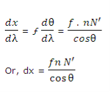
In equation (2) dθ/dλ is the dispersive power, n is the order of the spectrum, N’ is the number of lines per cm of the grating surface and θ is the angle of diffraction for the nth order principal maximum of wavelength λ. From equation (2), it is clear, that the dispersive power of the grating is directly proportional to the number of lines per cm and inversely proportional to cos θ. Thus, the angular spacing of any two spectral lines is double in the second order spectrum in comparison to the first order. Secondly, the angular dispersion of the lines is more with a grating having larger number of lines per cm. thirdly, the angular dispersion is minimum when θ = 0. If the value of θ is not large the value of cosθ can be taken as unity approximately and the influence of the factor cosθ in the equation (2) can be neglected. Neglecting the influence of cosθ, it is clear that the angular dispersion of any two spectral lines (in a particular order) is directly proportional to the difference in wavelength between the two spectral lines. A spectrum of this type is called a normal spectrum. If the linear spacing of two spectral lines of wavelength λ and λ + dλ is dx in the focal plane of the telescope objective or the photographic plate, then, dx = fdθ
|
Limit of Resolution: The minimum distance between two points on the object so that their images (as produced by the optical instrument) are just seen as separate from each other is called limit of resolution of the optical instrument. Statement: Two sources are resolvable by an optical instrument when the central maximum of one diffraction pattern falls over the first minimum of the other diffraction pattern and vice versa. Let us consider the resolution of two wavelengths by a grating. When the difference in wavelengths is smaller and such that the central maximum of the wavelength coincides with the first minimum of the other as shown in figure, then the resultant intensity curve is as shown by the thick curve. The curve shows a distinct dip in the middle of two central maxima. Thus the two wavelengths can be distinguished from one another and according to Rayleigh they are said to be “Just Resolved”. If the difference in wavelengths is such that their principal maxima are separately visible, then there is a distinct point of zero intensity in between the two wavelengths. Hence according to Rayleigh they are said to be “Resolved”. When the difference in wavelengths is so small that the central maxima corresponding to two wavelengths come still closer as shown in figure, then the resultant intensity curve is quite smooth without any dip. This curve is as if there is only one wavelength somewhat bigger and stronger. Hence according to Rayleigh the two wavelengths are “Not Resolved”. Thus the two spectral lines can be resolved only up to a certain limit expressed by Rayleigh Criterion.
|
It is defined as the capacity of a grating to form separate diffraction maxima of two wavelengths which are very close to each other It is measured by λ/dλ where dλ is the smallest difference in two wavelengths which are just resolvable by grating and λ is the wavelength of either of them or mean wavelength.
Let AB represent the surface of a plane transmission grating having grating element (e+d) and N total number of slits. Let a beam of light having two wavelengths by λ and dλ is normally incident on the grating. Let P1 is nth primary maximum of a spectral line of wavelength λ at an angle of diffraction According to Rayleigh criterion, the two wavelengths will be resolved if the principal maximum λ+dλ of nth order in a direction θ+dθ falls over the first minimum of nth order in the same direction θ+dθ. Let us consider the first minimum of l of nth order in the direction θ+dθ as below. The principal maximum of (e+d)sinθ =nλ ………………(1) The equation of minima is N(e+d)sinθ = mλ ………………(2) Where m takes all integers except 0, N, 2N, …, nN, because for these values of m, the condition for maxima is satisfied. Thus first minimum adjacent to nth principal maximum in the direction θ+dθ can be obtained by substituting the value of ‘m’ as (nN+1). Therefore, the first minimum in the direction of θ+dθ is given by N(e+d)sin(θ+dθ) = (nN+1)λ (e+d)sin(θ+dθ) = (n+ The principal maximum of λ+dλ in direction θ+dθ is given by (e+d)sin(θ+dθ) = n(λ+dλ) ………………(4) Dividing eqn(3) by equation (4), we get (n+ nλ +
Resolving Power = Thus the resolving power is directly proportional to (i) The order of the spectrum ‘n’ (ii) The total number of lines on the grating ‘N’. |
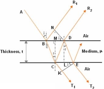
Consider a thin film of uniform thickness ‘t’ and refractive index μ bounded between air. Let us consider monochromatic ray AB is made incident on the film, at B part of ray is reflected (R1) and a part is refracted along BC. At C The beam BC again suffer partial reflection and partial refraction; the reflected beam CD moves again suffer partial reflection and partial refraction at D. The refracted beam R2 moves in air. These two reflected rays R1 and R2 interfere to produce interference pattern.
The optical path difference between the two reflected rays
In ΔBDN, sin i = BN / BD and BC = CD as ΔBMC ≡ ΔMCD, therefore
In ΔBMC, cos r = t /BC, therefore
In ΔBMC, tan r = BM / t , therefore
Correction on account of phase change at reflection: When a beam is reflected from a denser medium (ray R1 at B), a path change of λ/2 occur for the ray.
Therefore the true path difference is Condition of Maxima (Bright Fringe) Maxima occur when path difference
Condition for Minima (Dark Fringe) Minima occur when path difference
INTERFERENCE IN THIN FILM (TRANSMITTED RAYS) The optical path difference between transmitted rays T1 and T2 will be This path difference is calculated in the same way as above to get
Condition of Maxima (Bright Fringe) Maxima occur when path difference,
Condition for Minima (Dark Fringe) Minima occur when path difference,
|
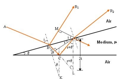
The wedge shaped film has a thin film of varying thickness, having thickness zero at one end and increases at the other. The angle of wedge is θ.Wedge shaped film is one whose surface are inclined at an angle θ of refractive index μ bounded by non-uniform thickness.
The optical path difference between the two reflected rays R1 and R2 will be
From the geometry
As in ΔBMD;
Or Thus
As in ΔNDL
Correction on account of phase change at reflection: when a beam is reflected from a denser medium (ray R1 at B), a path change of Therefore the true path difference is
Condition of Maxima (Bright Fringe) Maxima occur when path difference,
Condition for Minima (Dark Fringe) Minima occur when path difference
|
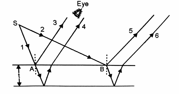
The interference in thin films can be observed without using a lens, because the eye lens can form a real image of the interference pattern on the retina. With the point source, we get different rays which are incident on the film at different angles as shown in figure. The incident ray SA, gives rise to the reflected rays 3 and 4, which go parallel to each other and on entering the eye will produce reference. The incident ray SB gives rise to the reflected rays 5 and 6, which also go parallel to each other and may interfere on the retina of the eye. Since, the size of the eye lens is very very small, therefore we are able to see only a very small portion of the interference pattern. To see the interference in different parts of the film, the eye needs to be moved sideways.
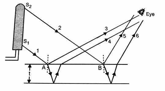
Thus a point source is not suitable for observing the interference of light on whole of the film simultaneously. In the case of interference in thin film, the narrow source limits the visibility of film. To observe the interference of light on whole of the film simultaneously we need to use an extended source of light.
As shown in the figure from the extended source we have two incident rays S2B and S1A respectively and the reflected rays due to them are reaching the eye. In fact, every part of the film will receive light from some part of the source so that the reflected rays will reach the eye. As a result, the interference pattern can be observed on whole of the film simultaneously. |
