Unit – 4
Measurements and Control System
Q1) Explain the concept of measurement
A1) Measurement:
The process or act of measurement consists of obtaining a quantitative comparison between a predefined standard and a measurand. Measurand is used to designate the particular phhysical parameter being observed and quantified: this is the input quantity of the measuring process.
Measurement provides a comparison between what was intended and what was actually achieved. Measurement is also a fundamental element of any control process. The concept of control requires the measured discrepancy between the actual and the desired performances. The controlling portion of the system must know the magnitude and direction of the difference in order to react intelligently. Temperature, flows, pressure and vibrational amplitudes must be constantly monitored by measurement to ensure proper performance of the system.
To be useful, measurement must be reliable. Having incorrect information is potentially more damaging than having no information.
The input to a measuring system is known as measurand, the output is called measurement.

Figure. Fundamental measuring process.
Fundamental methods of measurement:
There are two basic methods of measurement
1. Direct comparison with either a primary or a secondary standard and
2. Indirect comparison through the use of a calibrated system.
Direct and Indirect measurements:
Measurement is a process of comparison of the physical quantity with a reference standard.
1. Direct Measurements:
The value of the physical parameter (measurand) is determined by comparing it directly with reference standards. The physical quantities like mass, length and time are measured by direct comparison.
2. Indirect Measurement:
There are a number of quantities that do not make use of direct instruments for their measurement. Some interpretations or tests need to be conducted to comment on their measurement levels. All the methods and techniques that make use of logs, charts, readouts and interpretations of data and analysis fall under the category of indirect measurement methods. An indirect measurement system comprises of instruments such as transducers, sensors, data readers and interpreter which are integrated in a way that the entire measuring system senses, analyses and converts data into analogues output in the form of charts and logs.
Standard:
A physical representation of a unit of measurement. A piece of equipment having a known measure of physical quantity.
Q2) Define the term Error in measurements
A2) Types of Errors in Measurement
The error may arise from the different source and are usually classified into the following types. These types are
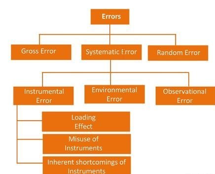
Their types are explained below in details.
1. Gross Errors
The gross error occurs because of the human mistakes. For examples consider the person using the instruments takes the wrong reading, or they can record the incorrect data. Such type of error comes under the gross error. The gross error can only be avoided by taking the reading carefully.
For example – The experimenter reads the 31.5ºC reading while the actual reading is 21.5Cº. This happens because of the oversights. The experimenter takes the wrong reading and because of which the error occurs in the measurement.
Such type of error is very common in the measurement. The complete elimination of such type of error is not possible. Some of the gross error easily detected by the experimenter but some of them are difficult to find. Two methods can remove the gross error.
Two methods can remove the gross error. These methods are
2. Systematic Errors
The systematic errors are mainly classified into three categories.
2 (i) Instrumental Errors
These errors mainly arise due to the three main reasons.
(a) Inherent Shortcomings of Instruments – Such types of errors are inbuilt in instruments because of their mechanical structure. They may be due to manufacturing, calibration or operation of the device. These errors may cause the error to read too low or too high.
For example – If the instrument uses the weak spring, then it gives the high value of measuring quantity. The error occurs in the instrument because of the friction or hysteresis loss.
(b) Misuse of Instrument – The error occurs in the instrument because of the fault of the operator. A good instrument used in an unintelligent way may give an enormous result.
For example – the misuse of the instrument may cause the failure to adjust the zero of instruments, poor initial adjustment, using lead to too high resistance. These improper practices may not cause permanent damage to the instrument, but all the same, they cause errors.
(c) Loading Effect – It is the most common type of error which is caused by the instrument in measurement work. For example, when the voltmeter is connected to the high resistance circuit it gives a misleading reading, and when it is connected to the low resistance circuit, it gives the dependable reading. This means the voltmeter has a loading effect on the circuit.
The error caused by the loading effect can be overcome by using the meters intelligently. For example, when measuring a low resistance by the ammeter-voltmeter method, a voltmeter having a very high value of resistance should be used.
2 (ii) Environmental Errors
These errors are due to the external condition of the measuring devices. Such types of errors mainly occur due to the effect of temperature, pressure, humidity, dust, vibration or because of the magnetic or electrostatic field. The corrective measures employed to eliminate or to reduce these undesirable effects are
2 (iii) Observational Errors
Such types of errors are due to the wrong observation of the reading. There are many sources of observational error. For example, the pointer of a voltmeter resets slightly above the surface of the scale. Thus, an error occurs (because of parallax) unless the line of vision of the observer is exactly above the pointer. To minimise the parallax error highly accurate meters are provided with mirrored scales.
3. Random Errors
The error which is caused by the sudden change in the atmospheric condition, such type of error is called random error. These types of error remain even after the removal of the systematic error. Hence such type of error is also called residual error.
Q3) Define the term Calibration
A3) Calibration of the measuring instrument is the process in which the readings obtained from the instrument are compared with the sub-standards in the laboratory at several points along the scale of the instrument. As per the results obtained from the readings obtained of the instrument and the sub-standards, the curve is plotted. If the instrument is accurate there will be matching of the scales of the instrument and the sub-standard. If there is deviation of the measured value from the instrument against the standard value, the instrument is calibrated to give the correct values.
Q4) Explain the term Measurements of pressure
A4) Pressure is defined as force per unit area that a fluid exerts on its surroundings. Pressure, P, is a function of force, F, and area, A:
P = F/A
The SI unit for pressure is the pascal (N/m2), but other common units of pressure include pounds per square inch (psi), atmospheres (atm), bars, inches of mercury (in. Hg), millimeters of mercury (mm Hg), and torr.
A pressure measurement can be described as either static or dynamic. The pressure in cases with no motion is static pressure. Examples of static pressure include the pressure of the air inside a balloon or water inside a basin. Often, the motion of a fluid changes the force applied to its surroundings. For example, say the pressure of water in a hose with the nozzle closed is 40 pounds per square inch (force per unit area). If you open the nozzle, the pressure drops to a lower value as you pour out water. A thorough pressure measurement must note the circumstances under which it is made. Many factors including flow, compressibility of the fluid, and external forces can affect pressure.
Q5) What are the different type of measurement of pressure method.
A5)

Absolute Pressure
The absolute measurement method is relative to 0 Pa, the static pressure in a vacuum. The pressure being measured is acted upon by atmospheric pressure in addition to the pressure of interest. Therefore, absolute pressure measurement includes the effects of atmospheric pressure. This type of measurement is well-suited for atmospheric pressures such as those used in altimeters or vacuum pressures. Often, the abbreviations Paa (Pascal’s absolute) or psia (pounds per square inch absolute) are used to describe absolute pressure.
Gauge Pressure
Gauge pressure is measured relative to ambient atmospheric pressure. This means that both the reference and the pressure of interest are acted upon by atmospheric pressures. Therefore, gauge pressure measurement excludes the effects of atmospheric pressure. These types of measurements include tire pressure and blood pressure measurements. Similar to absolute pressure, the abbreviations Pag (Pascal’s gauge) or psig (pounds per square inch gauge) are used to describe gauge pressure.
Differential Pressure
Differential pressure is similar to gauge pressure; however, the reference is another pressure point in the system rather than the ambient atmospheric pressure. You can use this method to maintain relative pressure between two vessels such as a compressor tank and an associated feed line. Also, the abbreviations Pad (Pascal’s differential) or PSID (pounds per square inch differential) are used to describe differential pressure
Q6) Define the different Temperature Measurement
A6) Temperature Measurement
Temperature is the measure of heat in the body. Temperature characterizes the body as hot or cold. The SI unit used to measure the temperature in Kelvin(K). The other scales used to measure the temperature are Celsius or Fahrenheit. The instrument which is used for measuring temperature is a thermometer.
Devices for Temperature Measurement
Thermometer
A thermometer is an instrument which is used for measuring temperature of a body. The first invention to measure the temperature was by Galileo. He invented the rudimentary water thermometer in 1593. He named this device “Thermoscope”. This instrument was ineffective because water froze at low temperature.
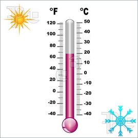
In 1974, Gabriel Fahrenheit invented the mercury thermometer. A mercury thermometer consists of a long, narrow and uniform glass tube called the stem. The scales on which temperature is measured are marked on the stem. There is a small bulb at the end of the stem which contains mercury in it. A capillary tube is there inside glass stem in which mercury gets expanded when a thermometer comes in contact with a hot body.
Mercury is toxic and it is difficult to dispose of it when the thermometer breaks. Nowadays, digital thermometers have come into play which doesn’t contain mercury. The two commonly used thermometers are Clinical thermometers and Laboratory thermometers.
Clinical Thermometer
These thermometers are used in homes, clinics, and hospitals. These thermometers contain kink which prevents mercury to go back when it is taken out of patient’s mouth so that temperature can be noted down easily. There are two temperature scales on either side of mercury thread, one is Celsius scale and other is Fahrenheit scale.
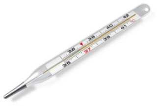
It can give temperature range from a minimum of 35°C or 94°F to the maximum of 42°C or 108°F. Fahrenheit scale is more sensitive than Celsius scale. Thus, the temperature is measured in Fahrenheit(°F).
Laboratory Thermometer
Laboratory thermometers can be used to notice the temperature in school labs or other labs for scientific research purposes. These are also used in industries to measure the temperature of solutions or instruments.
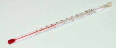
The stem, as well as bulb of laboratory thermometer, is longer when compared to the clinical thermometer. There is no kink in laboratory thermometer. It has only Celsius scale. It can measure temperature from -10°C to 110°C.
Q7) Describe the Mass flow rate
A7) In physics and engineering, mass flow rate is the mass of a substance which passes per unit of time. Its unit is kilogram per second in SI units, and slug per second or pound per second in US customary units. The common symbol is (ṁ, pronounced "m-dot"), although sometimes μ (Greek lowercase mu) is used.
Sometimes, mass flow rate is termed mass flux or mass current, see for example Schaum's Outline of Fluid Mechanics.[1] In this article, the (more intuitive) definition is used.
Mass flow rate is defined by the limit

i.e., the flow of mass m through a surface per unit time t.
The over dot on the m is Newton's notation for a time derivative. Since mass is a scalar quantity, the mass flow rate (the time derivative of mass) is also a scalar quantity. The change in mass is the amount that flows after crossing the boundary for some time duration, not the initial amount of mass at the boundary minus the final amount at the boundary, since the change in mass flowing through the area would be zero for steady flow.
Q8) Describe the term Force and torques
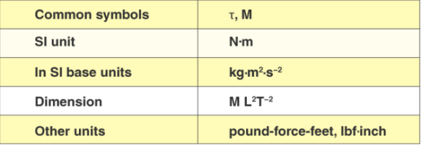
A8) Torque is the measure of the force that can cause an object to rotate about an axis. Force is what causes an object to accelerate in linear kinematics. Similarly, torque is what causes an angular acceleration. Hence, torque can be defined as the rotational equivalent of linear force. The point where the object rotates is called the axis of rotation. In physics, torque is simply the tendency of a force to turn or twist. Different terminologies such as moment or moment of force are interchangeably used to describe torque.
Force
Push or pull of an object is considered a force. Push and pull come from the objects interacting with one another. Terms like stretch and squeeze can also be used to denote force.
In Physics, force is defined as:
The push or pull on an object with mass that causes it to change its velocity.
Force is an external agent capable of changing the state of rest or motion of a particular body. It has a magnitude and a direction. The direction towards which the force is applied is known as the direction of the force and the application of force is the point where force is applied.
The Force can be measured using a spring balance. The SI unit of force is Newton(N).
Common symbols: | F→, F |
SI unit: | Newton |
In SI base units: | kg·m/s2 |
Other units: | dyne, poundal, pound-force, kip, kilo pond |
Derivations from other quantities: | F = m a |
Dimension: | LMT-2 |
Q9) Explain the Introduction to Control Systems
A9) A control system is a set of mechanical or electronic devices which control the other devices. In control system behaviours of the system is desired by differential equations.

Fig: Block diagram for closed loop control system
The above figure shows a feedback system with a control system. The components of control system are:
i) The actuator takes the signal transforms it accordingly and causes some action.
ii) Sensors are used to measure continuous and discrete process variables.
iii) Controllers are those elements which adjust the actuators in response to the measurement.
Q10) Explain the control system
A10) A control system is a system, which provides the desired response by controlling the output. The following figure shows the simple block diagram of a control system.

Here, the control system is represented by a single block. Since, the output is controlled by varying input, the control system got this name. We will vary this input with some mechanism. In the next section on open loop and closed loop control systems, we will study in detail about the blocks inside the control system and how to vary this input in order to get the desired response.
Examples − Traffic lights control system, washing machine
Traffic lights control system is an example of control system. Here, a sequence of input signal is applied to this control system and the output is one of the three lights that will be on for some duration of time. During this time, the other two lights will be off. Based on the traffic study at a particular junction, the on and off times of the lights can be determined. Accordingly, the input signal controls the output. So, the traffic lights control system operates on time basis.
Classification of Control Systems
Based on some parameters, we can classify the control systems into the following ways.
Continuous time and Discrete-time Control Systems
SISO and MIMO Control Systems
Q11) Explain the open control system
A11) In this kind of control system, the output doesn’t change the action of the control system otherwise; the working of the system which depends on time is also called the open-loop control system. It doesn’t have any feedback. It is very simple, needs low maintenance, quick operation, and cost-effective. The accuracy of this system is low and less dependable. The example of the open-loop type is shown below. The main advantages of the open-loop control system are easy, needs less protection; operation of this system is fast & inexpensive and the disadvantages are, it is reliable and has less accuracy.

Open Loop Control System
Q12) Explain the closed loop control system
A12) The closed-loop control system can be defined as the output of the system that depends on the input of the system. This control system has one or more feedback loops among its input & output. This system provides the required output by evaluating its input. This kind of system produces the error signal and it is the main disparity between the output and input of the system.
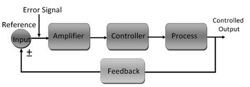
Closed-Loop Control System
The main advantages of the closed-loop control system are accurate, expensive, reliable, and requires high maintenance