Unit – 5
Introduction to Mechatronics
Q1) Explain the advantages and disadvantages of mechatronics
A1) Advantages of Mechatronics
• It is cost effective and it can produce high quality products.
• It serves effectively for high dimensional accuracy requirements.
• It provides high degree of flexibility to modify or redesign the systems.
• It provides excellent performance characteristics.
• It Results in automation in production, assembly and quality control.
• Mechatronic systems provide the increased productivity in manufacturing organization.
• It has greater extend of machine utilization.
• Higher life is expected by proper maintenance and timely diagnosis of the fault.
Disadvantages of Mechatronics
• The initial cost is high.
• Maintenance and repair may workout costly.
• Multi-disciplinary engineering background is required to design and implementation.
• It needs highly trained workers to operate.
Q2) What are the Industrial applications of Mechatronics
A2) Mechatronics is widely used in your day-to-day life.
It is used in appliances like washing machines and dishwashers.
It's also used in measuring devices like testing of sensors, and calibration devices.
Moreover, its uses in automatic air conditioning systems, automatic door systems, and security systems improve the quality of life as well as the security of secure facilities.
Furthermore, it's used in unmanned aerial vehicles as well as automatic guided vehicles for mine detection. Mechatronics technology use cuts across industries and is useful to just about everyone.
Q3) Explain the – Kinematic Chains
A3) Kinematic chain: It is a linkage of elements and joints that transmit a controlled output motion related to a given input motion.
Kinematic Pair is the combination of the links or the machine elements. Likewise, the Kinematic Chain is also the combination of the Kinematic pairs.
The most important kinematic chains are those with four lower pairs. A lower pair is called when the pair is sliding or turning or screw pair.
Q4) What are the types of kinematic chain explain it briefly
A4) Four Bar Chain Or Four Bar Mechanism
Four Bar chain is also is known as the Quadric Cycle chain. The four Bar chain will have four links, each of these links will form one turning pair. These four links can be of different lengths.
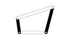
Four Bar Mechanism
According to Grashof’s law for a Four bar mechanism, the sum of the shortest and the longest link lengths should be greater than the sum of the other two links.
One of the most important considerations for any mechanism is that one of the links should complete one complete revolution. Which will be the input crank for the mechanism.
In this Four bar mechanism as shown in the above gif image, It converts the rotary motion into the oscillating motion.
Single Slider Crank Chain
The Single Slider Crank Chain mechanism is nothing but the modified Four Bar mechanism. Unlike all the four turning pairs in the four-bar mechanism, The Single slider crank chain mechanism will consist of the three turning pairs and one sliding pair.
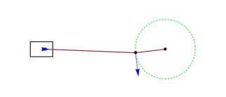
Single Slider Crank Chain Mechanism
As you can see the 1. crank, 2. connecting link 3. fixed base as the fixed link 4. position moving in the crosshead are the four links. and the piston and the crosshead are making the sliding pair and the rest are making the turning pairs.
All the reciprocating Engines will be running on this mechanism only. This mechanism will convert the reciprocating motion into the rotary motion as well as the vice versa.
Double Slider Crank Chain
The name itself represent that it will have two sliding pairs and two turning pairs in the double slider crank chain mechanism.
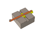
Double Slider Crank Chain
As you can see the above picture which is an example for the Double slider crank chain mechanism. In that, we have four elements (two sliding elements, one lever, slotted one base).
The two sliding elements joined by the lever element. This liver will be making two turning pairs with the two sliding elements. The slotted base which will make the two sliding pairs with the sliding elements.
Q5) What is Cam?
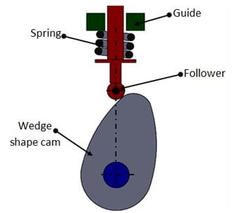
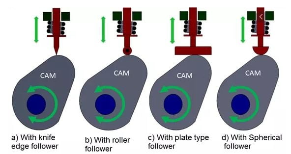
A5) When the two links are connected either along a line or at a point, it is called a higher pair. Two such higher pair mechanisms will be included in a cam-follower system. A higher pair mechanism is known as cam and follower.
For the smooth functioning of a cam-follower mechanism, it is imperative that the follower should move smoothly without requiring too much input power, which means the follower should not jam, during its movement.
In an IC engine the valves have to be kept open; first, then close it and keep it closed, all these timing operations can be easily set by having cam-follower mechanisms. In the case of linkages, we study about planar linkages or two- dimensional linkages and more.
Q6) Explain cam different types
A6) The following five types of CAM:
Disc or Plate Cam
Cylindrical Cam
Translating Cam
Radial Cam
Wedge Cam
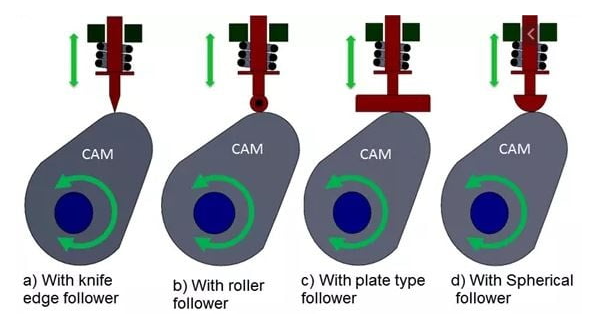
Disc or Plate Cam:
A disc or plate cam is a type of cams in which follower moves radially from the center of rotation of the cam. These cams are very popular due to their simple design and compactness that can be fitted into remote places. The application of Disc or Plate Cam is in I.C engines and machine tools.
Cylindrical Cam:
A Cylindrical cam is the cam in which the cylinder rotates about its axis has a circumferential contour cut on the cylinder surface. They are also of two types in the first types a groove is cut on the surface of the cam and the roller and has a positive oscillating motion. Another one is having a cylinder as the working surface. In this type of cam spring-loaded follower translates along the parallel axis to the rotating cylinder.
Translating Cam:
Translating cam is the type of cam in which cam can move in a horizontal plane. The follower attached too, it has the motion constrained with the help of the spring. Sometimes groove cams are used in which the follower motion is achieved without the use of the spring.
Radial Cam:
If the input link also called cam rotates as angular motion, then cam has rotational or angular motion and then we call it a radial cam.
This profiled body is called the cam. This has a revolute pair with the fixed link that is the foundation or fixed link. Cam is the revoluting link. There is a revolute pair between fixed link and the cam and the output link is the follower. If this cam rotates depending on the profile or shape of the cam, the follower will have translatory motion along with this prismatic pair between fixed link and the follower.
Wedge Cam:
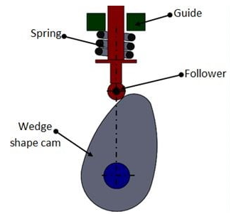
If the cam has a linear motion, then we call it a wedge cam. Wedge cam has a four-link mechanism, first is the fixed link, the cam which looks like a wedge is the other link. It depends on the profile of this wedge, as this cam oscillates in the horizontal direction, the follower will oscillate along the vertical direction along with this prismatic pair or this guide.
Q7) Describe the Train Ratchet Mechanism
A7) A toothed mechanism for the conversion of reciprocating rotary motion into intermittent rotary motion in one direction.
As shown in Figure 1, a ratchet mechanism consists of a ratchet wheel (1), a driving pawl (2), an arm (3), a locking pawl (4), and a support (0). The driving pawl engages the teeth of the ratchet wheel under the action of a spring or of its own weight. When the arm moves counterclockwise, the driving pawl turns the ratchet wheel through a certain angle. When the arm moves clockwise, the catch slips past one or more teeth, but the locking pawl prevents the clockwise rotation of the ratchet wheel.
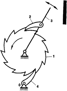
Figure. Diagram of a ratchet mechanism
Ratchet mechanisms are used in, for example, bicycles and machine tools. In loadlifting machines, ratchet mechanisms prevent the drum of the winch from moving backward under the weight of the load.
Q8) Explain the Belt Drive
A8) Power transmission by belt drive is one of the most common and universally used methods of transmission system when two shafts are parallel (up to 10 m) to each other as shown in Fig. A belt drive consists of two parallel shafts and a pulley is mounted on each shaft.
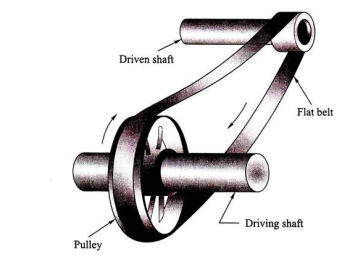
An endless belt runs over the surface of the pulley. There may be slippage between them and hence it cannot be called as a positive drive. When the belt runs over the pulley, there is always a friction which acts in between the pulley surface and the belt surface in the opposite direction of motion. The belt transmits power by friction only. The belt drive system can be used for long center-to-center distance of the shaft. For effective transmission, friction between the pulley surface and the belt surface should be as high as possible.
As it is well known, in most of the systems friction is not a desirable phenomenon and should be as minimum as possible.
1. Flat Belt Drive:
A belt is a thin band made of leather, synthetic rubber, canvas, or thread embedded in rubber or balata. These belts are made flat and rectangular in cross section. The belts are made endless by joining the two ends of the belt by pins or stitching as shown in Fig.
The system may be applicable for individual drive or group drive. Individual belt drive can be used when each machine will have its own electric motor. In case of group drive, a high-capacity motor drives an overhead shaft called main shaft or live shaft and the main shaft drives another shaft called counter shaft which drives another machine shaft.
The rotational power from driving pulley to the driven pulley is transmitted due to friction between the belt surface and the pulley surface. The belt will have two sides, one side will be in tension called tension side where as the other side will be in lesser tension called slack side as shown in Fig. 9.3.
The tension side (T1) and the slack side (T2) of the belt depend on the direction of rotation of the driving pulley.
Q9) Define the advantage and disadvantage of belt drive
A9) Advantages:
i. Simple method, universally used arrangement, operation is smooth if the belt is of proper size.
ii. Low maintenance cost and long life.
iii. Flexibility is more.
iv. The level of shock is less.
v. Suitable for two parallel shafts.
vi. Suitable for long distances between two center-to-center shafts.
Disadvantages:
Endless belt is made by joining the two ends by pins. The belt tends to get damaged near the joints which reduces its life. This may require periodic replacement of the belt.
ii. The system is not suitable for short-distance shaft.
iii. Efficiency is found less due to slippage and creep, if the size of the belt is not proper.
iv. The system is not a positive drive.
Q10) What are the Pressure Control Valves
A10) Pressure-control valves are found in practically every pneumatic and hydraulic system. They help in a variety of functions, from keeping system pressures below a desired limit to maintaining a set pressure level in part of a circuit. Different types of pressure control valves include relief, reducing, sequence, counterbalance, safety, and unloading. All of them are typically closed valves, except for reducing valves, which are usually open. For most of these valves, a restriction is necessary to produce the required pressure control. One exception is the externally piloted unloading valve, which depends on an external signal for its actuation, which normally comes from a digital pressure regulator. In certain applications, like ventilators and anesthesia machines, the flow must be consistent at all times. Variations in the flow of gases can lead to serious injury or death. That’s why control valves are so important.
Why do we need to use a pressure control valve