{ Where, [
|
 , BC=800
 ,CA= 800
 take E
|
|
Step-1 degrees of freedom Discretization –
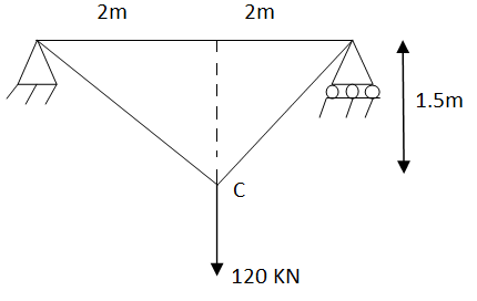
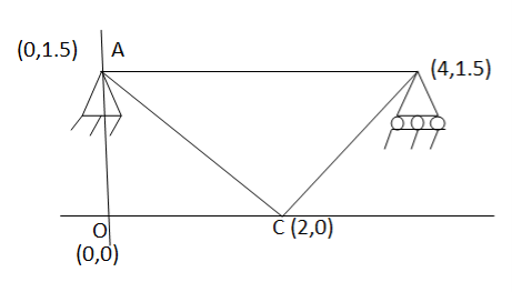
Assume x-axis horizontal through point (& vertical through point A). the co-ordinates of node A(0,1.5) , B(4,1.5) & C(2,0) . take E in Gpa.
Step-2 element stiffness matrices Stiffness matrix of element AB .
Stiffness matrix of element BC
Stiffness matrix of element CA
Step 3- global stiffness matrix Total Dof are 06, size of stiffness matrix 6*6
Step -4 reduced stiffness matrix Since
Step -5 equation of equilibrium
|
 young modulus is 200 KN/
 . Determine deflection at loaded joint.
|
Step 1 – degree of freedom ;- Discretization
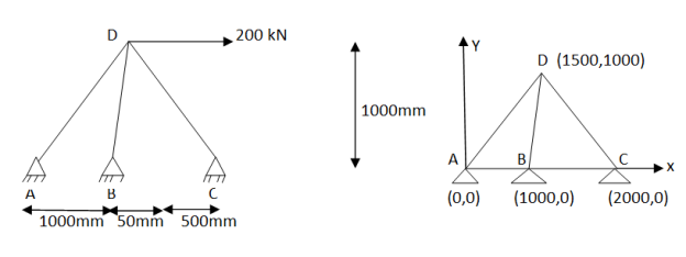
Assume origin support A(0,0). The co-ordinates of other nodes& B(1000,0), C(2000,0) and D(1500,1000)
Step -2 element stiffness matrices Stiffness matrix of element AD
Step – 4 equations of equilibrium
|
 young modulus is 200 Gpa.
|
Step -1 degree of freedom (06) Discretization
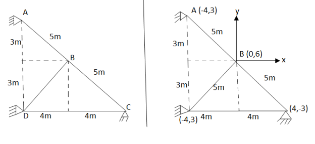
Assume origin point B. the co-ordinates points are
Step -2 stiffness matrix of element AB .
Stiffness matrix at element DB.
Step 3- reduced stiffness matrix
Step 4- equation of equilibrium
|
|
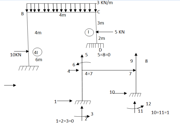
Step -1 total DoF =12 (three DOf at each node, two displacement & one rotation) No. of elements 03 (AB,BC,CD) Discretization
Step 2- element stiffness matrix Element stiffness matrix from AB (column member)
Imposing boundary conditions 5=8=0 Element stiffness matrix for DC
Imposing boundary conditions 10=12=0 Step -3 reduced stiffness matrix Since horizontal sway at B& C are same (4=7) we can modify the above stiffness matrix as
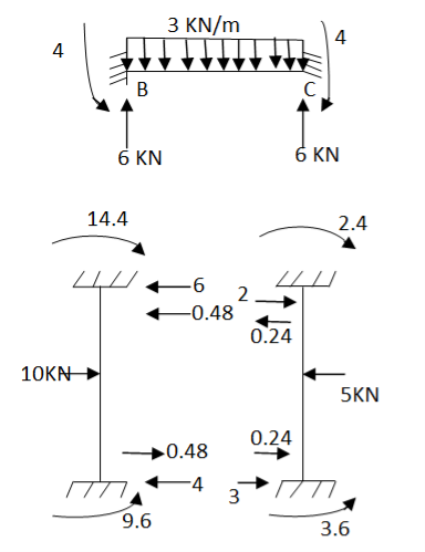
Step -4 element nodal load vector
Fig.6
Reduced element nodal load vector
Step -5 equivalent load vector {f}= {q}+ joint forces
Step -6 equation of equilibrium
Step -7 moment calculations
Member AB
Member BC
Member DC
|
|
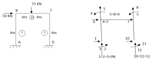
Step -1 total DOf =12 (three dof at each node , two displacements & one rotation)
Step -2 element stiffness matrix for column AB
Element stiffness matrix of beam Bc
Element stiffnes matrix of beam DC.
Imposing boundary condition 1=2=3=5=8=10=11=12=0 Step -3 reduced stiffness matrix Since horizontal sway at B &C are same (4=7) , we can modify the above stiffness matrix as
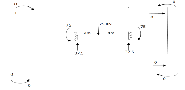
Step -4 element nodal load vector
Fig.8
Reduced element nodal load vector
Step -5 equivalent load vector
Step -6 equation of equilibrium
Step -7 moment calculations
Member AB
Member BC
Member DC
|

|
 S9)
S9)
We know that
&
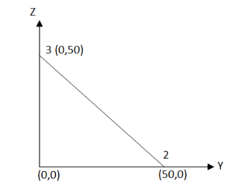
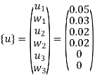
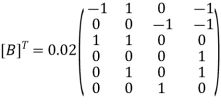
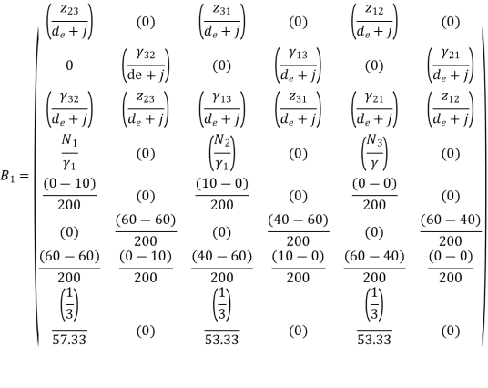
Substitute all this values in {B}
Put =E =
We know that stiffness matrix
Note ; matrix form [k]= (6*6)
To find stresses
Note – matrix form = 4*1
|
|
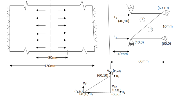
Stiffness matrix for element 1
For the both elements
The stiffness matrices for element
|


