Unit - 4
Review of particle dynamics
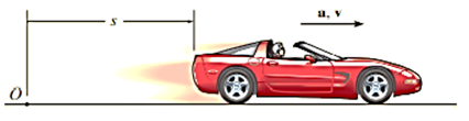
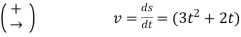
Q1) The car in figure moves in a straight line such that for a short time its velocity is defined by  ft/s where t is in seconds. Determine its position and acceleration when
  and if
  ,
,  .
.
A1)
Coordinate system
The position coordinate extends from the fixed origin O to the car, positive to the right.
Position.
Since  This equation relates
  Nothing that
  when
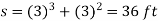
when  we have*
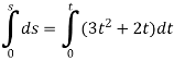


When 
Acceleration.
Since  the acceleration is determined from
  .
.
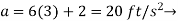
Since this equation relates 
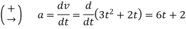
When t=3s,
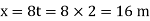
Q2) At any instant the horizontal position of the weather balloon is defined by  where t is in seconds and x is in meters. If the equation of the path of the balloon is
  . Determine the magnitude and direction of the velocity and the acceleration when t = 2 s.
A2) Velocity:
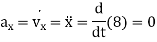
The velocity component in the x direction is
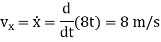
At t = 2 s
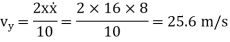
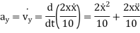
The velocity component in the y direction is

At t = 2 s
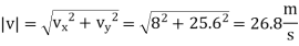
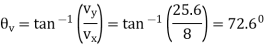
The direction is tangent to the path
Acceleration:
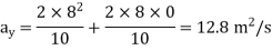
Magnitude of acceleration is

Direction of acceleration is

Q3) For a short time, the path of the plane is described by  If the plane is rising with a constant velocity of 10 m/s, determine the magnitudes of the velocity and acceleration of the plane when it is at y = 100 m.
A3) When  or
or  Also, since
  , then


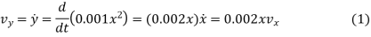
Velocity
Relationship between the velocity components, we have
Thus
The magnitude of the velocity is therefore

Acceleration: Using the chain rule, the time derivative of Eq. (1) gives the relation between the acceleration components.

When 


The magnitude of the plane’s acceleration is therefore

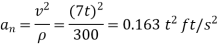
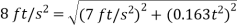
Q4) A race car C travels around the horizontal circular track that has a radius of 300 ft. If the car increases its speed at a constant rate of 7 ft/s2 starting from rest, determine the time needed for it to reach an acceleration of 8 ft/s2. What is its speed at this instant?
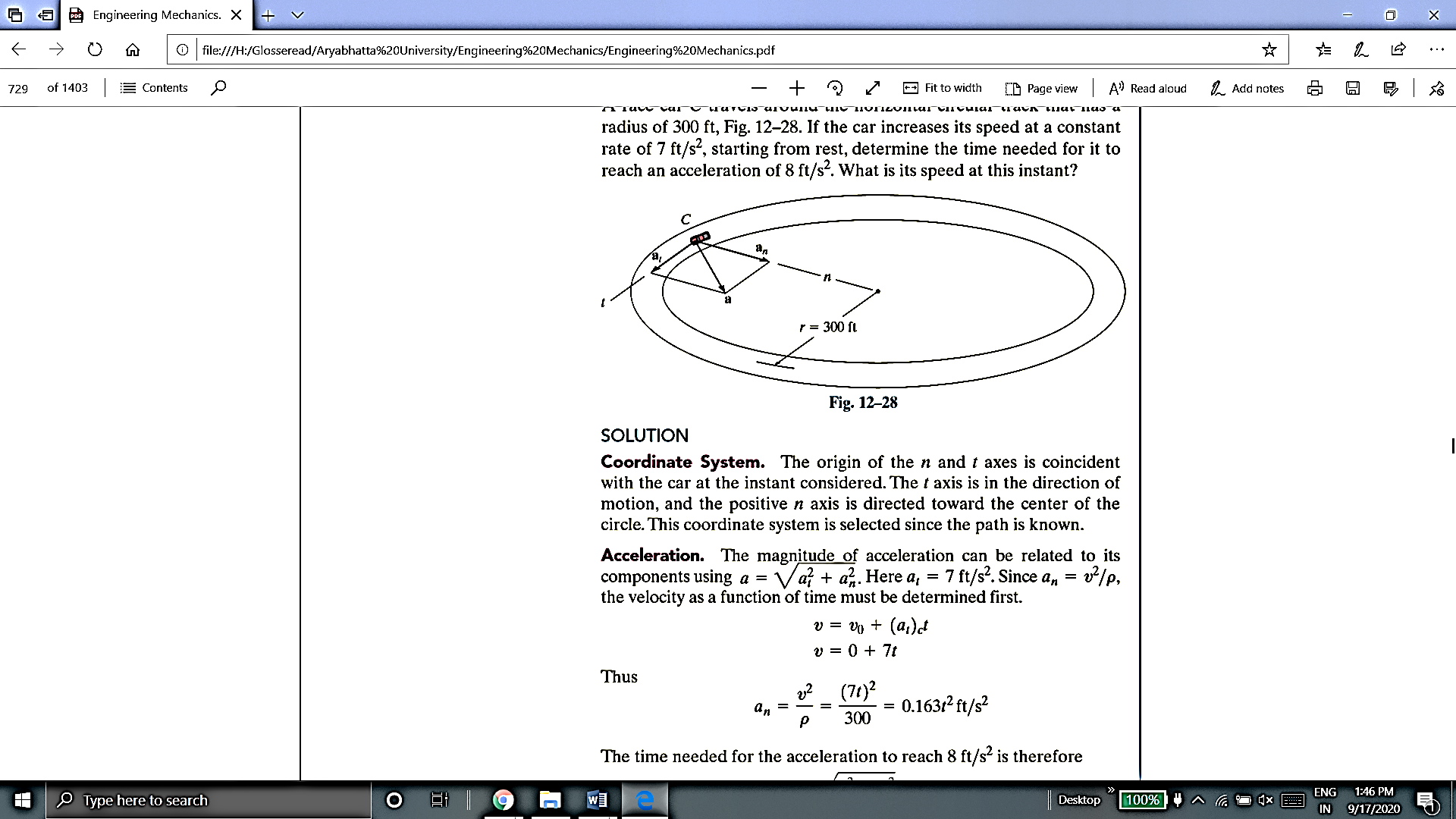
A4) Coordinate System
The origin of the n and t axes is coincident with the car at the instant considered. The t axis is in the direction of motion, and the positive n axis is directed toward the center of the circle. This coordinate system is selected since the path is known.
Acceleration
The magnitude of acceleration can be related to its components using  . Here
  . Since
  . The velocity as a function of time must be determined first.

Thus
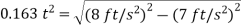
The time needed for the acceleration to reach  is therefore

Solving for the positive value of t yields

Velocity. The speed at time  is
is
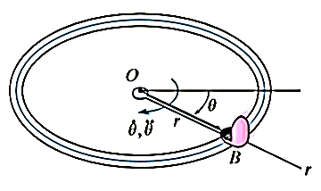
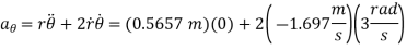
Q5) The amusement park ride shown in Fig below consists of a chair that is rotating in a horizontal circular path of radius r such that the arm OB has an angular velocity  and angular acceleration
  . Determine the radial and transverse components of velocity and acceleration of the passenger. Neglect his size in the calculation.
A5)
Coordinate system
Since the angular motion of the arm is reported, polar coordinates are chosen for the solution. Here θ is not related to r, since the radius is constant for all θ.
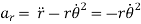
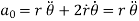
Velocity and Acceleration:
It is first necessary to specify the first and second time derivatives of r and θ. Since r is constant, we have

Thus


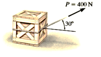
Q6) The 50-kg crate shown in Fig below rests on a horizontal surface for which the coefficient of kinetic friction  is If the crate is subjected to a 400-N towing force as shown, determine the velocity of the crate in 3 s starting from rest.
A6)
Using the equation of motion, we can relate the crate’s acceleration to the force causing the motion. The crate’s velocity can then be determined using kinematics.
Free-Body Diagram:
The weight of the crate is
 As shown in Fig. the frictional force has a magnitude
  and acts to the left, since it opposes the motion of the crate. The acceleration a is assumed to act horizontally, in the positive x direction. There are two unknowns, namely
  and a.
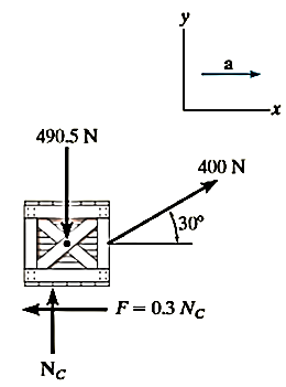
Equations of motion
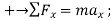
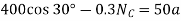 (1)
(1)
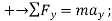
 (2)
(2)
Solving Eq.2 for  , substituting the result into Eq.1 and solving for a yields

Kinematics
Notice that the acceleration is constant, since the applied force P is constant. Since the initial velocity is zero, the velocity of the crate in 3 s is
(+ )
) 
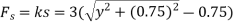
Q7) A smooth 2-kg collar C, shown in Fig, is attached to a spring having a stiffness k = 3 N/m and an unstretched length of 0.75 m. If the collar is released from rest at A, determine its acceleration and the normal force of the rod on the collar at the instant y = 1 m
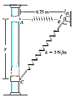
A7) Free-Body Diagram:
The free-body diagram of the collar when it is located at the arbitrary position y is shown in Fig. Furthermore, the collar is assumed to be accelerating so that “a” act downward in the positive y direction. There are four unknowns, namely  and θ.
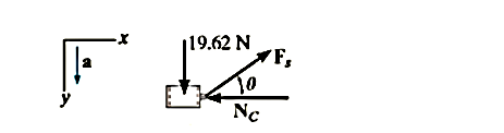
Equation of Motion:

 (1)
(1)
+
 (2)
(2)
From Eq. 2 it is seen that the acceleration depends on the magnitude and direction of the spring force. Solution for  and a is possible once
  and θ are known.
The magnitude of the spring force is a function of the stretch s of the spring; i.e.,  . Here the unstretched length is
  Fig. 13-19a; therefore,
 . Since
  , then
 (3)
(3)
From Fig 13-99a, the angle θ is related to y by trigonometry.
 (4)
(4)
Substituting  into Eqs. 3 and 4 yields
  and
and  . Substituting these results into Eqs. 1 and 2, we obtain

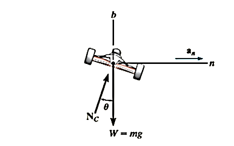
Q8) Determine the banking angle for the race track so that the wheels of the racing cars will not have to depend upon friction to prevent any car from sliding up or down the track. Assume the cars have negligible size, a mass m, and travel around the curve of radius  with a constant speed v.
A8) Free-Body Diagram:
As shown in Fig. and as stated in the problem, no frictional fore acts on the car. Here  represents the resultant of the ground on all four wheels. Since
  can be calculate, the unknowns are
  and θ.
Equations of Motion;
Using the n, b axes shown,

 (1)
(1)
+
 (2)
(2)
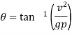
Eliminating  and m from these equations by dividing Eq.1 by Eq.2 we obtain

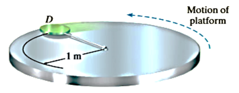
Q9) The 3-kg disk D is attached to the end of a cord as shown in Fig. The other end of the cord is attached to a ball-and-socket joint located at the center of a platform. If the platform rotates rapidly, and the disk is placed on it and released from rest as shown, determine the time it takes for the disk to reach a speed great enough to break the cord. The maximum tension the cord can sustain is 100 N, and the coefficient of kinetic friction between the disk and the platform is 
A9)
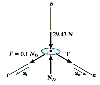
Free-Body Diagram:
The frictional force has a magnitude  and a sense of direction that opposes the relative motion of the disk with respect to the platform. It is this force that gives the disk a tangential component of acceleration causing v to increase, thereby causing T to increase until it reaches 100n. the weight of the disk is
  . Since
  can be related to v, the unknowns are
 and v.
Equations of Motion:

 (1)
(1)

 (2)
(2)

 (3)
(3)
Setting  , Eq. 1 can be solved for the critical speed
  of the disk needed to break the core. Solving all the equations, we obtain


Kinematics:
Since  is constant, the time needed to break the cord is


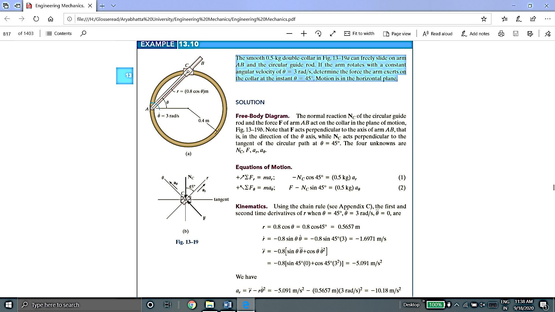
Q10) The smooth 0.5-kg double-collar can freely slide on arm AB and the circular guide rod. If the arm rotates with a constant angular velocity of  , determine the force the arm exerts on the collar at the instant
  450. Motion is in the horizontal plane.
A10) Free-body diagram: The normal reaction  of the circular guide rod and the force F of arm AB act on the collar in the plane of motion. Note that F acts perpendicular to the axis of arm AB, that is, in the direction of the θ axis, while
  acts perpendicular to the tangent of the circular path at
  . The four unknowns are
  .
.
Equations of Motion:
 (1)
(1)
 (2)
(2)
Kinematics:
Using the chain rule (see Appendix C), the first and second time derivative of r when 
 are
are


 ]
]

We have
Substituting these results into Eqs. (1) and (2) and solving, we get


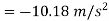
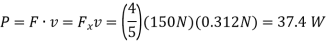
Q11) The man in Figure pushes on the 50-kg crate with a force of  Determine the power supplied by the man when
  . The coefficient of kinetic friction between the floor and the crate is
  . Initially the create is at rest.
A11)
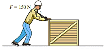
To determine the power developed by the man, the velocity of the 150-N force must be obtained first. The free-body diagram of the crate is shown in Fig. applying the equation of motion

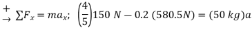
The velocity of the crate when  is therefore
The power supplied to the crate by the man
When t=4s is therefore
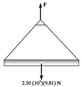
Q12) For a short time the crane lifts the 2.50-Mg beam with a force of Determine the speed of the beam when it has risen. Also, how much time does it take to attain this height starting from rest?
A12) We can solve part of this problem using the principle of work and energy since it involves force, velocity, and displacement. Kinematics must be used to determine the time. Note that at  , so motion will occur.
Work (Free-Body Diagram). As shown on the free-body diagram, the lifting F does positive work, which must be determined by integration since this force is a variable. Also, the weight is constant and will do negative work since the displacement is upwards.
Principle of work and Energy.
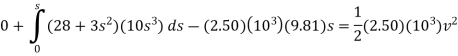


When 

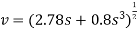
Kinematics. Since we were able to express the velocity as a function of displacement, the time can be determined using  = ds/dt. In this case,
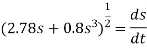
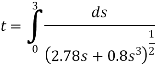
The integration can be performed numerically using a pocket calculator. The result is

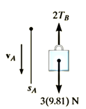
Q13) Blocks A and B shown in Figure below have a mass of 3 kg and 5 kg, respectively. If the system is released from rest, determine the velocity of block B in 6 s. Neglect the mass of the pulleys and cord.
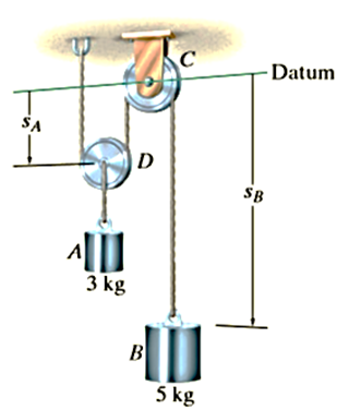
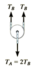
A13) Free-Body Diagram. Since the weight of each block is constant, the cord tensions will also be constant. Furthermore, since the mass of pulley D is neglected, the cord tension  . Note that the blocks are both assumed to be moving downward in the positive coordinate directions,
  and
and  .
.
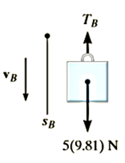
Principle of Impulse and Momentum.
Block A:
(+ )
) 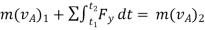


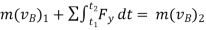
Block B:
(+ )
) 


Kinematics. Since the blocks are subjected to dependent motion, the velocity of A can be related to that of B by using the kinematic analysis a horizontal datum is established through the fixed point at C, Fig. 15-6a, and the position coordinates,  and
and  , are related to the constant total length
  of the vertical segments of the cord by the equation

Taking the time derivative yields
 (3)
(3)
As indicated by the negative sign, when B moves downward A moves upward. Substituting this result into Eq. 1 and solving Eq. 1 and 2 yields

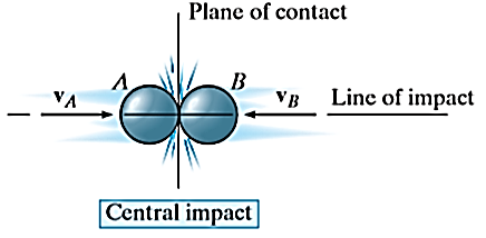
Q14) Define Impact and state its types.
A14) Impact occurs when two bodies collide with each other in a very short period of time, resulting relatively huge (impulsive) forces to be exerted between the bodies.
Example: striking of a hammer on a nail, a golf club on a ball
There are two types on impact:
Central impact occurs when the direction of motion of the mass centers of the two colliding particles is along a line passing through the mass centers of the particles. This line is called the line of impact which is perpendicular to plane of contact.
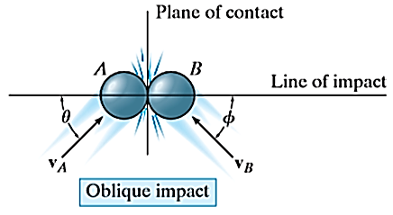
2. Oblique impact
When the motion of one or both of the particles make an angle with the line of impact, then the impact is said to be oblique impact.