Unit - 5
Introduction to Kinetics of Rigid Bodies
Q1) Explain different types of motion of a rigid body
A1) There are three types of motion of a rigid body
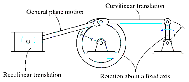
Translation motion
Translation motion occurs when a line (generally axis) in the body remains parallel to its initial orientation throughout the motion.

If the path of motion of any two lines on the rigid body are parallel or are in a straight line, then the translation is termed as rectilinear translation.
If the path of motion of any two lines on the rigid body are along the fixed curve, then the translation is termed as curvilinear translation.
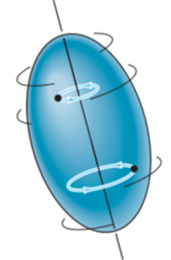
Rotation Motion:
When a rigid body is subjected to the rotation about a fixed axis, as shown in fig below, all the particles of the body, except those which lie on the axis of rotation, move along circular paths whose center lies on the axis of rotation.
General Plane motion:
General plane motion of a rigid body refers to a combination of translation and rotation motion.
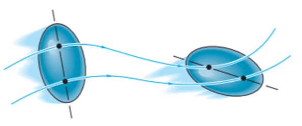
General planar motion refers to the simultaneous rotational and translational motion of a planar body in a 2-D plane.
General planar motion can be fully specified by knowing both the angular rotation of a line fixed in the body and the motion of any point on the body.
Q2) Explain the concept of instantaneous center of rotation.
A2) Consider a plane body P having a non-linear motion relative to another plane body q as shown in figure below.
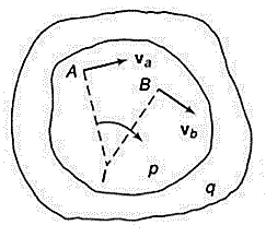
Let the velocities of two points A and B on the plane body P be  and
and  respectively in the direction as shown in figure above.
The body if in non-linear motion, then at any instant the body can be imagined to be rotating about some point. This point lies on the line perpendicular to the direction of vibration. If we draw perpendicular lines to the direction of velocities at point A and B respectively, then the point of intersection is the point at which the body p is imagined to be rotating. Let this point be 1. Then point 1 is called as instantaneous center of rotation (ICR) for the body p in non-linear motion.
This property of instantaneous center of rotation is true only for an instant and at the next instant, the new point will become the instantaneous point of rotation. This is the reason that this point is not called as center of rotation but instantaneous center of rotation.
ICR is not located at the center of curvature of the path apparently taken by a point of one body relative to other body. In spite of this limitation, ICR is a useful tool for understanding the kinematics of a planar body in non-linear motion or in general plane motion.
If the intersection of the perpendicular lines lies outside planar body, then ICR will also lie outside of the body. If the direction of velocities are parallel to each other, then the perpendicular lines will also be parallel to each other and hence, these lines do not intersect. In such cases, ICR lies at infinity.
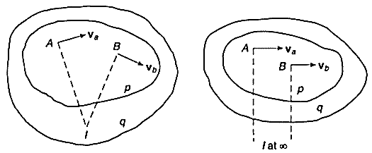
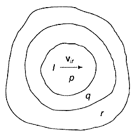
The velocity of the body at any point is proportional to the distance of the point from the ICR. Hence, the velocity of point 1 (ICR) itself is zero, as the distance is zero. This implies that, at ICR, the two bodies p and q are relatively at rest. Means, there is no relative motion at ICR between the two bodies.
Now, consider the body q is in relative motion to the third body r. The relative motion of ICR with respect to third body r would be same irrespective of the point is considered on body p or q.
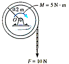
Q3) The 30–kg disk, shown in Figure, is pin supported at its center. Determine the number of revolutions it must make to attain an angular velocity of  starting from rest. It is acted upon by a constant force
  which is applied to a cord wrapped around its periphery, and a constant couple moment
  . Neglect the mass of the cord in the calculation.
A3) Kinetic energy:- since the desk rotates about a fixed axis , and it is initially at rest then


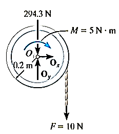
Work(free-body design). As shown in fig. the pin reaction  and the weight (294.3N) do no work , since they are not displaced . the couple moment, having a constant magnitude, does positive work
  as the disk rotates through a clockwise angle of
  rad, and the constant force F does positive work
  =
= as the cord moves downwards =
Principle of work and energy


Q4) The 700-kg pipe is equally suspended from the two tines of the fork lift shown in the photo. It is undergoing a swinging motion such that when  it is momentarily at rest. Determine the normal and frictional forces acting on each tine which are needed to support the pipe at the instant
  . Measurements of the pipe and the suspender are shown in Fig. Neglect the mass of the suspender and the thickness of the pipe.
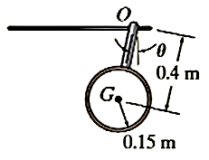
A4) We must use the equations of motion to find the forces on the times since these forces do no work. Before doing this, however , we will apply the principle of work and energy to determine the angular velocity of the pipe when
kinetic energy(kinetic diagram).
Since the pipe is originally at rest, then

The final kinetic energy may be computed with reference to either the fixed-point O or the center of mass G. for the calculation we will consider the pipe to be a thin ring so that  . If point G is considered, we have


If point O is considered then the parallel -axis theorem must be used to determine  .hence


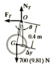
Work(free- body diagram)
The normal and frictional forces on the tines do no work since they do not move as the pipe swings. The weight does positive work since the weight moves downward through a vertical distance 
Principle of work and energy


Equations of motion: - referring to the free body and kinetic diagram shown in fig. and using the result for  , we have


Since 


These are two tines used to support the load, therefore


Q5) The car shown in Figure has a mass of 2 Mg and a center of mass at G. Determine the acceleration if the rear “driving” wheels are always slipping, whereas the front wheels are free to rotate. Neglect the mass of the wheels. The coefficient of kinetic friction between the wheels and the road is 
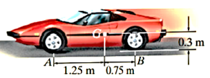
A5)
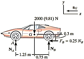
Free body diagram:- As shown in fig. the rear-wheel frictional forces  pushes the car forward and since slipping occurs ,
 the frictional forces acting on the front wheels are zero , since these wheels have negligiable mass. There are three unknowns in the problem
  . Here we will sum moments about the mass center. The car ( point G) accelerates to the left, i.e in the negative x direction
Equations and motion.
 -----1
 -----2

Solving
αG=1.59m/s2
NA=6.88KN
NB=12.7KN
Q6) A uniform 50-kg crate rests on a horizontal surface for which the coefficient of kinetic friction is Determine the acceleration if a force of is applied to the crate as shown in Figure.
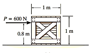
A6)
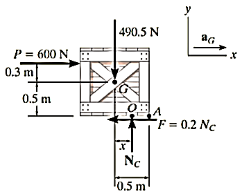
Free – body diagram :- The force P can cause the crate either to slide or to tip over. As shown in fig it is assumed that the crate slides, so that  also the resultant normal force
 acts as O , a distance x ( where
  from the crates center line . the three unknown are
Equations of motion


Solving
NC=490.5N
x=0.467m
αG=10.0m/s2
since x=0.467 m < 0.5m, indeed the crate slides as originally assumed.
Q7) Explain D’Alembert’s principle for plane motion.
A7) D’Alembert’s principle states that, “if at any given moment to the active forces and the reactions of the constraints acting on a particle or rigid body is added the inertia force, the resultant force system will be in equilibrium and all the equations of statics will apply to it.”
D'Alembert’s principle provides a method of solving problems of dynamics by developing equations of motion in the form of equations of equilibrium.
In simple words, D’Alembert’s principle is just the principle of virtual work with the inertial forces added to the list of forces that do work.
Consider a body in general plane motion as shown in figure below.
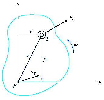
Consider this body is at rest and let  be the resultant external forces acting on a rigid body and
  be the virtual displacement of the body is s direction.
Then according to principle of virtual work,

This method is used for solving statics problems. In statics problems there are no accelerations.
We can extend this principle of virtual work for solving dynamics problems.
For the system of mass m and resultant acting forces  , according to Newton’s second law of motion,

We can make this dynamics problem look like a statics problem by defining an inertial force given by,

Now, for dynamics problems, principle of virtual work becomes,

As the virtual displacement is same for both the active forces and inertia forces,

This is D’Alembert’s principle used for solving the dynamics problems by using the concept of equilibrium conditions.
The above equation can be written as


Considering the rigid body in general plane motion as shown in figure below:
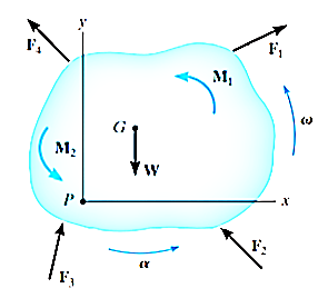
Applying D’Alembert’s principle, three independent scalar equations can be written to describe the general plane motion of a symmetrical rigid body.


Q8) At the instant shown in Figure, the 20-kg slender rod has an angular velocity of  . Determine the angular acceleration and the horizontal and vertical components of reaction of the pin on the rod at this instant.
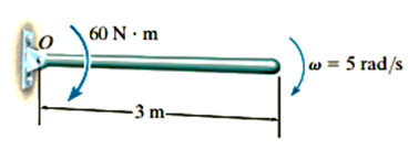
A8) Free- body and kinetic diagram: - as shown on the kinetic diagram, point G moves around a circular path and so it has two components of acceleration. It is important that the tangential component  act downwards since it must be in accordance with the rotational sense of
  . The three unknowns are
Equation of motion


Solving

A more direct solution to this problem would be to sum moments about point O to eliminate  and
and  and obtain a direct solution at
  . Here,


Also, since  for a slender rod, we can apply


Q9) The drum shown in Figure has a mass of 60 kg and a radius of gyration  . A cord of negligible mass is wrapped around the periphery of the drum and attached to a block having a mass of 20 kg. If the block is released, determine the drum’s angular acceleration.
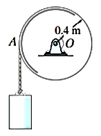
A9)
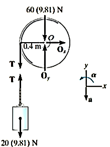
Free-body diagram :-
Here we will consider the drum and block separately. assuming the block accelerates downward at a, it creates a counterclockwise angular acceleration  of the drum. The moment of inertia of the drum is

There are five unknowns, namely 
Equations of motion: -applying the translational equations of motion  to the drum is of no consequences to the solution, since these equations involve the unknowns
  . Thus, for the drum and block, respectively


Kinematics: - since, the point of contact A between the cord and drum has a tangential component of acceleration a,

Solving the above equations


Q10) The slender rod shown in Figure has a mass m and length l and is released from rest when  . Determine the horizontal and vertical components of force which the pin at A exerts on the rod at the instant
  .
.
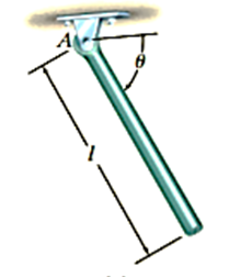
A10)
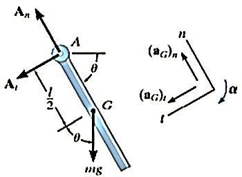
Free -body diagram :- the free body diagram for the rod in the general position  is shown in fig. for convenience , the force components at A are shown acting in the n and t directions . note that
  acts clockwise and so
  acts in the +t direction
The moment of inertia of the rod about point A is 
Equations of motion: -moment will be summed about A in order to eliminate 


Kinematics: - for a given angle  there are four unknowns in the above three equations;
 as shown by eq. 3,
  is not constant; rather, it depends on the position
  of the rod. The necessary fourth equation is obtained using kinematics, where
  can be related to
  by the equations

note that the positive clockwise direction for this equation agrees with that of eq, 3. this is important since we are seeking a simultaneous solution
in order to solve for  at
at  =90 eliminate
  from eq. 3 and 4 which yields

since 


Q11) Explain concept of virtual work and virtual displacement.
A11) In general, the definitions of the work of a force and a couple can be presented in terms of the actual movements which are expressed by differential displacements having values of  and
and  .
.
Consider now an imaginary or virtual movement of a body in static equilibrium, which indicates a displacement or rotation that is assumed and does not actually exist. This displacement is called as virtual displacement.
Virtual displacement is the displacement the force or couple would make on a body if the body was not in the static equilibrium or its motion would not be constrained.
These movements are first-order differential quantities and will be denoted by the symbols  and
and  (delta r and delta
  ), respectively.
The virtual work done by a force having a virtual displacement  is
is

Similarly, when a couple undergoes a virtual rotation  in the plane of the couple forces, the virtual work is

Consider a ball that rests on a floor. If there was no floor below the ball, then the ball would have been displaced due to its own weight. Then this imaginary displacement of the ball is nothing but the virtual displacement.
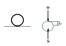
Q12) Explain principle of virtual work for a particle.
A12) According to the principle of virtual work if a body is in equilibrium, then virtual displacement of the body is zero for all the algebraic sum of the virtual work which is done by all the forces and moments of couple that are acting on the body. Thus,

For example, consider the free-body diagram of the particle (ball) that rests on the floor, Fig. below. If we “imagine” the ball to be displaced downwards a virtual amount  then the weight does positive virtual work
  , and the normal force does negative virtual work
  , For equilibrium the total virtual work must be zero, so that

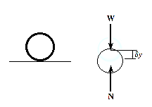
Since,  ,
,
Then,  , as required by
As seen from the above example, no added advantage is gained by solving particle and rigid-body equilibrium problems using the principle of virtual work. This is because for each application of the virtual-work equation, the virtual displacement, common to every term, factors out, leaving an equation that could have been obtained in a more direct manner by simply applying an equation of equilibrium.
Q13) Determine the angle for equilibrium of the two-member linkage shown in Figure. Each member has a mass of 10 kg.
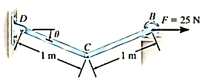
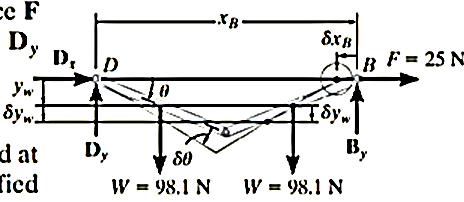
A13) Free-Body Diagram
The system has only one degree of freedom since the location of both links can be specified by the single coordinate (q=) θ. As shown on the free-body diagram in fig. when θ has a positive (clockwise) virtual rotation δθ, only the force F and the two 98.1 N weights do work. (The reactive forces  and
and  are fixed and
  does not displace along its line of action.)


Virtual Displacements
If the origin of coordinates is established at the fixed pin support D, then the position of F and W can be specified by the position coordinates  and
and  . In order to determine the work, note that, as required, these coordinates are parallel to the lines of action of their associated forces. Expressing these position coordinates in terms of θ and taking the derivatives yields


It is seen by the signs for these equations, and indicated in fig.11-6b, that an increase in θ (i.e., δθ) causes a decrease in  and an increase in
  .
.
Virtual-work equation
If the virtual displacements  and
and  were both positive, then the forces W and F would do positive work since the forces and their corresponding displacements would have the same sense. Hence, the virtual-work equation for the displacement δθ is
Substituting (1) and (2) into Eq.3 in order to relate the virtual displacements to the common virtual displacement δθ yields

Notice that the “negative work” done by F (force in the opposite sense to displacement) has actually been accounted for in the above equation by the “negative sign” of Eq.1. Factoring out the common displacement  and solving for θ, nothing that
  yields

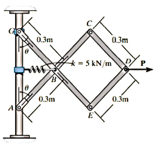
Q14) Determine the required force P in Figure, needed to maintain equilibrium of the scissors linkage when. The spring is unstretched when. Neglect the mass of the links.
A14) Free-Body Diagram
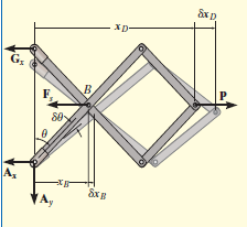
Only  and P do work when θ undergoes a positive virtual displacement δθ, Fig. For the arbitrary position θ, the spring is stretched
  , so that


Virtual Displacements.
The position coordinates,  and
and  measured form the fixed point A, are used to locate
  and P. These coordinates are parallel to the line of action of their corresponding forces. Expressing
  and
and  in terms of the angle θ using trigonometry,


Differentiating, we obtain the virtual displacements of points B and D.
 (1)
(1)
 (2)
(2)
Virtual-Work Equation:
Force P does positive work since it acts in the positive sense of its virtual displacement. The spring force  , does negative work since it acts opposite to its positive virtual displacement. Thus, the virtual-work equation becomes


Since  then this equation requires

When 

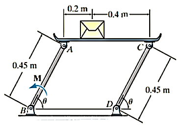
Q15) If the box in Figure has a mass of 10 kg, determine the couple moment M needed to maintain equilibrium when. Neglect the mass of the members.
A15)
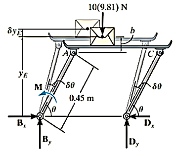
Virtual displacements:
The position coordinate  , measured from the fixed-point B, located the weight, 10(9.81) N. Here,

Where b is a constant distance. Differentiating this equation, we obtain
 (1)
(1)
Virtual-Work Equation
The virtual-work equation becomes


Substituting Eq.1 into this equation


Since  , then

Since it is required that  , then

Q16) Explain Stability of equilibrium.
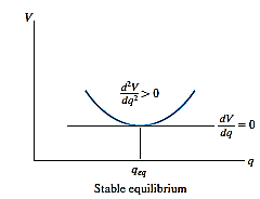
A16) The potential function V of a system can also be used to investigate the stability of the equilibrium configuration, which is classified as stable, neutral, or unstable.
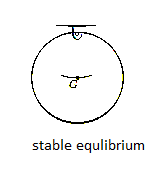
Stable Equilibrium: A system is said to be stable if a system has a tendency to return to its original position when a small displacement is given to the system. The potential energy of the system in this case is at its minimum. A simple example is shown in Fig. below. When the disk is given a small displacement, its center of gravity G will always move (rotate) back to its equilibrium position, which is at the lowest point of its path. This is where the potential energy of the disk is at its minimum.
The graph represents stable equilibrium for one degree of freedom system.
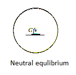
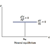
Neutral Equilibrium: A system is said to be in neutral equilibrium if the system still remains in equilibrium when the system is given a small displacement away from its original position. In this case, the potential energy of the system is constant. Neutral equilibrium is shown in Fig. below, where a disk is pinned at G. Each time the disk is rotated, a new equilibrium position is established and the potential energy remains unchanged.
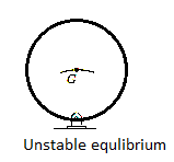
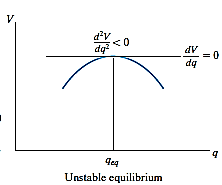
Unstable Equilibrium: A system is said to be unstable if it has a tendency to be displaced further away from its original equilibrium position when it is given a small displacement. The potential energy of the system in this case is a maximum. An unstable equilibrium position of the disk is shown in Fig. below. Here the disk will rotate away from its equilibrium position when its center of gravity is slightly displaced. At this highest point, its potential energy is at a maximum.
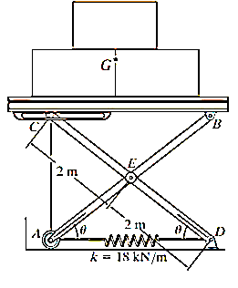
Q17) If the spring AD in Figure has a stiffness of 18 kN/m and is un-stretched when, determine the angle for equilibrium. The load has a mass of 1.5 Mg. Investigate the stability at the equilibrium position.
A17)
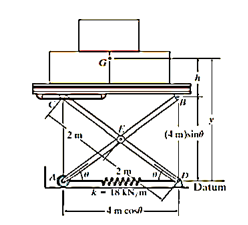
Potential energy
The gravitational potential energy for the load with respect to the fixed datum, shown in fig.

Where h is a constant distance. From the geometry of the system. The clongation of the spring when the load is on the platform is 
Thus, the elastic potential energy of the system is

The potential energy function for the system is therefore

Equilibrium
When the system is in equilibrium,


Since 

Solving by trial and error, 
Stability.
Taking the second derivative of eq.1

Substituting  yields

And for 

Q18) The uniform block having a mass m rests on the top surface of the half cylinder, Figure. Show that this is a condition of unstable equilibrium if h > 2R.
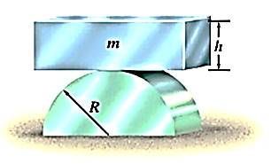
A18)
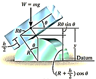
Potential function
The datum is established at the base of the cylinder, if the block is displaced by an amount θ from the equilibrium position, the potential function is

From Fig.11-18b,

Thus, 
Equilibrium position


Note htat  satisfies this equation.
Stability.
Taking the second derivatives of V yields

At 

Since all the constant are postive, the block is in unstabe equilibrium provided h>2R. because then 