Stress -
Stress =
1kPa = 1MPa = 106Pa = 106N/m2 = 1N/mm2 1GPa = 109Pa = 109N/m2 Strain –
|


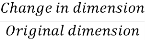
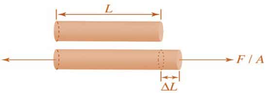
Normal Stress = Fig No 1.1 Normal Stress
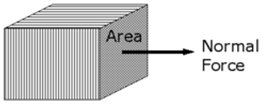
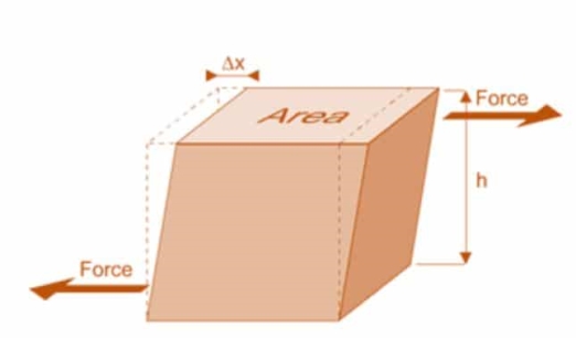
Fig No 1.2 Shear Stress
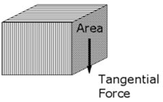
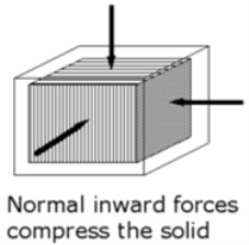
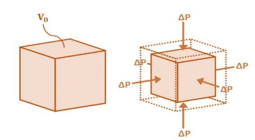
Fig No 1.3 Bulk Stress Bulk Stress = |


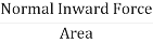

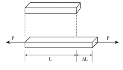
Normal Strain = Fig 1.4 Normal Strain |
Poisson’s Ratio (
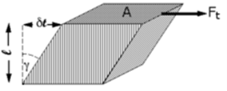
Fig No 1.5 Shear Strain Note 1: The angle is radians, not degrees. The volume of the solid is not changed by shear strain. Shear Strain =
Fig No. 1.6 Volumetric Strain Bulk Strain =
|


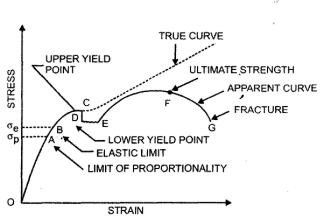
(A) For Brittle Metal –
Fig No 1.7 Stress-Strain Diagram (Brittle Metal) |
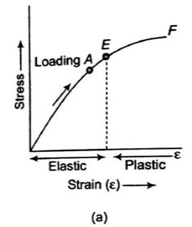
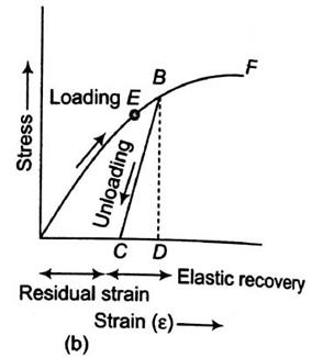
(B) For Ductile Metal –
Fig No 1.8 Stress-Strain Diagram (Ductile Metal) |
σT = K(εT)n |
 n is the strain hardening exponentn = 0 perfectly plastic solidn = 1 elastic solid for most metals, 0.1< n < 0.5 Q6) Explain the Different elastic constants in detail.A6)Different elastic constants are as follows:
 Young’s Modulus (E) =
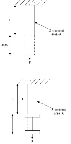
Fig 1.10: Body Subjected to Tensile Stress |

|
3. Rigidity ModulusWhen a body is subjected to shear stress the shape of the body gets changed, the ratio of shear stress to the corresponding shear strain is called rigidity modulus or modulus of rigidity. It is denoted by the letters “G” or “C” or “N”. Unit of rigidity modulus is mPa.
Fig 1.12: Shear Deformation of Body |

Relationship between Elastic Constants
E = 2G (1 +
E = 3K (1
E =
E = |


(A) Gradually Applied load –
Fig No 1.16 Gradually Applied Load |
(B) Suddenly Applied Load –
(C) Impact load:
Shear Stress – The shear stress is defined to be the ratio of the tangential force to the cross sectional area of the surface upon which it acts,
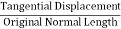
b) Shear Strain – The shear strain is defined to be the ratio of the horizontal displacement to the height of the block, α = δ x / h |


