Back to Study material
ISM

Unit - 2Shear Force and Bending Moment Diagrams Q1) Explain Shear Force Diagram (SFD) and Bending Moment Diagram (BMD).A1)
  • Shear and bending moment diagrams are analytical tools used in conjunction with structural analysis to help perform structural design by determining the value of shear force and bending moment at a given point of a structural element such as a beam.
  • These diagrams can be used to easily determine the type, size, and material of a member in a structure so that a given set of loads can be supported without structural failure.
  • Another application of shear and moment diagrams is that the deflection of a beam can be easily determined using either the moment area method or the conjugate beam method.
  • The algebraic sum of the vertical forces at any section of a beam to the right or left of the section is known as shear force.
  • It is briefly written as S.F. The algebraic sum of the moments of all the forces acting to the right or left of the section is known as bending moment.
  • It is written as B.M. In this chapter, the shear force and bending moment diagrams for different types of beams (i.e., cantilevers, simply supported, fixed, overhanging etc.) for different types of loads (i.e., point load, uniformly distributed loads, varying loads etc.) acing on the beams, will be considered.
  •  A)                Shear Force –            A shear force (SF) is defined as the algebraic sum of all the vertical forces, either to the left or to the right hand side of the section.

    https://lh4.googleusercontent.com/-Dth3nsr6rNux1jbaQMr9OLn6Xee6zhx1HcyGwgsN8G-fQsf3Ado_m3U-ruzmIMXZCymfFSqfUT1BK_q3_aAM7vtnw6KWaH0HSKlRHvhIhaXaJraS7p2hhOY48oEAtoSWlrPGg

     Fig 1. Shear ForceB)                Bending Moment –            A bending moment (BM) is defined as the algebraic sum of the moments of all the forces either to the left or to the right of a section.

    https://lh5.googleusercontent.com/-pXN-iPcVwXM-kSXfA_WRSv1JIMqT3r9X9DClSGUtmrAescIsH2ZhBQzUJOvL1Zsx2m6HF5zZd5iMIGaI13JkY-nMcofimiNCaeJqJGWhPuj8Y7b6y0f40v7YJmuJy0NCBj_iA

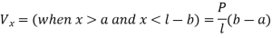
    Fig 2. Bending Moment

    Q2) Explain Sign Convention of SF and BM.A2)A)                For Shear force
  • To the right side of a section, external force acting in upward direction is treated as negative (remember this convention as RUN —» Right side of a section Upward force is Negative).
  • It is automatic that a downward force acting to the right side of a section be treated as positive.
  • The signs become just reversed when we consider left side of section. A shear force which tends to rotate the beam in clockwise direction is positive and vice versa.
  •  B)                For Bending Moment –
  • The internal resistive moment at the section that would make the beam to sag (means to sink down, droop) is treated to be positive.
  • A sagged beam will bend such that it exhibits concave curvature at top and convex curvature at bottom.
  • The internal resistive moment that would hog the beam is treated as negative.
  • A hogged beam will show convex curvature at top and concave curvature at bottom.
  • https://lh5.googleusercontent.com/WPNLsUio28uQsWp_XhUZTQcGaJpYZUUKXm_6mxDjv-gqzyB6GEhpODp5YcStnzp-KKp4kAxbH_outVH5HOGZpexiOrK29JO0xB3k8s_kuJKDig7xkuFnyHWBKC4OJi6eUES9LA

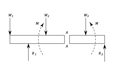
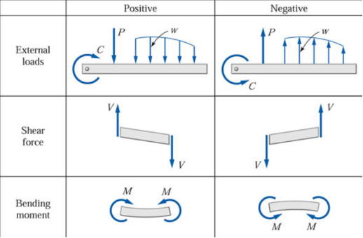
    Table 1- Sign conventions for External loads, Shear force and bending moment

     Q3) Explain the General Guidelines on Construction of SFD and BMD.A3) General Guidelines on Construction of SFD and BMD –Before we go on to solving problems, several standard procedures (or practices) in relation with construction of shear force and bending moment diagrams need to be noted. 1) The load, shear and bending moment diagrams should be constructed one below the other, in that order, all with the same horizontal scale. 2) The dimension on the beam need not be scaled but should be relative and proportionate (a 3 m span length should not look more than 5 m length!). 3) Ordinates (i.e., BM and SF values) need not be plotted to scale but should be relative. Curvature may need to be exaggerated for clarity. 4) Principal ordinates (BM and SF values at salient points) should be labeled on both SFD and BMD. 5) A clear distinction must be made on all straight lines as to whether the line is horizontal or has a positive or negative slope. 6) The entire diagram may be shaded or hatched for clarity, if desired. Q4) Explain the Calculation of maximum SF and BMA4)

    Calculation of maximum SF and BM –

    A)                Maximum Shear Force –

     A beam of rectangular cross-section is subjected to a bending moment M

    (N-m) and a maximum shear force V (N).

    The bending stress in the beam is calculated as

    σ=6M/bd2 (Pa),

    and average shear stress is calculated as

    τ=3V/2bd (Pa),

    where b is the width and d is the depth of the beam.


    B)                Maximum Bending Moment –

    To determine the maximum stress due to bending

    = =

    Where:
  • σmax is the maximum stress at the farthest surface from the neutral axis (it can be top or bottom)
  • M is the bending moment along the length of the beam where the stress is calculated.
  • If the maximum bending stress is required then M is the maximum bending moment acting on the beam
  • Ix is the moment of inertia about x (horizontal) centroidal axis
  • C is the maximum distance from the centroidal axis to the extreme fibre (again, this can be to the top or bottom of the shape)
  • Zx is called section modulus and is a term that combines the moment of inertia and the distance to the extreme fibre (Zx = Ix / c).
  •     Q5) Explain the Uniformly Distributed Load (UDL)A5)

    Uniformly Distributed Load (UDL) –


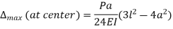
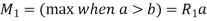
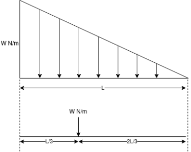
                                       Fig 3.Load act center of VDL

  • There will be parabola in BM and inclined line in SF diagram
  •  Q6) Explain the Two equal concentrated loads at symmetrical placed.A6)

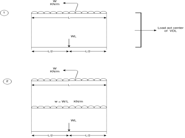
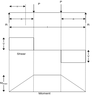
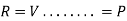
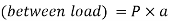
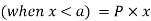
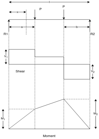
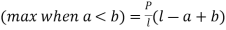
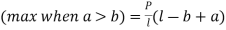
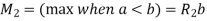
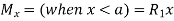
    a)     Two equal concentrated loads at symmetrical placed –


       Fig.4 Two equal concentred loads at symmetrical placed


     Q7) Explain the Two equal concentred loads unsymmetrical placed.A7)Two equal concentred loads unsymmetrical placed

                             Fig.5 Two equal concentred loads unsymmetrical place

     Q8) Explain the Uniformly Varying Load (UVL)A8)Uniformly Varying Load (UVL) –

     Fig.6 Uniformly Varying Load (UVL)Load act at the centroid of the triangular Area
  • There will be a parabola in S.F and B.M.
  • Q9) Explain the Short tricks of SFD and BMD:A9)Short tricks of SFD and BMD:

    Sr.No

    Loading

    Shear force diagram

    Bending Moment diagram

    1

    No Load between two section

    Horizontal line

    Inclined line

    2

    U.D.L between two sections

    Inclined line

    Parabolic curve

    3

    U.V.L between two section

    Parabolic curve

    Cubic curve

    4

    Point load at a point

    Rise or drop at that point

    -

    5

    Couple at a point

    -

    Rise or drop at that point

    6

    Internal hinges

    No effect in S.F.D

    B.M.D is zero

      Q10) What is Point of Contra-flexure?A10)Point of Contra-flexure –
  • It is the point in bending moment diagram where bending moment changes its sign from positive to negative and vice versa.
  • At that point bending moment is equal to zero. This point is called as point of contra-flexure
  •