= V, has to be equal to zero.
|
|
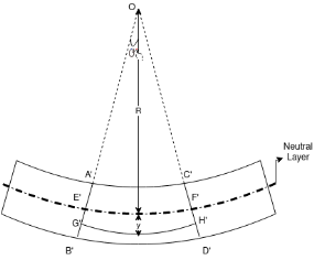
Let A’ B’ and C’ D’ intersect each other at O.
Let, R = Radius of curvature of Neutral layer FF. Θ = Subtended angle at o
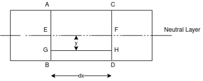
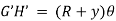
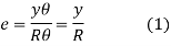
Consider a layer GH at a distance y from Neutral axis Strain in layer GH due to bending
Let GH=EF
From fig-2
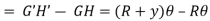
Length of arc = Subtended angle × Radius Original length Length of layer Change in length
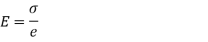
By definition, modulus of elasticity
From Equation (1) and (2)
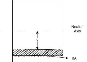
Since E and R are constant, the stress is directly proportional to the distance from Neutral axis. Now consider cross-section of the beam. Consider an elemental strip at ‘y’ from NA and Area of strip ‘dA’. Force on the strip = Stress on the strip × Area on the strip
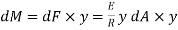
Moment of this force about N.A
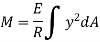
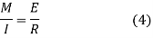
Total moment of whole section about N.A
But
From
This is known as Bending formula or Flexure formula. |


|
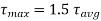
Where
And
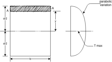
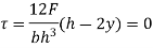
Thus the shear stress variation is parabolic when (i) at (ii) at (iii)
|


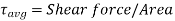
 Width of the element


|
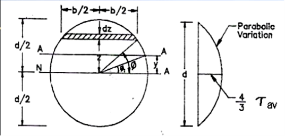
Area of the element
Moment of area of the element about the N.A=A×Z
Therefore moment of the entire area, above the fibre AA about the N.A = a
If
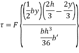
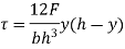
Moment of inertia of the section Substituting in the expression for shear stress
Where b=width of the fibre AA =
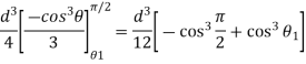
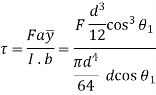
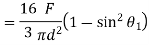
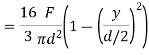
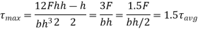
Hence shear stress varies parabolically over the depth. Its value is zero at the extreme fibres where
Thus in circular sections shear stress is maximum at the centre and is equal to 4/3 times the average stress |


|
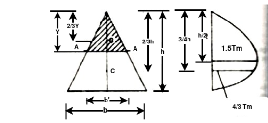
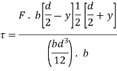
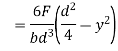
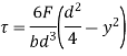
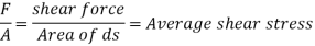
Let AA be a fibre distance y from the top. Shear stress in general
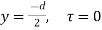
i) at ii) at At the centroid
Or
Thus maximum shear stress occurs at the half the depth and its value is 1.5 times the average shear stress in the case of an isosceles triangle.
|


Determination of Bending Stresses –
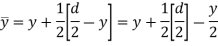
M = Internal bending moment about the section’s neutral axis y = Perpendicular distance from the neutral axis to a point on the section I = Moment of Inertia of the section area about the neutral axis
Where, c = Perpendicular distance from the neutral axis to the farthest point on the section |


To calculate the section modulus, the following formula applies: Z = Where, I = moment of inertia, y = distance from centroid to top or bottom edge of the rectangle For symmetrical sections the value of Z is the same above or below the centroid. For asymmetrical sections, two values are found: Z max and Z min. |


Design of Simple Beam Section – For a simple floor beam, I-sections are used.
M =
Therefore, M = z σ When beams are loaded, bending stresses are developed at all sections. The bending stresses developed in beams can be determined by the equation theory of simple bending. For laterally supported beams, the permissible bending stress in tension as well as in compression should not exceed σbc or σbt = 0.66fy For laterally unsupported beams, the permissible stress in bending compression is calculated by using tables from the IS code book (IS:800). Load carrying capacity of the Beam From structural steel tables for the given beam, the section modulus ( Depending upon whether the beam is laterally restrained or unrestrained; the value of permissible stress in bending compression (σbc) is calculated. The moment of resistance of the beam is found out. MR = Equating the moment of resistance to the maximum bending moment equation, the total load (w) the beam can carry is calculated. |


Torsion equation or torsion constant is defined as the geometrical property of a bar’s cross-section that is involved in the axis of the bar that has a relationship between the angle of twist and applied torque. The SI unit of Torsion equation is m4. The torsion equation is given as follows:
Where, T - torsional moment, N-mm J - polar moment of inertia, mm4 - shear stress in the element, N/mm2 r- distance of element from centre of shaft, mm G - modulus of rigidity, N/mm2 - angle of twist, rad L- length of shaft, mm |

Consider a solid circular shaft with radius R that is subjected to a torque T at one end and the other end under the same torque. Angle in radius = Arc AB = RӨ = Lγ
Where, A and B: two fixed points on the circular shaft γ: angle subtended by AB
Where, 𝞃: shear stress γ: shear strain
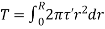
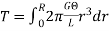
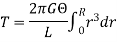
Consider a small strip of radius with thickness dr that is subjected to shear stress.
Where, r: radius of small strip dr: thickness of the strip γ: shear stress
Therefore, this equation is Torsion equation. C) Assumptions Following are the assumptions made for the derivation of torsion equation:
|


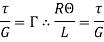


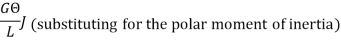

From the torsion equation, Angle of twist,
Where, T - Torsional moment, N-mm J - Polar moment of inertia, mm4 G - Modulus of rigidity, N/mm2 (sometimes denoted by C) - angle of twist, rad For a given specimen, the shaft properties like length L, polar modulus J and material properties like rigidity modulus G are constants and hence the angle of twist is directly proportional to the twisting moment or torque producing the twist. Torque producing twist in a shaft is similar to the bending moment producing bend or deflection in a beam. Similar to the flexural rigidity in beams expressed by EI, torsional rigidity is expressed as GJ which can be defined as the torque required to produce a twist of unit radian per unit length of the shaft. |


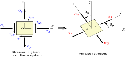
Principal Stress and Maximum Shear Stress A) Principal Stress – There exists an angle qp where the shear stress tx'y' becomes zero. That angle is found by setting tx'y' to zero in the above shear transformation equation and solving for q (set equal to qp). The result is,
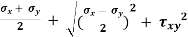
The angle qp defines the principal directions where the only stresses are normal stresses. These stresses are called principal stresses and are found from the original stresses (expressed in the x, y, z directions) via,
The transformation to the principal directions can be illustrated as:
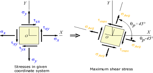
Fig 7. Principal Stress B) Maximum Shear Stress – Another important angle,
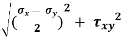
The maximum shear stress is equal to one-half the difference between the two principal stresses,
The transformation to the maximum shear stress direction can be illustrated as:
Fig 8. Maximum Shear Stress Part C) Shear Stresses –
|