Unit - 4
Rolling loads and Influence line diagrams
Q1) Explain rolling loads and influence line diagrams for determinate beams and trusses?
A1)
1. Influence line:
An influence line for a given characteristic, which includes a reaction, axial pressure, shear pressure, or bending moment, is a graph that indicates the version of that characteristic at any given factor on a shape because of the software of a unit load at any factor on the shape. Influence line is additive and scalar. The scaled most and minimal are the essential magnitudes that need to be designed for within side the beam or truss.
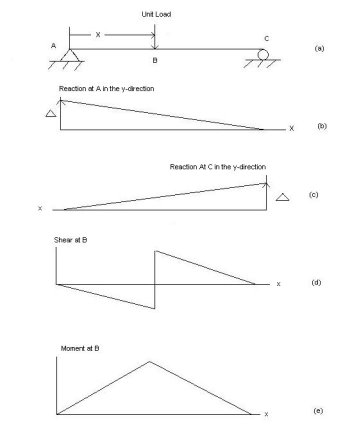
Examples:
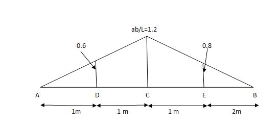
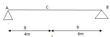
1] A simply supported beam is subjected to loads as shown in fig.
Using influence lines find
Support reactions
Shear force & bending moment at ‘C’
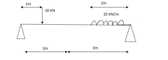
Solution:
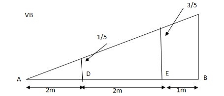
1) VA&VB
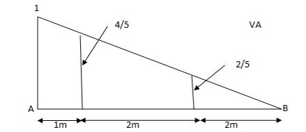
VA=20+251=16+10=26KN
VB=20+25+=4+40=44KN
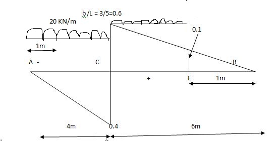
=0.6
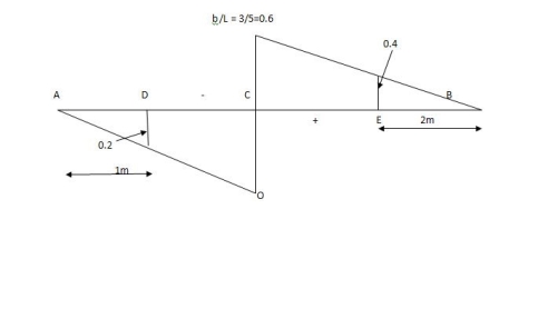
SF @c=20(-0.2) +25=5KN
BM @c=20(0.6) +(20.8) (25) =32KN.M
2. Rolling loads:
Loads which roll over the given structural detail from one quit to the every other quit. In a rolling load most shears force, bending moments.
Example: Train on the railway track, automobiles at the bridges or roads are rolling loads etc.
Rolling loads there are 3 types:
1. Single factor rolling load
2. Uniformly distributed load
3. Two factor rolling load
Uniformlydistributedloadtherearemaintypes:1) Longer than span 2) Smaller than span
ILD for beams and rolling load:
It is a diagram which shows version of AF, SF and BM on the sort of characteristic at a unique section for numerous function of moving load.
It is a diagram which indicates variation of AF, SF and BM on any such function at a particular section for various position of moving load.
AFD, SFD, BMD ILD
Load position fixed (for particular%)
How to find value of function from ILD
i) Structure subjected to point loads

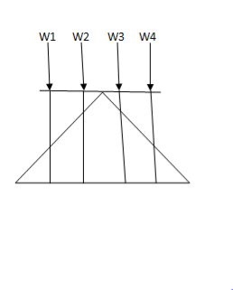
Meg. Of function=W1Y1+W2Y2+W3Y3+W4Y4
Ii) Structure subjected to udl
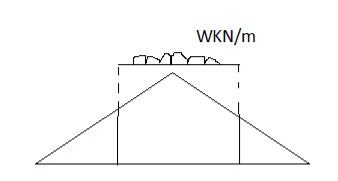
Magnitude of function= {Area of ILD under UDL}𝓌
i)VA=? (ii)MA=?(iii)SF=(iv)BM=
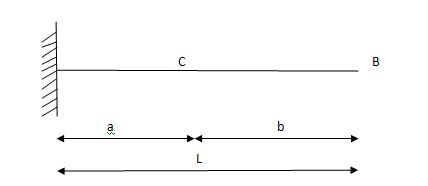
1) ILD’s for VA & MA
Consider unit load at a distance
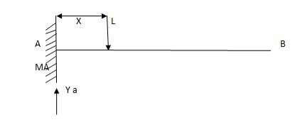
MA=MA-1(x)=0
MA=x
X VA MA
0 1 0
L 1 0
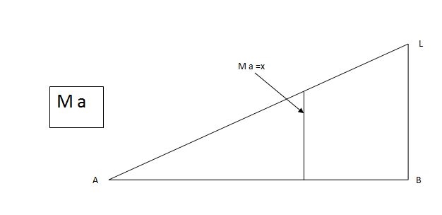
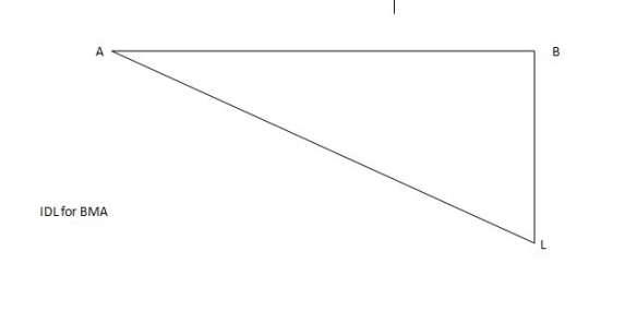
ILD for bending moment at A is as below
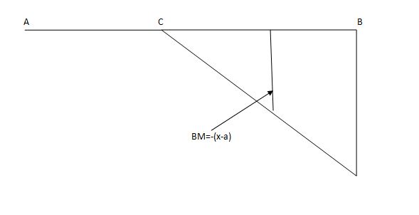
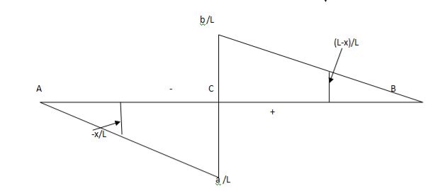
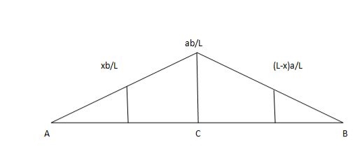
ILD for shear force & BM at ‘C’

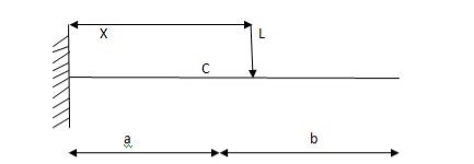
SF @c=0, BMC=0
SFC=1; BMC=-1(x-a)
For x=a; BM@ c=0X=L;
BMC=-1(1-a) cb
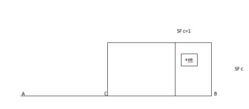
2)
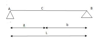
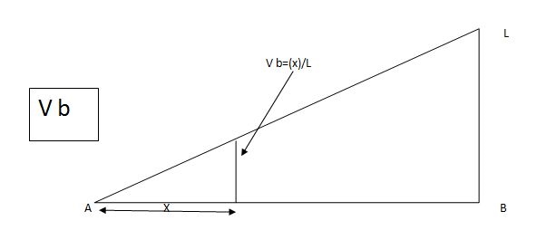
1)ILD’s for VA&VB
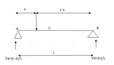
x VA VB
0 1 0
L 0 1
2) SF c & BM c
1)
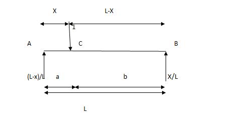
2)
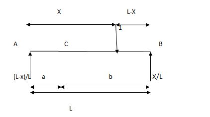
Example:
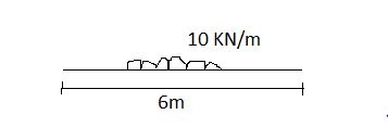
1]A simply supported beam subjected to moving udl
Solution:
1)
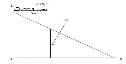
VA max= (20)=75KN
VA max=20=75KN
Note: Absolute maximum shear force is nothing but greater 07VA, max & VB, max
Abs. Max SF=75KN
2)
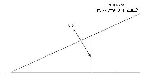
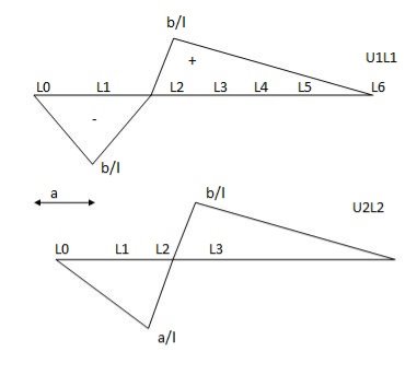
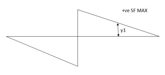
Max.(–ve) SFc= (-)(20)
=()16KN
Max. +ve SF =35KN
Max. SF c=35KN
Note:
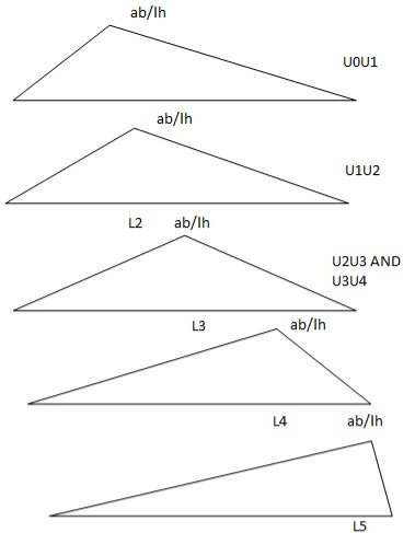
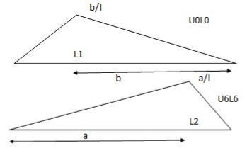
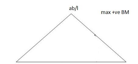
When length of udl is smaller than bas of triangle, placed udl such that load pera on LH& RHS of height of triangle is same.
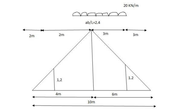
x=2m
= (5)(20) =180KNm
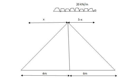
Abs. Max BM= (5)(20) =187.5KNm
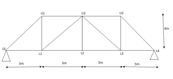
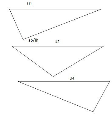
Diagonal members design
Top camp
Q2) What is absolute maximum bending moment and shear force?
A2)
A. Maximum Bending moment:
Consider a section x-x at the distance x- from left support
∑ (BM)XX = WL/2. X- (W.X) X/2 = WL/2 = WX2/2
Bending moment equation shows that BM curve is parabolic
At x=0 BMA = 0
At X= L BMB = WL/2 X L – WL2/2 = 0
Position and magnitude of maximum BM
Maximum bending moment occurs where shear force is zero.
Now location of point where SF = 0
∑ (SF) XX = 0
WL/2 – WX = 0
Therefore x= L/2
Bending moment at x = L/2
BM = WL/2 (L/2) – W/2 (L/2)2 = WL/4-WL2/8


B. Maximum Shear force calculation:
Consider a section x-x at the distance X from A
∑ (SF)XX = WL/2 –WX
At x = 0, SFA = WL/2
At x= L, SFB = WL/2- WL = -WL/2

Q3) A simply supported beam of span L is carrying uniformly distributed load w over its entire span calculate S.F. And B.M. Also draw SFD and BMD.
A3)

1. Support reaction:
Since the beam is subjected to the symmetrical loading support reactions is half of the total load

2. Shear force calculation:
Consider a section x-x at the distance X from A
∑ (SF)XX = WL/2 –WX
At x = 0, SFA = WL/2
At x= L, SFB = WL/2- WL = -WL/2
3. Bending moment:
Consider a section x-x at the distance x- from left support
∑ (BM)XX = WL/2. X- (W.X) X/2 = WL/2 = WX2/2
Bending moment equation shows that BM curve is parabolic
At x=0 BMA = 0
At X= L BMB = WL/2 X L – WL2/2 = 0
Position and magnitude of maximum BM
Maximum bending moment occurs where shear force is zero.
Now location of point where SF = 0
∑ (SF) XX = 0
WL/2 – WX = 0
Therefore x= L/2
Bending moment at x = L/2
BM = WL/2 (L/2) – W/2 (L/2)2 = WL/4-WL2/8

Q4) Explain Muller-Breslau’s principal & its applications for determinate structures?
A4) Muller- Breslau principle:
Influence liens for simply supported beam

Find reactions at support, S.F.& B.M. At a section _______ at A RA=?
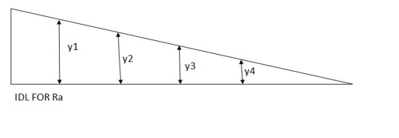
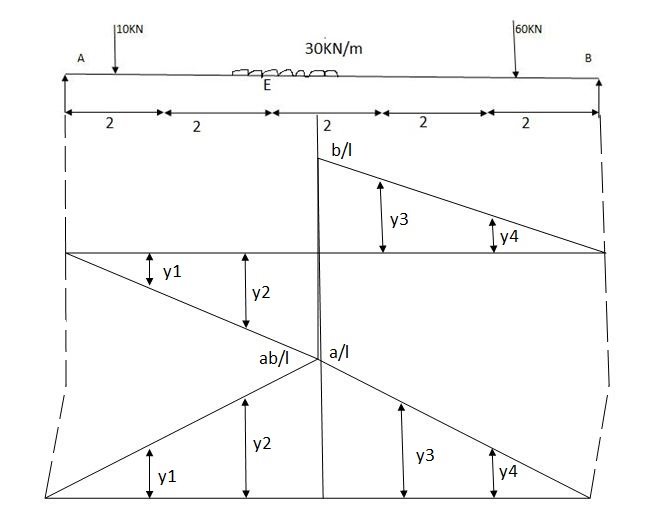
10 y1 +  2 30 + 60 y4
 =
=  y1 =0.8
  =
=  y3=0.4
 =
=  y2 =0.6
  =
=  y4=0.2
RA = 10 0.8 +  2 30 + 60 0.2
RA =KN
RB= 10 y1 +  30 2 + 60 y4
 =
=  y1 =0.2
  =
=  y3=0.6
 =
=  y2 =0.4
  =
=  y4=0.8
RB = 10 0.2 +  2 30 + 60 0.2
RA = 62 KN
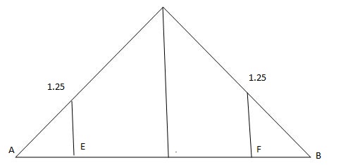
Near for at E
 =
=  = 0.5
= 0.5  =
=  y3
y3
 =
=  = 0.5
= 0.5  =
=  y4
y4
 =
=  y2
y2  =
=  y1
y1
At E = 10 y1 +30 1 + 30 1
  + 60 y4
At E = 8 KN
-ve S.F.at E = 10 -y1 + 30 1 
 =
=  =
=  =2.5
=2.5
 =
=
 =
= =
=
 =
= y2
y2 =
=
B.M. At E = 10 y1 + 30 1  +30 1 + 60 y4
Find the position of loads to get max-ve S.F. Of B.M.
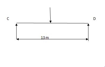
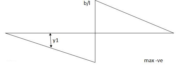
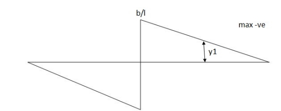
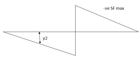
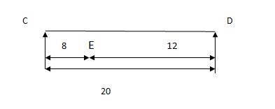
Two wheel loads of 80 KN & 100 KN at 3 m find max.m the S.F. & maxm -ve S.F. And B.M. At 5 m from left
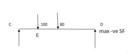
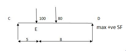
Q5) What is application of determinate structure?
A5)
A simply supported beam is subjected to loads as shown in fig. using influence lines find
- Support reactions
- Shear force & bending moment at ‘C’
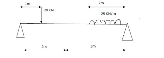
1) VA& VB
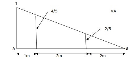
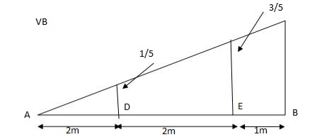
VA = 20 + 25 1
 = 16 + 10 = 26 KN
VB = 20  + 25
+ 25  +
+  = 4 + 40 = 44 KN

 =
=  =0.6
=0.6
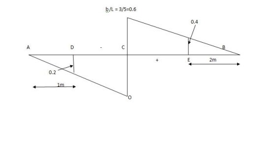
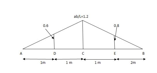
SFc = 20 (-0.2) + 25= 5KN
BMc = 20 (0.6) +  (2 0.8) (25)
= 32 KN/M.