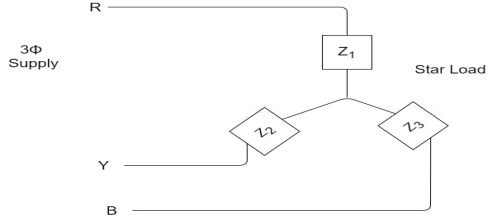
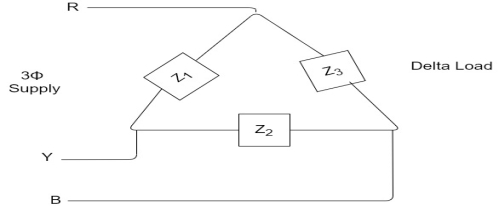
1. Calculate VPh from the given value of VL by relation For star VPh = For delta VPh = VL
2. Calculate IPh using formula IPh =
3. Calculate IL using relation
IL = IPh - for star
IL =
4. Calculate P by formula (active power)
P =
5. Calculate Q by formula (reactive power)
Q =
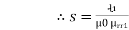
6. Calculate S by formula (Apparent power)
S = |


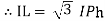
3Φ system in which three voltages are of identical magnitudes and frequency and are displaced by 120° from each other called as symmetrical system. Phase sequence: The sequence in which the three phases reach their maximum positive values. Sequence is R-Y-B. Three colours used to denote three faces are red ,yellow and blue. The direction of rotation of 3Φ machines depends on phase sequence. If a sequence is changed i.e. R-B-Y then the direction of rotation will be reversed. Types of loads
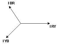
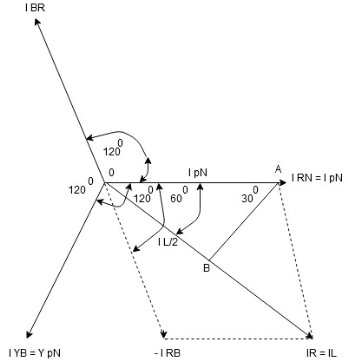
Balanced load: Balanced load is that in which magnitudes of all impedances connected in the load are are equal and the phase angles of them are also equal. i.e. If. Phasor Diagram Consider equation ① Note: we are getting resultant line current IR by subtracting 2 phase currents IRY and IBR
Cos 300 =
Phase current IYB lags behind VYB which is phase voltage as the load is inductive |


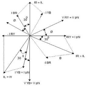
In a series resonant circuit, the resonant frequency, ƒr point can be calculated as follows. XL = Xc --- 2 π f L = 1/ 2 π f C f 2 = 1/ 2 π L x 2 π C = 1/ 4 π 2 L C f = [1/ 4 π 2 L C ] ½ fr = 1/ 2 π
In the circuit high quality factor is required to ensure low energy dissipation and low oscillation damping but high-quality factor can only be achieved by bandwidth. Therefore, it is required to maintain balance between these two Q = fr/BW Fr = 1/ 2 π Q = 1/R BW = R/L |
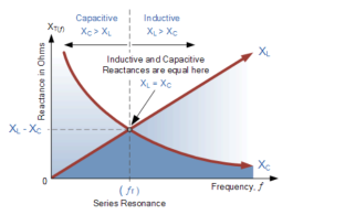


In series magnetic circuit flux Consider a composite magnetic circuit made from different material of lengths ɻ1,ɻ2, and ɻ3 cross sectional area a1, a2 And a3 and relative permeability’s
We know that S =
But S =
Now B =
but B=μH
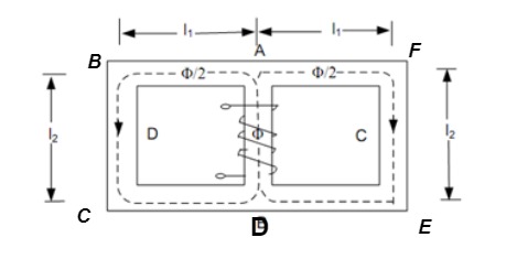
A magnetic circuit which has more than one path for flux called parallel magnetic circuit
Mean length ABCDA = ɻ₁, and ADEFA = ɻ₂ Mean length path for central limb = ɻc Reluctance ABCDA = S1, ADEFA = S2 And central limb = SC Now total mmȴ = N
For path ABC AD N Where S1 = Where
Total mmȴ = mmȴ by central limb + mmȴ required by any one of outer limb = Ø sc + [Ø1S1 or Ø2 S2] As mmf across parallel branch is same
Hence while calculating total mmf, the mmf of only one of 2 parallel branches must be considered. |


S= V × I Unit - Volte- Ampere (VA) In kilo – KVA
2. Real power/ True power/Active power/Useful power: (P) it is defined as the product of rms value of voltage and current and the active component or it is the average or actual power consumed by the resistive path (R) in the given combinational circuit. It is measured in watts P = VI 3. Reactive power/Imaginary/useless power [Q] It is defined as the product of voltage, current and sine B and I Therefore, Q= V.I Unit –VA R In kilo- KVAR Represent Sinusoidal waveforms – Average and effective values.
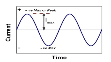
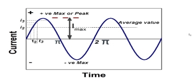
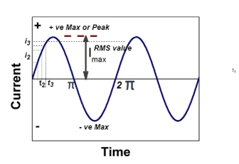
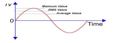
Peat to peak value: The value of an alternating quantity from its positive peak to negative peak
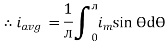
Average Value:
The arithmetic mean of all the value over complete one cycle is called as average value
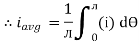
For the derivation we are considering only hall cycle. Thus i = Im Sin
Solving We get
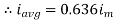
Similarly, Vavg= The average value of sinusoid ally varying alternating current is 0.636 times maximum value of alternating current. |


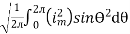
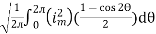
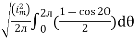
The RMS value of AC current is equal to the steady state DC current that required to produce the same amount of heat produced by ac current provided that resistance and time for which these currents flows are identical.
I rms =
Direction for RMS value: Instantaneous current equation is given by i = Im Sin but I rms = = = = Solving = = Similar we can derive V rms=
|


It is the ratio of maximum value to rms value of given alternating quantity Kp =
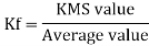
Form factor (Kf): For numerical “It is the ratio of RMS value to average value of given alternating quality”.
|


The instantaneous voltage equation V(t) = V m sin (w t + Ø)
The instantaneous voltage equation is given by Vt= vm sin (w t +Ø) which can be represented by polar form vt = where e.g. vt =30 sin (w t + 90 polar form polar form is suitable for multiplication and division of phases. 2. Rectangular Form: The instantaneous voltage equation is given by Vt = v m sin (w t +Ø) which can be represented by Rectangular Form vt = where X = Y = Vt = v m cos Ø + i vm sin Ø e.g. 30 sin (w t + 90) Rectangular form vt = 30 cos 90 + i 30 sin 90
Trigonometric Form (Polar to Rectangular) If the phases are given in polar form from rectangular form by expressing X and Y component in form of Polar: Vt = Rectangular: vt= 𝑥 = 𝑦 =
Exponential Form (R-P) Given equation Rect : v(+) =𝑥 + i𝑦 Polar: v(+) = Where magnetite And 2 Phase added and substrate using Rect. Form Let V1 = 𝑥1 + i𝑦1 V2 = 𝑥2 + i𝑦2
= (𝑥1 + 𝑥2) + i(𝑦1 + 𝑦2) (V1 – V2) = (𝑥1 – 𝑥2) + i(𝑦1 - 𝑦2) For add or subst. If eqtn. Is given in polar form, we have to connect into Rect. Form and then add/ subtract. Two phases divide/ multiply by polar Let V1 = π1 L Ø1 Let V2 = π2 L Ø2 (V1 V2) = (π1 L Ø1) (π2 L Ø2)
For dividing
|


Reactance
It is opposition to the flow of an AC current offered by inductor. XL = ω L But ω = 2 ᴫ F
It is measured in ohm
2. Capacitive Reactance (Xc) It is opposition to the flow of ac current offered by capacitor Xc = Measured in ohm
Impedance (Z) The ac circuit is to always pure R pure L and pure C it well attains the combination of these elements. “The combination of R1 XL and XC is defined and called as impedance represented as Z = R +i X Ø = 0
R = Resistance, i = denoted complex variable, X =Reactance XL or Xc |


