Back to Study material
BEE

Unit – 5Electrical Installations Q1) Explain the working principle of Fuse.A1)


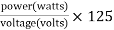
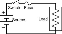
The working principle of the fuse is “ heating consequence of the current”. It is fabricated with a lean strip for thread of metallic wire. The connection of the fuse in an electrical circuit is always in series. When the too much current is produced due to the heavy flow of current in the electrical circuit the fuse get soft and it opens the circuit. The extreme flow of current main direct to the collapse of the wires and prevents the supply. Diffuse can be changed by the new fuse with an appropriate rating. It can be designed with elements like copper, zinc, aluminium and silver. They also perform like a circuit breaker for breaking the circuit while the abrupt fault happens in the circuit. This works like a safety measure for protector for humans from risk. Like this, the fuse works

Fuse rating =

The selection of a fuse can be done by calculating the fuse rating by using the above formula

  • Write down the voltage (volts) and power (watts) of the appliance.
  • Calculate the fuse rating.
  • After the result use the maximum fuse rating. For instance, if the calculated fuse rating is the maximum fuse rating. For example, if the calculated fuse rating is 7.689 amps, you can use an 8 amp fuse.
  Q2) Write and explain different types of Fuses.
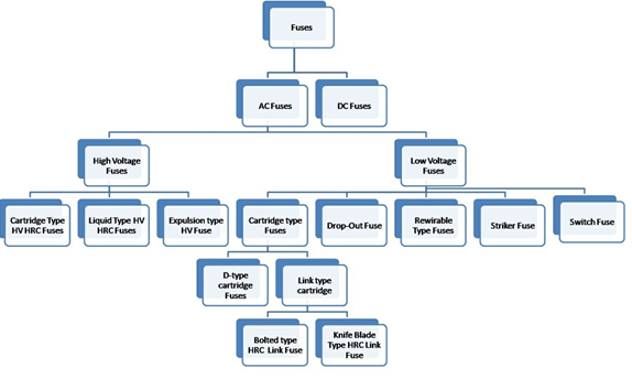
A2)

The fuses are classified into to several types based on the application namely AC type fuse and DC type fuse. Again these fuses are classified into several types. The following diagram illustrates the electrical fuse types chart based on the AC fuse and DC fuse.


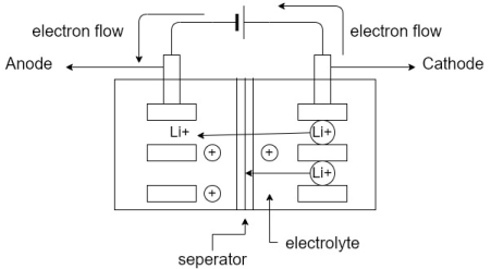
DC fuse:

DC fuses are available superior in size and DC supply has a stable value over 0 volts. So it is tough to remove and deactivate the circuit. There will be a chance of generation of electrical Arc between dissolved wires. To conquer this electrodes located at battery distances. For this reason the size of the DC fuse gets amplified.


AC fuses:

The AC fuse is lighter in size and oscillated 50 to 60 times in each and every second from least to highest. As a result, there is no scope for Arc generation between the dissolved wires. For this reason, they can be crammed into a small size. Further, AC fuses are classified into two parts namely HV fuses and LV fuses. Here LV and HV indicates the low voltage and high voltage LV fuses. The low voltage fuses are divided into five types such as rewirable, cartridge, dropout, striker and switch fuses.
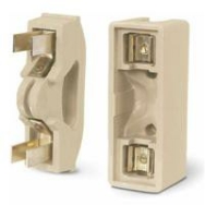
 

Rewirable fuses:


Rewirable fuses are LV fuses, which are almost used in small applications like wiring in in the house, small scale industries, and other tiny current applications. these types of fuses include two essential parts such as a fuse base which has two terminals like in and out. In general, this element is fabricated with porcelain. Another part of this fuse is a fuse carrier, which grip the fuse element. This element is fabricated with aluminium, tinned copper and lead. The main advantage of a fuse carrier is, we can simply plug and remove from the base of the fuse without the risk of shock. As the fuse is damaged due to heavy current, then we can simply eliminate the fuse carrier as well as put back the fuse wire.


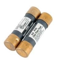
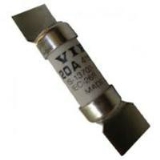
Cartridge type fuses:


The cartridge type of fuses has entirely closed containers and the metal contact as well. The applications of this fuses mainly include low voltage (LV), high voltage (HV) and small fuses. again this types of fuses are classified into two types, they are D type and link type fuses.


D type Cartridge Fuse


This type of fuse is composed with the cartridge, base of the fuse, adapt or ring, and cap. The base of the fuse includes a fuse cap, which is packed with the fuse ingredient by cartridge using an adapter ring. It is composed of the cartridge, fuse base, cap and adaptor ring. The fuse base has the fuse cap, which is fitted with the fuse element with a cartridge through the adaptor ring. The connection of the circuit is finished when the tilt of the cartridge builts contact through the conductor.


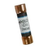
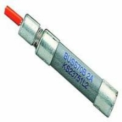
High Rupturing capacity or Link Type Fuse:


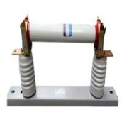
The link type fuse is also known as high rupturing capacity (HRC) or BS type fuse. In this sort of fuse, the current flow with fuse element is specified under standard condition in this BS type fuse, the flow of current by fuse element is given under normal condition. The arc which is generated by the fuse blown is controlled is fabricated with porcelain, ceramic and silver. the container of the fuse element is packed with silica sand. This type of use is again characterized into two parts includes a blade type and bolted type.


Blade and bolted type fuses


The knife type fuse for plugin type of fuses are designed with plastic. this type of use can be simply changeable in the electric current exclusive of any load in bolted type fuse, plates of this fuse are conducting are set to the base of the fuse.


Striker type fuse


Describe the type of fuse is employed for tripping and closing the electrical circuit. This fuses are having plenty of force as well as displacement.
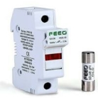
 

Switch type fuse


Basically the switch type fuse is enclosed with a metal switch and also a fuse. These fuses are mainly used in low and intermediate voltage levels.


HV (High voltage) Fuses


Generally, HV fuses are used to protect the transformers like instrument transformers, small Power transformer and also used in power systems. These fuses are normally charged for voltages over 1500 volt to 138000 volte.

The fuse part in HV fuses are fabricated with either copper, silver or in some cases tin is used, in order to offer consistent and steady performance. These fuses are classified into three types which include the following.


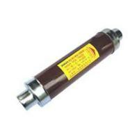
Cartridge type HRC fuse

The fuse component of the HRC is cut in The helix form which evades the effect of the corona at the upper voltages. It includes to fuse elements namely low resistance and high resistance, and that are located parallel by each other. The low resistance wires take the usual current which is is blown out as well as decreases the short circuit current throughout the fault state.


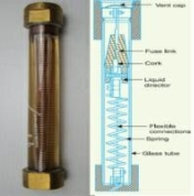
Liquid type HRC fuse


This type of fuse is packed with carbon tetrachloride also preserved at both the tops of the caps. Once the error occurs when the following current surpasses away from the allowable limit and the element of the fuse is blown out. the flute of the fuse performs as an Arc extinguishing standard for the HRC fuse types. they may be used to protect the transformer as well as the support protection to the breaker circuit.


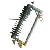
Expulsion type HV fuse

These types of fuses are extensively used to protect the feeders as well as transformer due to they're low priced. It is designed for 11kV, also their cracking capability is up to 250 MVA. This type of use includes and unfilled open finished cylinder designed with synthetic resin bonded paper. The elements of the fuse are positioned in the cylinder, and the tops of the tubes are linked to appropriate equipment at every finish. The ark generating is blown off in the inside covering of the cylinder, and gases thus shaved destroys the arc.

 Q3) Write a short note on: Miniature Circuit Breaker.A3) Miniature Circuit breakers (MCB) are electromechanical devices which are used to protect electrical equipment from an over current. MCB is a a mechanical switching device which is capable of making, caring and breaking currents under normal circuit conditions and also making, caring for a specified time and automatically breaking currents under specified abnormal circuit conditions such as those of short circuit. In short MCB is a device for over load and short circuit protection.

 A) Construction :- The construction of miniature circuit breakers is very simple, robust and maintenance free. MCB is replaced by a new one when it is failing because MCB is not repaired or maintained. There are three types of miniature circuit breakers in construction,1) Frame:- Frame is a rigid, strong, insulated housing in which the other components are mounted. It is a moulded case.2) Trip unit : For the proper working of the miniature circuit breaker trip unit is responsible. Two main types of trip mechanism are provided in Miniature circuit breaker (MCB). a bimetallic strip provides protection against overload current and an electromagnet provides protection against short circuit current. Trip unit is the main part of the MCB.3) Operating Mechanism:-  The operating mechanism of MCB provides with the manual operation for closing and opening operation of the miniature circuit breaker. It has three positions “ON”, “OFF”, “TRIPPED”. By observing the position of the switching latch one can determine the condition of MCB whether it is closed, tripped or manually switched off. If the MCB is tripped due to overcurrent or overheating. The external switching latch in the “TRIPPED” position. When manually switch off the miniature circuit breaker, the switching latch will be in “OFF” position. The switch is positioned at “ON”, in a closed condition of the miniature circuit breaker. Q4) What are the different types of MCB?A4)

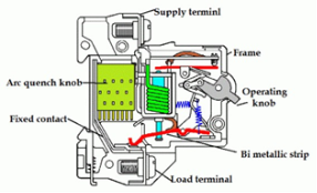
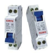
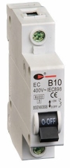
There are three standard characteristics are available for domestic as well as commercial MCB are given by B,C and D. Each type has its own function

Type B


MCB are mainly used where switching surges are small or non exist and are generally suitable for domestic applications and light commercial applications. There are no devices with long high starting current in domestic applications and has the best suited MCB is type B. these are designed to trip at fault currents in the range of 3 to 5 times the rated current. Suppose if the rated current is 10 ampere then the MCB trips at 30-50 A.

Type C


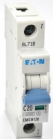
MCB are designed for high inductive circuits where surge currents are expected. These are generally used for commercial and industrial applications where a number of fluorescent lamps been turned ON or starting of small motors may give high search currents.

These are more sensitive than type B MCB and causes reduced nuisance trips. Type C MCB are designed to operate for trip at the fault currents of 5 to 10 times that of rated current. For 10 A type C MCB, the operating current range is 50 – 100 A.

Type D

MCBs are designed for heavy industrial applications where normal surge currents are very high. These are ideal for electrical welders and site Transformers where frequent high surge currents are expected.

The most common applications of type D MCBs include motors, UPS systems comma x-ray machines, Transformers and battery charging systems. These are designed to trip at 10 – 20 times The rated current. For 10 A type D MCBs, the operating current range is 100 – 200 A.

The setting or characteristics of an MCP are fixed in the factory itself by the manufacturer and they are not adjustable at the user end or at the site. Tripping currents for operation at 0.1 second or less different MCBs are given below.

Type B

3-5 times rated current

Type C

5-10 times rated current

Type D

10-20 times rated current

 Q5) Explain Earth Leakage Circuit Breaker (ELCB).A5) An ECLB is one kind of safety device used for installing an electric device with high Earth impedance to avoid shock. These devices is identify small stray voltages of the the electrical device on the metal enclosures and intrude the circuit if a dangerous voltage is identified. The main purpose of Earth leakage circuit breaker is to stop damage to humans and animals due to electric shock. Earth leakage circuit breaker is a device used to directly detect currents leakage to earth from an installation and cut the power and mainly used in TT earthing systems.There are two types of ELCBs :1) Voltage Earth leakage Circuit Breaker (voltage ELCB)2) Current Earth Leakage Circuit System (Current ELCB)Voltage ELCB have first introduced about 60 years ago and current ELCB was first introduced about 40 years ago. For many years, the voltage operated ELCB and the differential current operated ELCB were both are referred to as ELCB because it was a simpler name to remember. But the use of a common name for two different devices gave rise to.Considerable confusion in the electrical industry. If the wrong type was used on an installation, the level of protection given could be substantially less than that intended. To ignore this confusion, IEC decided to apply the term residual current devices (RCD) two differential current operated ELCBs. Residual current refers to any current over and above the load current. Q6) Write and explain working principle of Voltage ELCBA6)

 ELCB is a voltage operated device. It has a coil and if the voltage across the coil exceeds as a predetermined value such as 50 V, the current through the coil will be sufficient enough to trip the circuit. Voltage ELCB is connected in between the metallic part of equipment and the Earth. If we take an example of insulation failure then the voltage across the coil of voltage ELCB will drive enough Karan to cut the power supply till the manually reset. The way to identify an ELCB is by looking for green or green and yellow Earth wire entering the device. They relay on voltage returning to the trip via the earth wire during a fault and effort only limited protection to the installation and no personal protection at all. You should use plugin 30 mA RCD's for any appliances and extension leads that may be used outside as a minimum. Q7) Explain Moulded Case Circuit Breaker in detail.A7)

 Melded Case Circuit Breaker are electromechanical devices which protect a circuit from overcurrent and short circuit. They provide overcurrent and short circuit protection for circuits ranging from 63 Amps up to 3000 Amps. Their primary functions are to provide a means to manually open a circuit and automatically open a circuit under overload or short circuit conditions. The overcurrent, in an electrical circuit result from short circuit overload for faulty design.Unlike fuse, and MCCB can be easily reset after of faulty and offers improved operational safety and convenience without incurring operating cost.Moulded case circuit breakers generally have a thermal element for overcurrent and magnetic element for short current release which has to operate faster. MCCBs are manufactured such that end user will not have access to internal workings of the overcurrent protection device. Generally constructed of two pieces of heavy duty electrically insulated plastic, these two halves are riveted together to form the whole point inside the plastic shell in a series of thermal elements and a spring loaded trigger point when the thermal element gets too warm from an over current situation, the spring strips, which in turn will shut off the electrical circuit. Q8) Compare various types of MCCB.A8)

Types of MCCB

Operating current

Operating time

Application

Suitability

Surge current

Installation location

Type B

Trips between 3 and 5 times rated current (In)

0.04 – 13 seconds

Domestic applications (lighting and resistive elements)

Resistive load application

Low

Sub feeder of distribution board

Type C

Trips between 5 and 10 times rated current (In)

0.04 – 5 seconds

Commercial or industrial applications

Inductive load applications

Moderate

At incoming/outgoing of distribution board

Type D

Trips between 10 to 20 times rated current (In)

0.04 – 3 seconds

Commercial or industrial applications

Inductive capacitive load applications (pumps, motor, large winding motors e.t.c.)

High

At incoming of distribution board/panels

Type K

Trips between 8 to 12 times rated current (In)

 0.04 – 5 seconds

Industrial applications

Inductive and motor loads with high in rush currents

High

At incoming of distribution board/panels

Type Z

Trips between 2 to 3 times rated current (In)

0.04 – 5 seconds

Highly sensitive to short circuit and are used for protection of highly sensitive devices such as semiconductor or devices

Medical instruments

Very low

At sub feeder of of distribution board for IT equipment

 Q9) Write a short note on: PVC and lead alloy sheath wiresA9) P.V.C This is the most commonly used for wiring purpose. The conductor is insulated by poly vinyl chloride It has the following properties:Moisture proof Tough Durable Chemically inert It softens at high temperatures therefore it is not suitable for connection to heating appliances. Lead alloy sheathed wires:The ordinary wires can be used only at dry places but for damp places these wires are covered with continuous lead sheaths. The layer of lead covering is very thin like 0.12cm thick. These wires provides mechanical protection to the wires.  Q10) Write and explain types of cables. A10) The types of cables basically decided based on the voltage level for which it is manufactured and material used for the insulation such as paper, cotton, rubber etc. the classification of cables according to the voltage levels is,  Low Tension Cables (L.T. Cables). Medium and High- tension Cables (H.T. Cables).

 BELTED CABLES. These cables are used for the voltage level up to 11 kV. The construction of belted cable is is shown in fig. The cores are not in circular shape. The cores are insulated from each other by use of impregnated paper. The gaps are filled with fibrous material like jute. The belt is covered with lead sheath.

SCREENED TYPE CABLES.These cables are used for the voltage levels of 22 kV. The two types of screened cables are: H-Type cables. S.L. Type cables.H-Type cables. Designed by M. Hochstetler and hence named H-type cable. No paper belt in this type of cable. Each conductor is insulated with a paper, covered with a metallic screen.S.L. Cables. S.L. leads for Separate Lead Screened Cables. Each lead is insulated with an impregnated paper than covered by separate sheath lead.SUPER TENSION (S.T.) CABLES. The S.T. cables are intended for 132 kV to 25 kV voltage levels. In such cables, the following methods are specially used to eliminate the possibility of void formation: Instead of solid type insulation, low viscosity oils under pressure is used for impregnation. Using inert gas at high pressure in b/w the lead sheath & dielectric.OIL FILLED CABLES In case of oil filled cables, the channels or ducts are provided within or adjacent to the cores, through which oil under pressure is circulated. It consists of concentric standard conductor but built around a hallow cylindrical steel spiral core, which acts as a channel for oil.GAS PRESSURE CABLES An inert gas like N at high pressure is introduced lead sheath and dielectric. Gas like SF6 is also used in cables. Pressure is about 12-15 atmosphere. Working power factors is also high. Q11) Explain the importance of earthling.A11) The system of connecting the metal casing of an electrical appliance to a copper plate buried deep inside the earth is called as earthling. Many appliances such as an electric heater, a toaster, an oven, a refrigerator etc. have a metallic body (casing). If with use the insulation of a wire breaks or melts, the live wire may touch the metal casing. If we happen to touch the casing carrying a current, we may receive a severe shock which may cause death. To avoid this, metal casings of all electrical appliances are earthed. One end of a thick copper wire is connected to the metal casing of the appliance and the other end is connected to a copper plate buried deep inside the earth. The current through the metal casing then flows to the earth and the person touching the casing is saved.  Q12) Compare Primary and secondary cells.A12)

Primary

Secondary

Electrical energy indirectly obtained from chemical energy.

Electrical energy is already present in the cell in form of chemical energy and then converted to electrical energy.

Chemical reactions are irreversible (cannot be recharged)

Chemical reactions are reversible.

Cell is replaced when it goes down.

Cell is recharged back.

Polarisation is present.

Polarization is absent.

Low efficiency.

High efficiency.

Capacity is low.

Capacity is high

Less cost

High initial cost.

No maintenance is required.

Frequent charging and other maintenance is required.

 Q13) Draw and explain Lithium ion battery.A13)The lithium ion battery works on the principle of movement of lithium ions from electrodes.Construction
  • The lithium ion battery is made up of an anode cathode, separator, electrolyte and to current collectors (+ve and -ve)
  • Anode-> lithium ion uses carbon electrode as its anode with a current collector of thin copper foil.Cathode -> it uses lithium cobalt oxide commonly used for cathode with the current collector made up of thin aluminium foil.Separator-> a separator is a fine porous polymer film.Electrolyte-> it is the solution based on a lithium salt in an organic solvent.Both electrodes are made up of materials which can “intercalote” or “absorb” the lithium ions. 

     Working
  • Lithium ions are inserted in cathode.
  • For charging the battery is connected to an external power supply.
  • Due to this oxidation occurs at the cathode and it loses electrons which are negatively charged.
  • to maintain the charge balance in the cathode equal number of lithium ions are already dissolved in electrolyte solution.
  • The lithium ion travel through electrolyte and reach to anode.
  • The separator use does not allow the electrons to flow through an electrolyte. The electrons travel through the external wire and reach to anode from cathode.
  • At cathode the electrons get tied with lithium ions.
  • At time of discharging the opposite reactions occur
  • Anode releases electrons and ions.
  • Ions get dissolved in electrolyte and electrons travel from cathode to anode through external circuit.
  • Due to flow of electrons from the external circuit the current is established and device connected to battery is operated.
  • When the cathode is full of lithium ions discharging stops and battery needs to be recharged again.
  •