Unit - 1
Introduction to Mechanics of Solid
Q1) Explain the Normal and shear Stress, strain
A1) a) Normal Stress –
b) Normal Strain –
a) Shear Stress –
The shear stress is defined to be the ratio of the tangential force to the cross-sectional area of the surface upon which it acts,
 = F tan / A
b) Shear Strain –
The shear strain is defined to be the ratio of the horizontal displacement to the height of the block,
α = δ x / h
Q2) Explain the Hookes’ law
A2)
Q3) Explain the Poisson’s ratio
A3) In mechanics, Poisson’s ratio is the negative of the ratio of transverse strain to lateral or axial strain. It is named after Simeon Poisson and denoted by the Greek letter ‘nu’. It is the ratio of the amount of transversal expansion to the amount of axial compression for small values of these changes.
What is Poisson’s Ratio?
Poisson’s ratio is “the ratio of transverse contraction strain to longitudinal extension strain in the direction of the stretching force.” Here,
v = - d  trans / d
  axial
axial
v = resulting Poisson’s ratio
 trans = transverse strain
 axial = axial strain
Q4) What are the Elastic constants
A4) When an elastic body is subjected to stress, a proportionate amount of strain is produced. The ratio of the applied stresses to the strains generated will always be constant and is known as elastic constant. Elastic constant represents the elastic behaviour of objects.
Different elastic constants are as follows:
Q5) Explain the different type of electric constant
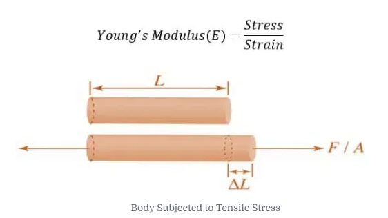
A5) Young’s Modulus
According to Hooke’s law, when a body is subjected to tensile stress or compressive stress, the stress applied is directly proportional to the strain within the elastic limits of that body. The ratio of applied stress to the strain is constant and is known as Young’s modulus or modulus of elasticity.
Young’s modulus is denoted by letter “E”. The unit of modulus of elasticity is the same as the unit of stress which is megapascal (Mpa). 1 Mpa is equal to 1 N/mm2.
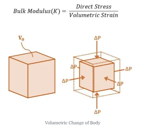
Bulk Modulus
When a body is subjected to mutually perpendicular direct stresses which are alike and equal, within its elastic limits, the ratio of direct stress to the corresponding volumetric strain is found to be constant. This ratio is called bulk modulus and is represented by letter “K”. Unit of Bulk modulus is Mpa.
Rigidity Modulus
When a body is subjected to shear stress the shape of the body gets changed, the ratio of shear stress to the corresponding shear strain is called rigidity modulus or modulus of rigidity. It is denoted by the letter’s “G” or “C” or “N”. Unit of rigidity modulus is Mpa.
Rigidity modulus (G) = Shear Stress/ Shear Strain
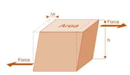
Fig: Shear Deformation of Body
4. Poisson’s Ratio
When a body is subjected to simple tensile stress within its elastic limits then there is a change in the dimensions of the body in the direction of the load as well as in the opposite direction. When these changed dimensions are divided with their original dimensions, longitudinal strain and lateral strain are obtained.
Poisson’s ration ( μ) = Lateral Strain / Longitudinal Strain
The ratio of the lateral strain to the longitudinal strain is called Poisson’s ratio. It is represented by the symbol “µ”. Poisson’s ratio is maximum for an ideal elastic incompressible material and its value is 0.5. For most of the engineering materials, Poisson’s ratio lies between 0.25 and 0.33. It has no units.
Q6) What is their relationship between electric constant?
A6) Relationship between Elastic Constants
E = 2G(1+μ)
E = 3K(1-2μ)
E = 9KG/ (3K + G)
μ=(3K-2G) / (6K + 2G)
Q7) Describe the Stress-strain diagram for ductile
A7) For Ductile Metal –
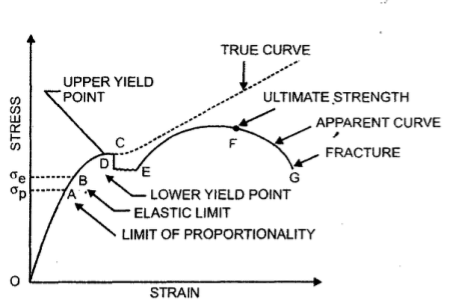
Fig. Stress-Strain Diagram (Ductile Metal)
σT = K(εT)n
Where K is the strength coefficient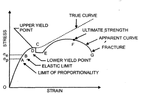
n is the strain hardening exponent
n = 0 perfectly plastic solid
n = 1 elastic solid for most metals, 0.1< n < 0.5
Q8) Describe the Stress-strain diagram for brittle
A8) For Brittle Metal –

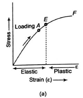
Fig. Stress-Strain Diagram (Brittle Metal)
Q9) Define terms Factor of safety
A9) Factor of safety
FOS = failure stress / working or allowable stress
Q10) Explain the Shear force and bending moment in beams
A10) Shear Force
A shear force that tends to move the left of the section upward or the right side of the section downward will be regarded as positive. Similarly, a shear force that has the tendency to move the left side of the section downward or the right side upward will be considered a negative shear force (see Figure 4.2c and Figure 4.2d).
Bending Moment
A bending moment is considered positive if it tends to cause concavity upward (sagging). If the bending moment tends to cause concavity downward (hogging), it will be considered a negative bending moment (see Figure 4.2e and Figure 4.2f).
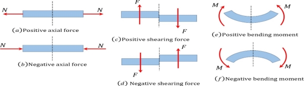
Fig. Sign conventions for axial force, shearing force, and bending moment.


