Unit – 1
Introduction
Q1) Define Computer Architecture.
A1)
(1) It is concerned with the structure and behavior of the computer.
(2) It includes the information formats, the instruction set and techniques for addressing memory.
Q2) Define Computer Organization.
A2)
(1) It describes the function and design of the various units of digital computer that store and process information.
(2) It refers to the operational units and their interconnections that realize the architectural specifications.
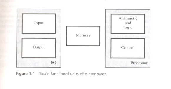
Q3) What are the components of a computer.
A3)
- Input unit
- Memory unit
- Arithmetic and Logic Unit
- Output unit
- Control unit
Q4) Draw the block diagram of computer.
A4)


Q5) What is Execution time/Response time?
A5)
Response time also called execution time. The total time required for the computer to complete a task, including disk accesses, memory accesses, I/O activities, operating system overhead, CPU execution time, and so on.
Q6) What is CPU execution time, user CPU time and system CPU time?
A6)
CPU time: The actual time the CPU spends computing for a specific task.
User CPU time: The CPU time spent in a program itself.
System CPU time: The CPU time spent in the operating system performing tasks on behalf of the program.
Q7) What is clock cycle and clock period?
A7)
Clock cycle: The time for one clock period, usually of the processor clock, which runs at a constant rate.
Clock period: The length of each clock cycle.
Q8) Define CPI
A8)
The term Clock Cycles Per Instruction which is the average number of clocks cycles each instruction takes to execute, is often abbreviated as CPI.
Q9) State and explain the performance equation?
A9)
N denotes number of machine Instructions, suppose that the average number of basic steps needed to execute one machine instruction is S, where each basic step is completed in one clock cycle. If the clock cycle rate is R cycles per second, the processor time is given by
T = (N x S) / R
NOTE: This is often referred to as the basic performance equation.
Q10) Define MIPS.
A10)
MIPS: One alternative to time as the metric is MIPS (Million Instruction Per Second)
MIPS=Instruction count/ (Execution time x1000000). This MIPS measurement is also called Native MIPS to distinguish it from some alternative definitions of MIPS.
Q11) Define MIPS Rate.
A11)
The rate at which the instructions are executed at a given time.
Q12) Define Throughput and Throughput rate.
A12)
(1) Throughput - The total amount of work done in a given time.
(2) Throughput rate- The rate at which the total amount of work done at a given time.
Q13) What are the various types of operations required for instructions?
A13)
(1) Data transfers between the main memory and the CPU registers
(2) Arithmetic and logic operation on data
(3) Program sequencing and control
(4) I/O transfers
Q14) What is a Program?
Q15)
A program is a set of instructions that specify the operations, operands and the sequence by which processing has to occur.
Q16) What is a Computer Instruction?
A15)
A Computer instruction is a binary code that specifies a sequence of micro-operations for the computer.
Q17) What is an Instruction Code?
A16)
An instruction code is a group of bits that instruct the computer to perform a specific operation.
Q18) What is an Operation Code (Opcode)?
A17)
The operation code of an instruction is a group of bits that define operations as add, subtract, multiply, shift and complement etc.
Q19) Define Instruction Format.
A18)
Instructions are represented as numbers. Therefore, entire programs can be stored in memory to be read or written just like numbers (data). Thus, simplifies software/Hardware of computer systems. Each instruction is encoded in binary called machine code.
Q20) What are the Most Common Fields of An Instruction Format?
A19)
--An operation code field that specifies the operation to be performed.
--An address field that designates, a memory address or register.
--A mode field that specifies the way the operand or the effective address is determined
Q21) Explain the address instruction?
A20)
• Three-address instruction-it can be represented as
ADD A, B, C
Operands A, B are called source operand and C is called destination operand.
• Two-address instruction-it can be represented as
ADD A, B
• One address instruction-it can be represented as
LOAD A
ADD B
STORE C
Q22) What is the straight-line sequencing?
A21)
The CPU control circuitry automatically proceed to fetch and execute instruction, one at a time in the order of the increasing addresses. This is called straight line sequencing.
Q23) Write down the MIPS Assembly language notation for arithmetic operations.
A22)
Category | Instruction | Example | Meaning | Comments |
Arithmetic | Add | Add $s1,$s2,$s3 | $s1 = $s2 + $s3 | Three register operands |
Subtract | Sub $s1,$s2,$s3 | $s1 = $s2 – $s3 | Three register operands | |
Add immediate | Addi $s1,$s2,20 | $s1 = $s2 + 20 | Used to add constants |
Q24) Write down the MIPS Assembly language notation for data transfer operations.
A23)
Category | Instruction | Example | Meaning | Comments |
Data transfer | Load word | Lw $s1,20($s2) | $s1 = Memor y[$s2 + 20] | Word from memory to register |
Store word | Sw $s1,20($s2) | Memor y[$s2 + 20] = $s1 | Word from register to memor y | |
Load half | Lh $s1,20($s2) | $s1 = Memor y[$s2 + 20] | Halfword memory to register | |
Load half unsigned | Lhu $s1,20($s2) | $s1 = Memor y[$s2 + 20] | Halfword memory to register | |
Store half | Sh $s1,20($s2) | Memor y[$s2 + 20] = $s1 | Halfword register to memor y | |
Load byte | Lb $s1,20($s2) | $s1 = Memor y[$s2 + 20] | Byte from memory to register | |
Load byte unsigned | Lbu $s1,20($s2) | $s1 = Memor y[$s2 + 20] | Byte from memory to register | |
Store byte | Sb $s1,20($s2) | Memor y[$s2 + 20] = $s1 | Byte from register to memory | |
Load linked word | Ll $s1,20($s2) | $s1 = Memor y[$s2 + 20] | Load word as 1st half of atomic swap | |
Store condition. Word | Sc $s1,20($s2) | Memory[$s2+20]=$s1;$s1=0 or 1 | Store word as 2nd half of atomic swap | |
Load upper immed. | Lui $s1,20 | $s1 = 20 * 216 | Loads constant in upper 16 bits |
Q25) Wrie down the MIPS Assembly language notation for Logical operations.
A24)
Category | Instruction | Example | Meaning | Comments |
Logical | And | And $s1,$s2,$s3 | $s1 = $s2 & $s3 | Three reg. operands; bit-by-bit AND |
Or | Or $s1,$s2,$s3 | $s1 = $s2 | $s3 | Three reg. operands; bit-by-bit OR | |
Nor | Nor $s1,$s2,$s3 | $s1 = ~ ($s2 | $s3) | Three reg. operands; bit-by-bit NOR | |
And immediate | Andi $s1,$s2,20 | $s1 = $s2 & 20 | Bit-by-bit AND reg with constant | |
Or immediate | Ori $s1,$s2,20 | $s1 = $s2 | 20 | Bit-by-bit OR reg with constant | |
Shift left logical | Sll $s1,$s2,10 | $s1 = $s2 << 10 | Shift left by constant | |
Shift right logical | Srl $s1,$s2,10 | $s1 = $s2 >> 10 | Shift right by constant |
Q26) Write down the MIPS Assembly language notation for conditional branch operations.
A25)
Category | Instruction | Example | Meaning | Comments |
Conditional branch | Branch on equal | Beq $s1,$s2,25 | If ($s1 == $s2) go to PC + 4 + 100 | Equal test; PC-relative branch |
Branch on not equal | Bne $s1,$s2,25 | If ($s1!= $s2) go to PC + 4 + 100 | Not equal test; PC-relative | |
Set on less than | Slt $s1,$s2,$s3 | If ($s2 < $s3) $s1 = 1; Else $s1 = 0 | Compare less than; for beq, bne | |
Set on less than unsigned | Sltu $s1,$s2,$s3 | If ($s2 < $s3) $s1 = 1; Else $s1 = 0 | Compare less than unsigned | |
Set less than immediate | Slti $s1,$s2,20 | If ($s2 < 20) $s1 = 1; Else $s1 = 0 | Compare less than constant | |
Set less than immediate unsigned | Sltiu $s1,$s2,20 | If ($s2 < 20) $s1 = 1; Else $s1 = 0 | Compare less than constant unsigned |
Q27) Write down the MIPS Assembly language notation for Unconditional branch operations.
A26)
Category | Instruction | Example | Meaning | Comments |
Unconditional jump | Jump | j 2500 | Go to 10000 | Jump to target address |
Jump register | Jr $ra | Go to $ra | For switch, procedure return | |
Jump and link | Jal 2500 | $ra = PC + 4; go to 10000 | For procedure call |
Q28) What is Addressing Modes?
A27)
The different ways in which the location of an operand is specified in an instruction is called as Addressing mode.
Q29) What are the different types of addressing Modes?
A28)
Immediate mode
Register mode
Absolute mode
Indirect mode
Index mode
Base with index
Base with index and offset
Relative mode
Auto-increment mode
Auto-decrement mode
Q30) Define Register mode and Absolute Mode with examples.
A29)
Register mode
The operand is the contents of the processor register.
The name (address) of the register is given in the instruction.
Absolute Mode (Direct Mode):
- The operand is in new location.
- The address of this location is given explicitly in the instruction.
E.g.: MOVE LOC, R2
The above instruction uses the register and absolute mode.
The processor register is the temporary storage where the data in the register are accessed using register mode.
The absolute mode can represent global variables in the program.
Mode Assembler Syntax Addressing Function
Register mode | Ri | EA=Ri |
Absolute mode | LOC | EA=LOC |
Where EA-Effective Address
Q31) What is an Immediate addressing Mode?
A30)
The operand is given explicitly in the instruction.
E.g.: Move 200 immediate, R0
It places the value 200 in the register R0. The immediate mode used to specify the value of source operand.
In assembly language, the immediate subscript is not appropriate so # symbol is used. It can be re-written as
Move #200, R0
Assembly Syntax: Addressing Function
Immediate #value Operand =value
Q32) Define Indirect addressing Mode.
A31)
- The effective address of the operand is the contents of a register.
- We denote the indirection by the name of the register or new address given in the instruction.
Example of Indirect Mode
Address of an operand (B) is stored into R1 register. If we want this operand, we can get it through register R1(indirection).
The register or new location that contains the address of an operand is called the pointer.
Mode Assembler Syntax Addressing Function
Indirect Ri, LOC EA=[Ri] or EA=[LOC]
Q33) Define Index addressing Mode.
A32)
The effective address of an operand is generated by adding a constant value to the contents of a register.
 The constant value uses either special purpose or general purpose Register
We indicate the index mode symbolically as,
X(Ri)
Where X – denotes the constant value contained in the instruction
Ri – It is the name of the register involved.
The Effective Address of the operand is,
EA=X + [Ri]
The index register R1 contains the address of a new location and the value of X defines an offset (also called a displacement).
To find operand,
- First go to Reg R1 (using address)-read the content from R1-1000
- Add the content 1000 with offset 20 get the result.
- 1000+20=1020
- Here the constant X refers to the new address and the contents of index register define the offset to the operand.
- The sum of two values is given explicitly in the instruction and the other is stored in register.
E.g.: Add 20(R1), R2 (or) EA=>1000+20=1020
Index Mode | Assembler Syntax | Addressing Function |
Index | X(Ri) | EA=[Ri]+X |
Base with Index | (Ri,Rj) | EA=[Ri]+[Rj] |
Base with Index and offset | X(Ri,Rj) | EA=[Ri]+[Rj] +X |
Q34) What is a Relative Addressing mode?
A33)
It is same as index mode. The difference is, instead of general-purpose register, here we can use program counter (PC).
Relative Mode:
 The Effective Address is determined by the Index mode using the PC in place of the general purpose register.
 This mode can be used to access the data operand. But its most common use is to specify the target address in branch instruction. E.g., Branch>0 Loop
 It causes the program execution to go to the branch target location. It is identified by the name loop if the branch condition is satisfied.
Mode Assembler Syntax Addressing Function
Relative X(PC) EA=[PC]+X
Q35) Define Auto-increment addressing mode.
A34)
- The Effective Address of the operand is the contents of a register in the instruction.
- After accessing the operand, the contents of this register is automatically incremented to point to the next item in the list.
Mode Assembler syntax Addressing Function
Auto-increment (Ri)+ EA=[Ri]; Increment Ri
Q36) Define Auto-decrement addressing mode.
A35)
- The Effective Address of the operand is the contents of a register in the instruction.
- After accessing the operand, the contents of this register is automatically decremented to point to the next item in the list.
Mode Assembler Syntax Addressing Function
Auto-decrement -(Ri) EA=[Ri]; Decrement Ri
Q37) Define BUS and its ARCHITECTURE?
A36)
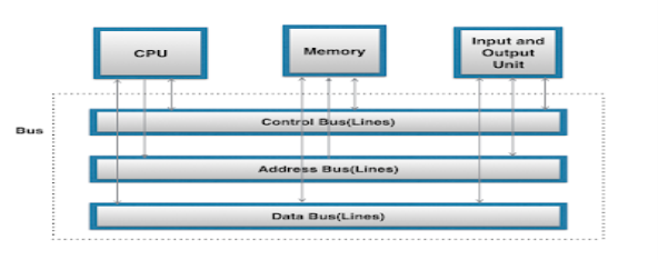
A bus is a communication system in computer architecture that transfers data between components inside a computer, or between computers.
The term encompasses all the components related to hardware (wire, optical fibre, etc.) and software, including communication protocol.
The following are a few points to describe a computer bus:
- A bus is a group of lines/wires which carry computer signals.
- A bus is the means of shared transmission.
- Lines are assigned for providing descriptive names. — carries a single electrical signal, e.g. 1-bit memory address, data bits series, or timing control that turns the device on or off.
- Data can be transferred from one computer system location to another (between different I / O modules, memory, and CPU).
- The bus is not only cable but also hardware (bus architecture), protocol, program, and bus controller.
Bus is a group of wires that connects different components of the computer. It is used for transmitting data, control signal and memory address from one component to another. A bus can be 8 bit, 16 bit, 32 bit and 64 bit. A 32-bit bus can transmit 32-bit information at a time.

Fig 1-Bus Architecture
Data Bus:
Data Lines provide a path for moving data between system modules. It is bidirectional which means data lines are used to transfer data in both directions. For example, CPU can read data on these lines as well as send data out of these lines to a memory location or to a port.
Address bus:
Address Lines are collectively called as address bus. In any bus, the no. Of lines in address are usually 16, 20, 24, or more depending on type and architecture of bus. On these lines, CPU sends out the address of memory location on I/O Port that is to be written on or read from.
In short, it is an internal channel from CPU to Memory across which the address of data is transmitted. Here the communication is one way that is, the address is send from CPU to Memory and I/O Port but not Memory and I/O port send address to CPU on that line and hence these lines are unidirectional.
Control Bus:
Control Lines are collectively called as Control Bus. Control Lines are gateway used to transmit and receives control signals between the microprocessor and various devices attached to it. In other words, Control Lines are used by CPUs for Communicating with other devices within the computer.
Control Lines signals are:
Memory Read.
Memory Write.
I/O Read.
I/O Write.
Bus Request.
Bus Grant, etc.
Q38) Define bus arbitration?
A37)
There are mainly three types of Buses Data, Control and Address Bus as explained in above topic.
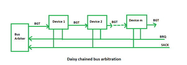
Bus Arbitration refers to the process by which the current bus master accesses and then leaves the control of the bus and passes it to the another bus requesting processor unit. The controller that has access to a bus at an instance is known as Bus master.
There are two approaches to bus arbitration:
- Centralized bus arbitration – A single bus arbiter performs the required arbitration.
- Distributed bus arbitration – All devices participate in the selection of the next bus master.
Methods of BUS Arbitration–
There are three bus arbitration methods:
(i)Daisy Chaining method–
It is a centralized bus arbitration method. During any bus cycle, the bus master may be any device – the processor or any DMA controller unit, connected to the bus.

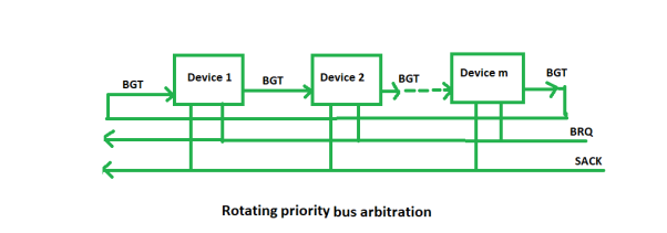
(ii) Polling or Rotating Priority method –
In this method, the devices are assigned unique priorities and complete to access the bus, but the priorities are dynamically changed to give every device an opportunity to access the bus.

(iii) Fixed priority or Independent Request method –
In this method, the bus control passes from one device to another only through the centralized bus arbiter.
