Unit - 3
Control Unit
Q1) Define pipelining.
A1)
Pipelining is a technique of decomposing a sequential process into sub operations with each sub process being executed in a special dedicated segment that operates concurrently with all other segments.
Q2) Define parallel processing.
A2)
Parallel processing is a term used to denote a large class of techniques that are used to provide simultaneous data-processing tasks for the purpose of increasing the computational speed of a computer system. Instead of processing each instruction sequentially as in a conventional computer, a parallel processing system is able to perform concurrent data
Processing to achieve faster execution time.
Q3) Define instruction pipeline.
A3)
The transfer of instructions through various stages of the CPU instruction cycle., including fetch opcode, decode opcode, compute operand addresses. Fetch operands, execute Instructions and store results. This amounts to realizing most (or) all of the CPU in the form of multifunction pipeline called an instruction pipelining.
Q4) What are the steps required for a pipelined processor to process the instruction?
A4)
• F Fetch: read the instruction from the memory
• D Decode: decode the instruction and fetch the source operand(s).
• E Execute: perform the operation specified by the instruction.
• W Write: store the result in the destination location
Q5) What are Hazards?
A5)
A hazard is also called as hurdle. The situation that prevents the next instruction in the instruction stream from executing during its designated Clock cycle. Stall is introduced by hazard. (Ideal stage)
Q6) State different types of hazards that can occur in pipeline.
A6)
The types of hazards that can occur in the pipelining were,
1. Data hazards.
2. Instruction hazards.
3. Structural hazards.
Q7) Define Data hazards
A7)
A data hazard is any condition in which either the source or the destination operands of an instruction are not available at the time expected in pipeline. As a result, some operation has to be delayed, and the pipeline stalls.
Q8) Define Instruction hazards
A8)
The pipeline may be stalled because of a delay in the availability of an instruction.
For example, this may be a result of miss in cache, requiring the instruction to be fetched from the main memory. Such hazards are called as Instruction hazards or Control hazards.
Q9) Define Structural hazards?
A9)
The structural hazards are the situation when two instructions require the use of a given hardware resource at the same time.
The most common case in which this hazard may arise is access to memory.
Q10) What are the classification of data hazards?
A10)
Classification of data hazard: A pair of instructions can produce data hazard by referring reading or writing the same memory location. Assume that i is executed before J. So, the hazards can be classified as,
1. RAW hazard
2. WAW hazard
3. WAR hazard
Q11) Define RAW hazard: (read after write)
A11)
Instruction ‘j’ tries to read a source operand before instruction ‘i’ writes it.
Q12) Define WAW hazard :( write after write)
A12)
Instruction ‘j’ tries to write a source operand before instruction ‘i’ writes it.
Q13) Define WAR hazard :( write after read)
A13)
Instruction ‘j’ tries to write a source operand before instruction ‘i’ reads it.
Q14) How data hazard can be prevented in pipelining?
A14)
Data hazards in the instruction pipelining can prevented by the following techniques.
a) Operand Forwarding
b) Software Approach
Q15) How Compiler is used in Pipelining?
A15)
A compiler translates a high-level language program into a sequence of machine instructions. To reduce N, we need to have suitable machine instruction set and a compiler that makes good use of it. An optimizing compiler takes advantages of various features of the target processor to reduce the product N*S, which is the total number of clock cycles needed to execute a program. The number of cycles is dependent not only on the choice of instruction, but also on the order in which they appear in the program. The compiler may rearrange program instruction to achieve better performance of course, such changes must not affect of the result of the computation.
Q16) How addressing modes affect the instruction pipelining?
A16)
Degradation of performance is an instruction pipeline may be due to address dependency where operand address cannot be calculated without available information needed by addressing mode for e.g. An instruction with register indirect mode cannot proceed to fetch the operand if the previous instructions is loading the address into the register. Hence operand access is delayed degrading the performance of pipeline.
Q17) What is locality of reference?
A17)
Many instructions in localized area of the program are executed repeatedly during some time period and the remainder of the program is accessed relatively infrequently. This is referred as locality of reference.
Q18) What is the need for reduced instruction chip?
A18)
• Relatively few instruction types and addressing modes.
• Fixed and easily decoded instruction formats.
• Fast single-cycle instruction execution.
• Hardwired rather than micro programmed control
Q19) Define memory access time?
A19)
The time that elapses between the initiation of an operation and completion of that operation, for example, the time between the READ and the MFC signals. This is Referred to as memory access time.
Q20) Define memory cycle time.
A20)
The minimum time delay required between the initiations of two successive memory operations, for example, the time between two successive READ operations.
Q21) Define Static Memories.
A21)
Memories that consist of circuits capable of retaining the state as long as power is applied are known as static memories.
Q22) List out Various branching technique used in micro program control unit?
A22)
a) Bit-Oring
b) Using Conditional Variable
c) Wide Branch Addressing
Q23) How the interrupt is handled during exception?
A23)
* CPU identifies source of interrupt
* CPU obtains memory address of interrupt handles
* Pc and other CPU status information are saved
* Pc is loaded with address of interrupt handler and handling program to handle it.
Q24) List out the methods used to improve system performance.
A24)
The methods used to improve system performance are
1. Processor clock
2.Basic Performance Equation
3.Pipelining
4.Clock rate
5.Instruction set
6.Compiler
Q25) Explain the Instruction Cycle in detail?
A25)
The Instruction Cycle –
Each phase of Instruction Cycle can be decomposed into a sequence of elementary micro-operations. In the above examples, there is one sequence each for the Fetch, Indirect, Execute and Interrupt Cycles.
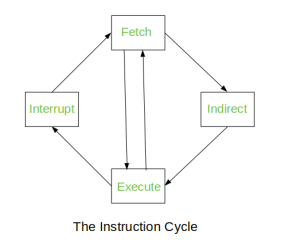
Fig– Instruction Cycle
The Indirect Cycle is always followed by the Execute Cycle. The Interrupt Cycle is always followed by the Fetch Cycle. For both fetch and execute cycles, the next cycle depends on the state of the system.
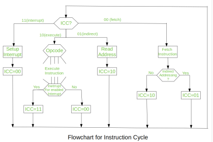
Fig – Flowchart of instruction cycle
We assumed a new 2-bit register called Instruction Cycle Code (ICC). The ICC designates the state of processor in terms of which portion of the cycle it is in:
00: Fetch Cycle |
At the end of each cycle, the ICC is set appropriately. The above flowchart of Instruction Cycle describes the complete sequence of micro-operations, depending only on the instruction sequence and the interrupt pattern (this is a simplified example). The operation of the processor is described as the performance of a sequence of micro-operation.
Different Instruction Cycles:
The Fetch Cycle –
At the beginning of the fetch cycle, the address of the next instruction to be executed is in the Program Counter (PC).
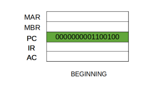
Step 1: The address in the program counter is moved to the memory address register (MAR), as this is the only register which is connected to address lines of the system bus.
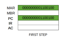
Step 2: The address in MAR is placed on the address bus, now the control unit issues a READ command on the control bus, and the result appears on the data bus and is then copied into the memory buffer register (MBR). Program counter is incremented by one, to get ready for the next instruction. (These two actions can be performed simultaneously to save time)
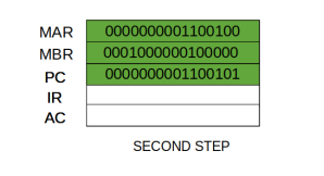
Step 3: The content of the MBR is moved to the instruction register (IR).
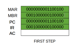
Thus, a simple Fetch Cycle consists of three steps and four micro-operations. Symbolically, we can write these sequence of events as follows:
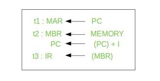
Here ‘I’ is the instruction length. The notations (t1, t2, t3) represents successive time units. We assume that a clock is available for timing purposes and it emits regularly spaced clock pulses. Each clock pulse defines a time unit. Thus, all time units are of equal duration. Each micro-operation can be performed within the time of a single time unit. First time unit: Move the contents of the PC to MAR.
Second time unit: Move contents of memory location specified by MAR to MBR. Increment content of PC by I. Third time unit: Move contents of MBR to IR.
Note: Second and third micro-operations both take place during the second time unit.
The Indirect Cycles –
Once an instruction is fetched, the next step is to fetch source operands. Source Operand is being fetched by indirect addressing (it can be fetched by any addressing mode, here it’s done by indirect addressing). Register-based operands need not be fetched. Once the opcode is executed, a similar process may be needed to store the result in main memory. Following micro-operations takes place:
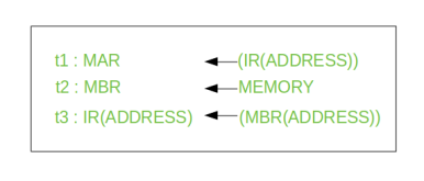
Step 1: The address field of the instruction is transferred to the MAR. This is used to fetch the address of the operand.
Step 2: The address field of the IR is updated from the MBR. (So that it now contains a direct addressing rather than indirect addressing)
Step 3: The IR is now in the state, as if indirect addressing has not been occurred.
Note: Now IR is ready for the execute cycle, but it skips that cycle for a moment to consider the Interrupt Cycle.
The Execute Cycle
The other three cycles (Fetch, Indirect and Interrupt) are simple and predictable. Each of them requires simple, small and fixed sequence of micro-operation. In each case same micro-operation are repeated each time around.
Execute Cycle is different from them. Like, for a machine with N different opcodes there are N different sequence of micro-operations that can occur.
Let’s take a hypothetical example: consider an add instruction:

Here, this instruction adds the content of location X to register R. Corresponding micro-operation will be:
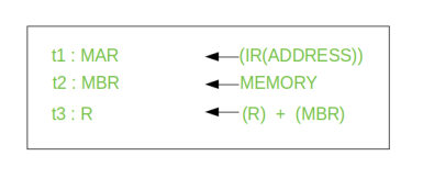
We begin with the IR containing the ADD instruction.
Step 1: The address portion of IR is loaded into the MAR.
Step 2: The address field of the IR is updated from the MBR, so the reference memory location is read.
Step 3: Now, the contents of R and MBR are added by the ALU.
Let’s take a complex example:

Here, the content of location X is incremented by 1. If the result is 0, the next instruction will be skipped. Corresponding sequence of micro-operation will be:
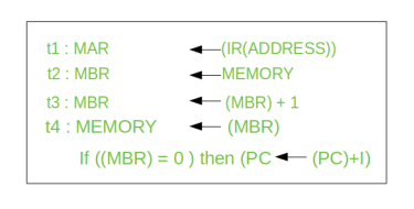
Here, the PC is incremented if (MBR) = 0. This test (is MBR equal to zero or not) and action (PC is incremented by 1) can be implemented as one micro-operation.
Note: This test and action micro-operation can be performed during the same time unit during which the updated value MBR is stored back to memory.
The Interrupt Cycle:
At the completion of the Execute Cycle, a test is made to determine whether any enabled interrupt has occurred or not. If an enabled interrupt has occurred then Interrupt Cycle occurs. The nature of this cycle varies greatly from one machine to another.
Let’s take a sequence of micro-operation:
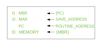
Step 1: Contents of the PC is transferred to the MBR, so that they can be saved for return.
Step 2: MAR is loaded with the address at which the contents of the PC are to be saved.
PC is loaded with the address of the start of the interrupt-processing routine.
Step 3: MBR, containing the old value of PC, is stored in memory.
Q26) Define Hardwire and micro programmed control?
A26)
Hardwired Control
The Hardwired Control organization involves the control logic to be implemented with gates, flip-flops, decoders, and other digital circuits.
The following image shows the block diagram of a Hardwired Control organization.
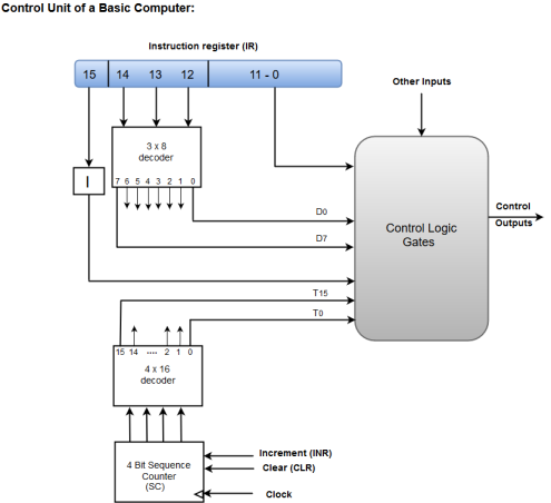
Figure – Control unit of a basic computer
- A Hard-wired Control consists of two decoders, a sequence counter, and a number of logic gates.
- An instruction fetched from the memory unit is placed in the instruction register (IR).
- The component of an instruction register includes; I bit, the operation code, and bits 0 through 11.
- The operation code in bits 12 through 14 are coded with a 3 x 8 decoder.
- The outputs of the decoder are designated by the symbols D0 through D7.
- The operation code at bit 15 is transferred to a flip-flop designated by the symbol I.
- The operation codes from Bits 0 through 11 are applied to the control logic gates.
- The Sequence counter (SC) can count in binary from 0 through 15.
Micro-programmed Control
The Microprogrammed Control organization is implemented by using the programming approach.
In Microprogrammed Control, the micro-operations are performed by executing a program consisting of micro-instructions.
The following image shows the block diagram of a Microprogrammed Control organization.

Figure- Microprogrammed control unit of a basic computer
- The Control memory address register specifies the address of the micro-instruction.
- The Control memory is assumed to be a ROM, within which all control information is permanently stored.
- The control register holds the microinstruction fetched from the memory.
- The micro-instruction contains a control word that specifies one or more micro-operations for the data processor.
- While the micro-operations are being executed, the next address is computed in the next address generator circuit and then transferred into the control address register to read the next microinstruction.
- The next address generator is often referred to as a micro-program sequencer, as it determines the address sequence that is read from control memory.
Q27) Define horizontal and vertical microprogramming?
A27)
A language is used to deign micro programmed control unit known as a microprogramming language. Each line describes a set of micro-operations occurring at one time and is known as a microinstruction. A sequence of instructions is known as a micro program, or firmware.
For each micro-operation, control unit has to do is generate a set of control signals. Thus, for any micro-operation, control line emanating from the control unit is either on or off. This condition can, be represented by a binary digit for each control line. So, we could construct a control word in which each bit represents one control line. Now add an address field to each control word, indicating the location of the next control word to be executed if a certain condition is true.
The result is known as a horizontal microinstruction, which is shown in Figure below. The format of the microinstruction or control word is as follows. There is one bit for each internal processor control line and one bit for each system bus control line.
There is a condition field indicating the condition under which there should be a branch, and there is a field with the address of the microinstruction to be executed next when a branch is taken.
Such a microinstruction is interpreted as follows:
1 - To execute this microinstruction, turn on all the control lines indicated by a 1 bit leave off all control lines indicated by a 0 bit.
The resulting control signals will cause one or more micro-operations to be performed.
2 If the condition indicated by the condition bits is false, execute the next microinstruction in sequence.
3 If the condition indicated by the condition bits is true, the next microinstruction to be executed is indicated in the address field
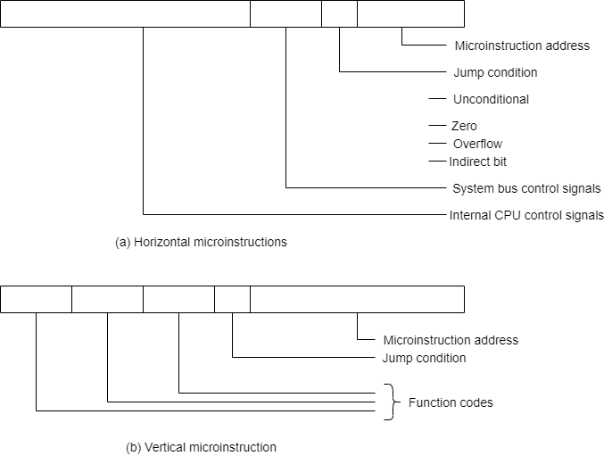
Fig- Typical Micro Instruction Format
In a vertical microinstruction, a code is used for each action to be performed, and the decoder translates this code into individual control signals. The advantage of vertical microinstructions is that they are more compact (fewer bits) than horizontal microinstructions.
In Figure below shows how these control words or microinstructions could be arranged in a control memory. The microinstructions in each routine are to be executed sequentially. Each routine ends with a branch or jump instruction indicating where to go next.
There is a special execute cycle routine whose only purpose is to signify that one of the machine instruction routines (AND, ADD, and so on) is to be executed next, depending on the current opcode.
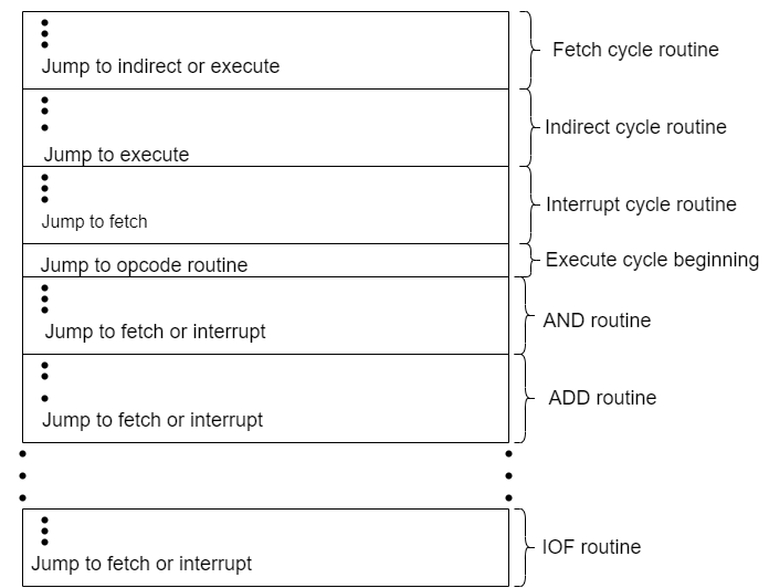
Fig- Organization of Control Memory