Unit - 5
Input / Output
Q1) What are the multimedia applications which use caches?
A1)
Some Multimedia application areas where cache is extensively used are
*Multimedia Entertainment
*Education
*Office Systems
*Audio and video Mail
Q2) Explain virtual memory technique.
A2)
Techniques that automatically move program and data blocks into the physical memory when they are required for execution are called virtual memory technique
Q3) What are virtual and logical addresses?
A3)
The binary addresses that the processor issues for either instruction or data are called virtual or logical addresses.
Q4) Define translation buffer.
A4)
Most commercial virtual memory systems incorporate a mechanism that can avoid the bulk of the main memory access called for by the virtual to physical addresses translation buffer. This may be done with a cache memory called a translation buffer.
Q5) What is branch delay slot?
A5)
The location containing an instruction that may be fetched and then discarded because of the branch is called branch delay slot.
Q6) What is optical memory?
A6)
Optical or light-based techniques for data storage, such memories usually employ optical disk which resemble magnetic disk in that they store binary information in concentric tracks on an electromechanically rotated disk. The information is read as or written optically, however with a laser replacing the read write arm of a magnetic disk drive. Optical memory offers high storage capacities but their access rate is are generally less than those of magnetic disk.
Q7) What are static and dynamic memories?
A7)
Static memory are memories which require periodic no refreshing. Dynamic memories are memories, which require periodic refreshing.
Q8) What are the components of memory management unit?
A8)
A facility for dynamic storage relocation that maps logical memory references into
Physical memory addresses. A provision for sharing common programs stored in memory by different users.
Q9) What is the role of MAR and MDR?
A9)
The MAR (memory address register) is used to hold the address of the location to or from which data are to be transferred and the MDR (memory data register) contains the data to be written into or read out of the addressed location.
Q10) Distinguish Between Static RAM and Dynamic RAM?
A10)
Static RAM are fast, but they come at high cost because their cells require several transistors. Less expensive RAM can be implemented if simpler cells are used. However, such cells do not retain their state indefinitely. Hence, they are called Dynamic RAM.
Q11) Distinguish between asynchronies DRAM and synchronous RAM.
A11)
The specialized memory controller circuit provides the necessary control signals, RAS
And CAS, that govern the timing. The processor must take into account the delay in the response of the memory. Such memories are referred to as asynchronous DRAMS. The DRAM whose operations are directly synchronized with a clock signal. Such Memories are known as synchronous DRAM.
Q12) What do you mean associative mapping technique?
A12)
The tag of an address received from the CPU is compared to the tag bits of each block of the cache to see if the desired block is present. This is called associative mapping technique.
Q13) What is SCSI?
A13)
Small computer system interface can be used for all kinds of devices including RAID
Storage subsystems and optical disks for large- volume storage applications.
Q14) What are the two types of latencies associated with storage?
A14)
The latency associated with storage is divided into 2 categories
1. Seek Latencies which can be classified into Overlapped seek, Mid transfer seek and Elevator seek
2. Rotational Latencies which can be reduced either by Zero latency read or Write and Interleave factor.
Q15) What do you mean by Disk Spanning?
A15)
Disk spanning is a method of attaching drives to a single host adapter. All drives appear as a single contiguous logical unit. Data is written to the first drive first and when the drive is full, the controller switches to the second drive, then the second drive writes until its full.
Q16) Define the term RELIABILITY
A16)
“Means feature that help to avoid and detect such faults. A reliable system does not silently continue and delivery result that include interacted and corrupted data, instead it corrects the corruption when possible or else stops
Q17) Define the term AVAILABLITY.
A17)
“Means features that follow the system to stay operational even often faults do occur. A highly available system could disable do the main functioning portion and continue operating at the reduced capacity”
Q18) How the interrupt is handled during exception?
A18)
* CPU identifies source of interrupt
* CPU obtains memory address of interrupt handles
* Pc and other CPU status information are saved
* Pc is loaded with address of interrupt handler and handling program to handle it
Q19) What is IO mapped input output?
A19)
A memory reference instruction activated the READ M (or)WRITE M control line and does not affect the IO device. Separate IO instruction is required to activate the READ IO and WRITE IO lines, which cause a word to be transferred between the address aio port and the CPU. The memory and IO address space are kept separate.
Q20) Specify the three types of the DMA transfer techniques?
A20)
--Single transfer mode (cycle stealing mode)
--Block Transfer Mode (Brust Mode)
--Demand Transfer Mode
--Cascade Mode
Q21) What is an interrupt?
A21)
An interrupt is an event that causes the execution of one program to be suspended and another program to be executed.
Q22) What are the uses of interrupts?
A22)
*Recovery from errors
*Debugging
*Communication between programs
*Use of interrupts in operating system
Q23) Define vectored interrupts.
Q24)
In order to reduce the overhead involved in the polling process, a device requesting an interrupt may identify itself directly to the CPU. Then, the CPU can immediately start executing the corresponding interrupt-service routine. The term vectored interrupts refer to all interrupt handling schemes base on this approach.
Q25) Name any three of the standard I/O interface.
Q26)
*SCSI (small computer system interface), bus standards
*Back plane bus standards
*IEEE 796 bus (multibus signals)
*NUBUS & IEEE 488 bus standard
Q27) What is an I/O channel?
A25)
An i/o channel is actually a special purpose processor, also called peripheral processor. The main processor initiates a transfer by passing the required information in the input output channel. The channel then takes over and controls the actual transfer of data.
Q28) Why program controlled I/O is unsuitable for high-speed data transfer?
A26)
In program controlled i/o considerable overhead is incurred because several program instructions have to be executed for each data word transferred between the external devices and MM. Many high-speed peripheral; devices have a synchronous mode of operation that is data transfer are controlled by a clock of fixed frequency, independent of the CPU.
Q29) What is NUBUS?
A27)
A NUBUS is a processor independent, synchronous bus standard intended for use in 32-bit micro processor system. It defines a backplane into which up to 16 devices may be plugged each in the form of circuit board of standard dimensions.
Q30) Name some of the IO devices.
A28)
*Video terminals
*Video displays
*Alphanumeric displays
*Graphics displays
* Flat panel displays
*Printers
*Plotters
Q31) What are the steps taken when an interrupt occurs?
A29)
*Source of the interrupt
*The memory address of the required ISP
* The program counter &CPU information saved in subroutine
*Transfer control back to the interrupted program
Q32) Differences between peripheral devices and CPU?
A30)
- Peripherals are electromechnical and electromagnetic devices and CPU and memory are electronic devices. Therefore, a conversion of signal values may be needed.
2. The data transfer rate of peripherals is usually slower than the transfer rate of CPU and consequently, a synchronization mechanism may be needed.
3. Data codes and formats in the peripherals differ from the word format in the CPU and memory.
4. The operating modes of peripherals are different from each other and must be controlled so as not to disturb the operation of other peripherals connected to the CPU.
To resolve these differences, computer systems include special hardware components between the CPU and Peripherals to supervises and synchronizes all input and out transfers. These components are called Interface Units because they interface between the processor bus and the peripheral devices.
Q33) Explain ports and its types?
A31)
A connection point that acts as interface between the computer and external devices like mouse, printer, modem, etc. is called port.
Ports are of two types:
- Internal port: It connects the motherboard to internal devices like hard disk drive, CD drive, internal modem, etc.
- External port: It connects the motherboard to external devices like modem, mouse, printer, flash drives, etc.
Some of the most commonly used ports are shown below:
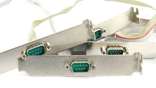
Serial Port
Serial ports transmit data sequentially one bit at a time. So, they need only one wire to transmit 8 bits. However, it also makes them slower. Serial ports are usually 9-pin or 25-pin male connectors. They are also known as COM (communication) ports or RS323C ports.
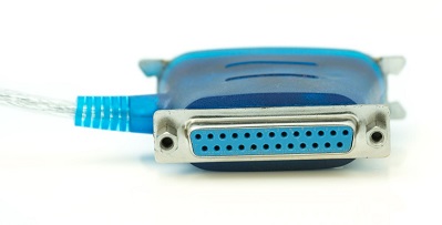
Parallel Port
Parallel ports can send or receive 8 bits or 1 byte at a time. Parallel ports come in form of 25-pin female pins and are used to connect printer, scanner, external hard disk drive, etc.
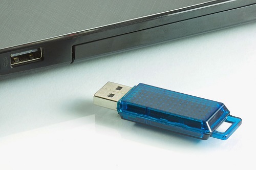
USB Port
USB stands for Universal Serial Bus. It is the industry standard for short distance digital data connection. USB port is a standardized port to connect a variety of devices like printer, camera, keyboard, speaker, etc.
PS-2 Port
PS/2 stands for Personal System/2. It is a female 6-pin port standard that connects to the male mini-DIN cable. PS/2 was introduced by IBM to connect mouse and keyboard to personal computers. This port is now mostly obsolete, though some systems compatible with IBM may have this port.
Infrared Port
Infrared port is a port that enables wireless exchange of data within a radius of 10m. Two devices that have infrared ports are placed facing each other so that beams of infrared lights can be used to share data.
Q34) Explain Interrupts in detail?
A32)
Interrupt is a signal emitted by hardware or software when a process or an event needs immediate attention. It alerts the processor to a high priority process requiring interruption of the current working process. In I/O devices one of the bus control lines is dedicated for this purpose and is called the Interrupt Service Routine (ISR).
When a device raises an interrupt at let’s say process i, the processor first completes the execution of instruction i. Then it loads the Program Counter (PC) with the address of the first instruction of the ISR. Before loading the Program Counter with the address, the address of the interrupted instruction is moved to a temporary location. Therefore, after handling the interrupt the processor can continue with process i+1.
While the processor is handling the interrupts, it must inform the device that its request has been recognized so that it stops sending the interrupt request signal. Also, saving the registers so that the interrupted process can be restored in the future, increases the delay between the time an interrupt is received and the start of the execution of the ISR. This is called Interrupt Latency.
Hardware Interrupts:
In a hardware interrupt, all the devices are connected to the Interrupt Request Line. A single request line is used for all the n devices. To request an interrupt, a device closes its associated switch. When a device requests an interrupt, the value of INTR is the logical OR of the requests from individual devices.
Sequence of events involved in handling an IRQ:
- Devices raise an IRQ.
- Processor interrupts the program currently being executed.
- Device is informed that its request has been recognized and the device deactivates the request signal.
- The requested action is performed.
- Interrupt is enabled and the interrupted program is resumed.
Handling Multiple Devices:
When more than one device raises an interrupt request signal, then additional information is needed to decide which device to be considered first. The following methods are used to decide which device to select: Polling, Vectored Interrupts, and Interrupt Nesting. These are explained as following below.
- Polling:
In polling, the first device encountered with IRQ bit set is the device that is to be serviced first. Appropriate ISR is called to service the same. It is easy to implement but a lot of time is wasted by interrogating the IRQ bit of all devices.
2. Vectored Interrupts:
In vectored interrupts, a device requesting an interrupt identifies itself directly by sending a special code to the processor over the bus. This enables the processor to identify the device that generated the interrupt. The special code can be the starting address of the ISR or where the ISR is located in memory, and is called the interrupt vector.
3. Interrupt Nesting:
In this method, I/O device is organized in a priority structure. Therefore, interrupt request from a higher priority device is recognized where as request from a lower priority device is not. To implement this each process/device (even the processor). Processor accepts interrupts only from devices/processes having priority more than it.
Processor’s priority is encoded in a few bits of PS (Process Status register). It can be changed by program instructions that write into the PS. Processor is in supervised mode only while executing OS routines. It switches to user mode before executing application programs.
Q35) Define I/O interface?
A33)
Input-Output Interface
1. Data Bus Buffer
2. Read/Write Control Logic
3. Port A, Port B register
4. Control and Status register
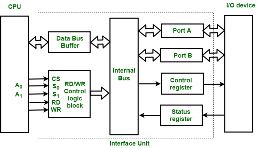
Figure – Interface Unit
These are explained as following below.
Data Bus Buffer:
The bus buffer uses bi-directional data bus to communicate with CPU. All control word data and status information between interface unit and CPU are transferred through data bus.
Port A and Port B:
Port A and Port B are used to transfer data between Input-Output device and Interface Unit. Each port consists of bi-directional data input buffer and bi-directional data output buffer. Interface unit connect directly with an input device and output disk or with device that require both input and output through Port A and Port B i.e., modem, external hard-drive, magnetic disk.
Control and Status Register:
CPU gives control information to control register on basis of control information. Interface unit control input and output operation between CPU and input-output device. Bits which are present in status register are used for checking of status conditions. Status register indicate status of data register, port A, port B and also record error that may be occur during transfer of data.
Read/Write Control Logic:
This block generates necessary control signals for overall device operations. All commands from CPU are accepted through this block. It also allows status of interface unit to be transferred onto data bus through this block accept CS, read and write control signal from system bus and S0, S1 from system address bus. Read and Write signal are used to define direction of data transfer over data bus.
Read Operation: CPU <---- I/O device
Write Operation: CPU ----> I/O device
The read signal direct data transfer from interface unit to CPU and write signal direct data transfer from CPU to interface unit through data bus.
Address bus is used to select to interface unit. Two least significant lines of address bus (A0, A1) are connected to select lines S0, S1. This two select input lines are used to select any one of four registers in interface unit. The selection of interface unit is according to the following criteria:
Read state:
Chip Select | Operation | Select lines | Selection of
Interface unit | ||
CS | Read | Write | S | S | |
0 | 0 | 1 | 0 | 0 | Port A |
0 | 0 | 1 | 0 | 1 | Port B |
0 | 0 | 1 | 1 | 0 | Control Register |
0 | 0 | 1 | 1 | 1 | Status Register |
Write State:
Chip Select | Operation | Select lines | Selection of | ||
CS | Read | Write | S | S | |
0 | 1 | 0 | 0 | 0 | Port A |
0 | 1 | 0 | 0 | 1 | Port B |
0 | 1 | 0 | 1 | 0 | Control Register |
0 | 1 | 0 | 1 | 1 | Status Register |
Example:
If S0, S1 = 0 1, then Port B data register is selected for data transfer between CPU and I/O device.
If S0, S1 = 1 0, then Control register is selected and store the control information send by the CPU.
Q36) Explain Relation between I/O channels and processors?
A34)
The I/O channel represents an extension of DMA concept. An I/O channel has ability to execute I/O instructions that gives complete control over I/O operation. With such devices the CPU doesn't execute I/O instructions. These kinds of instructions are stored in main memory to be executed by a special-purpose processor in I/O channel itself. So, CPU initiates an I/O transfer by instructing I/O channel to execute a program in memory.
Two kinds of I/O channels are commonly used that can be seen in Figure (a and b).
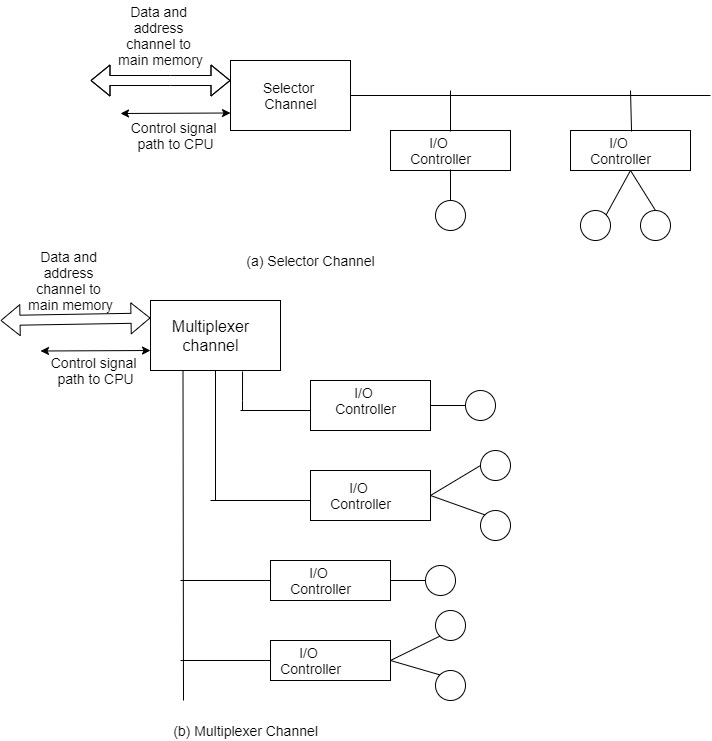
A selector channel controls multiple high-speed devices and at any one time is dedicated to transfer of data with one of those devices. Every device is handled by a controller or I/O interface. So, I/O channel serves in place of CPU in controlling these I/O controllers.
A multiplexer channel can handle I/O with many devices at the same time. If devices are slow then byte multiplexer is used. Let's explain this with illustration. If we have 3 slow devices that need to send individual bytes as:
X1 X2 X3 X4 X5 ......
Y1 Y2 Y3 Y4 Y5......
Z1 Z2 Z3 Z4 Z5......
Then on a byte multiplexer channel they can transmit bytes as X1 Y1 Z1 X2 Y2 Z2 X3 Y3 Z3...... For high-speed devices blocks of data from various devices are interleaved. These devices are known as block multiplexer.
Input-output processor:
The DMA mode of data transfer reduces CPU’s overhead in handling I/O operations. It also allows parallelism in CPU and I/O operations. Such parallelism is necessary to avoid wastage of valuable CPU time while handling I/O devices whose speeds are much slower as compared to CPU. The concept of DMA operation can be extended to relieve the CPU further from getting involved with the execution of I/O operations. This gives rises to the development of special purpose processor called Input-Output Processor (IOP) or IO channel. The Input Output Processor (IOP) is just like a CPU that handles the details of I/O operations. It is more equipped with facilities than those are available in typical DMA controller. The IOP can fetch and execute its own instructions that are specifically designed to characterize I/O transfers. In addition to the I/O – related tasks, it can perform other processing tasks like arithmetic, logic, branching and code translation. The main memory unit takes the pivotal role. It communicates with processor by the means of DMA.
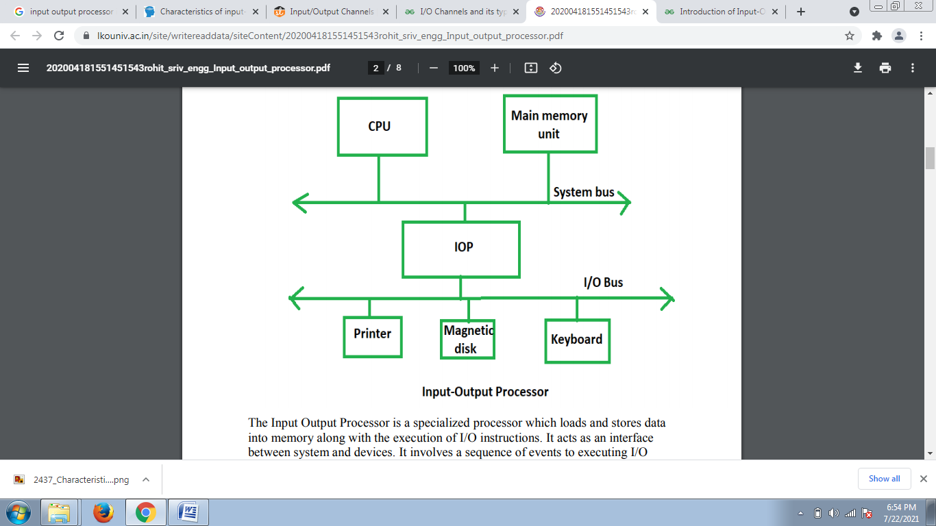
The Input Output Processor is a specialized processor which loads and stores data into memory along with the execution of I/O instructions. It acts as an interface between system and devices. It involves a sequence of events to executing I/O operations and then store the results into the memory.
Advantages:
The I/O devices can directly access the main memory without the intervention by the processor in I/O processor-based systems.
It is used to address the problems that are arises in Direct memory access method
Q37) Deference between Synchronous &asynchronous communication?
A35)
Synchronous Transmission:
- Synchronous data transmission is a data transfer method in which is a continuous stream of data signals accompanied by timing signals. It helps to ensure that the transmitter and the receiver are synchronized with each other.
- This communication methods are mostly used when large amounts of data need to be transferred from one location to the other.

Asynchronous Transmission:
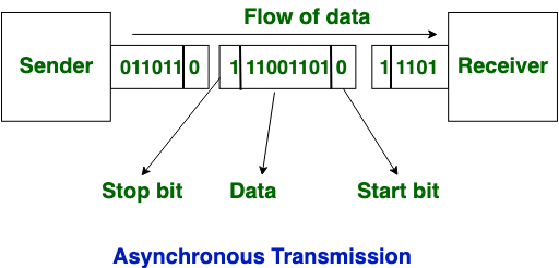
Asynchronous Transmission is also known as start/stop transmission, sends data from the sender to the receiver using the flow control method. It does not use a clock to synchronize data between the source and destination.
This transmission method sends one character or 8 bits at a time. In this method, before the transmission process begins, each character sends the start bit. After sending the character, it also sends the stop bit. With the character bits and start and stop bits, the total number of bits is 10 bits.
DIFFERENCES:
- Synchronous is a data transfer method in which a continuous stream of data signals is accompanied by timing signals whereas Asynchronous data transmission is a data transfer method in which the sender and the receiver use the flow control method.
- In, synchronous transmission method users need to wait until it sending finishes before getting a response from the server. On the contrary, Asynchronous transmission method users do not have to wait until sending completes before receiving a response from the server.
- Synchronous Transmission sends data in the form of blocks or frames while Asynchronous Transmission send data in the form of character or byte.
- Synchronous Transmission is fast. On the other hand, Asynchronous transmission method is slow.
- Synchronous Transmission is costly whereas Asynchronous Transmission is economical.