Unit-1
Q1) Write the goals of the network?
A1) Goals of Network
The following are the network's key objectives.
● Resource sharing: A computer network's primary goal is to accomplish this. It means that any computer on the network will share all of its programs, peripherals, and data with all other computers on the network, regardless of their physical locations. As a result, users at a great distance will share resources or view data on a device in the same way that local users do.
Load sharing is another type of resource sharing. That is, if necessary, a job can be done on several computers in a network by portioning it, which reduces time and load on each computer.
● Cost reduction: A second aim of networking is to save money. Sharing resources automatically lowers costs, allowing money to be saved.
● High reliability: Another aim is to ensure high reliability by providing many supply sources. For example, all files could be replicated on two or three computers, so that if one of them goes down, the others will still work.
● Improve performance: Another aim that is closely related is to improve the system's efficiency. As the workload on a machine increases, its output can be enhanced by adding one or more processors. For example, instead of replacing the device with a larger one that is more expansive, it is easier to add more processors to it at a lower cost and with less inconvenience to the consumer.
● Communication medium: Computer networks are an effective means of communication. A file that has been updated/modified on a network is instantly visible to all users on the network.
Q2) What are the applications of the network?
A2) Application of Network
The following are some examples of network applications in various fields.
Q3) Explain the types of networks?
A3) Types of Networks
A computer network is a set of computers linked together by a communication medium such as cable or wire.
The geographic area and number of computers that make up a network can be used to determine the scale of the network. It can range from a single computer in a single room to millions of devices distributed across the globe.
Based on their complexity, computer networks are divided into four categories:
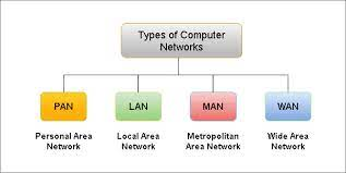
Fig 1: types of networks
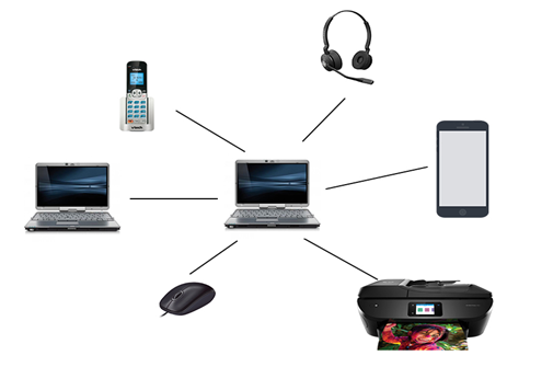
Fig 2: PAN
2. LAN: A Local Area Network (LAN) is a set of computers and peripheral devices linked in a small area, such as a classroom, laboratory, home, or office building. It's a popular network for sharing resources such as files, printers, games, and other software. Connecting computers and a printer in someone's home or office is the most basic form of LAN network. LAN will be used as one form of transmission medium in general.
It's a network of less than 5000 interconnected devices spread over several buildings.
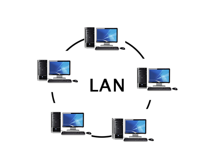
Fig 3: LAN
3. MAN: A Metropolitan Area Network, or MAN, is a computer network that spans a city, a college campus, or a small area. This network is far larger than a LAN, which is usually restricted to a single building or location. This form of network can cover a range of distances from a few miles to tens of miles, depending on the configuration.
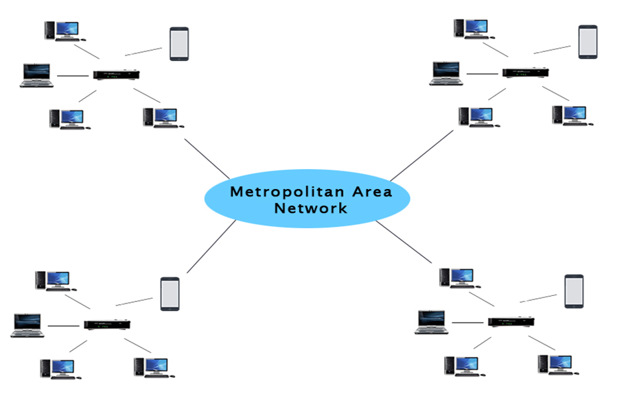
Fig 4: MAN
4. WAN: Another significant computer network that spans a vast geographical area is the WAN (Wide Area Network). A WAN network system may be a LAN link that uses telephone lines and radio waves to connect to other LANs. It is usually restricted to a single company or organization.
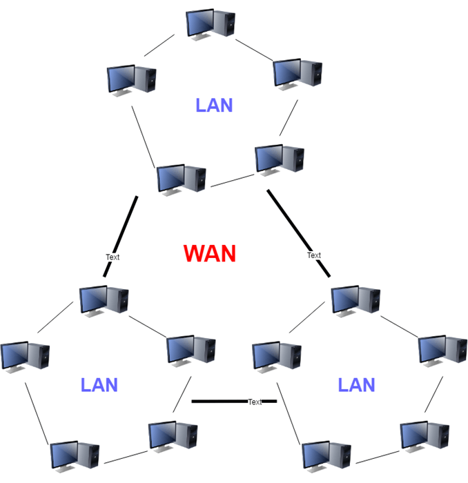
Fig 5: WAN
Q4) Write short notes on ISP?
A4) ISP
An internet service provider (ISP) is a corporation that provides both personal and business customers with internet access. For a charge, ISPs allow their customers to browse the web, shop online, conduct business, and communicate with family and friends.
Other services that ISPs can offer include email, domain registration, web hosting, and browser packages. Based on the services it provides, an ISP can also be referred to as an information service provider, a storage service provider, an internet service provider (INSP), or any combination of these terms.
During the mid-1990s, the number of ISPs grew to several thousand, and the bubble was in full swing. The internet economy arose as access opportunities expanded and speeds shifted away from slower dial-up connections. Customers can now get high-speed access via broadband technology via cable and digital subscriber line (DSL) modems, thanks to advances in provider technology.
ISPs typically give their customers the ability to communicate with one another through Internet email accounts, which are usually set up with several email addresses at the customer's discretion.
Other services can be offered, such as telephone and television services, as well as personal websites or home pages. Each ISP's services and service combinations can be special.
Internet service providers mainly provide their customers with internet access—basic access providers that only manage traffic between the user and the entire internet. However, depending on the customer's position and availability, additional resources could be included.
Among the programs available are:
● Email services
● Web hosting services
● Domain registration
● Browser and software packages
Q5) Describe Network structure and architecture?
A5) Network structure and architecture
Computer Network Architecture is defined as the physical and logical design of the software, hardware, protocols, and media of the transmission of data. Simply we can say that how computers are organized and how tasks are allocated to the computer.
The two types of network architectures are used:
● Peer-To-Peer network
● Client/Server network
Peer-To-Peer network
Peer-To-Peer network is a network in which all the computers are linked together with equal privilege and responsibilities for processing the data. Peer-To-Peer network is useful for small environments, usually up to 10 computers. Peer-To-Peer network has no dedicated server. Special permissions are assigned to each computer for sharing the resources, but this can lead to a problem if the computer with the resource is down.
Advantages of Peer-To-Peer Network:
It is less costly as it does not contain any dedicated server. If one computer stops working but, other computers will not stop working. It is easy to set up and maintain as each computer manages itself.
Disadvantages of Peer-To-Peer Network:
In the case of the Peer-To-Peer network, it does not contain the centralized system. Therefore, it cannot back up the data as the data is different in different locations. It has a security issue as the device is managed itself.
Client/Server Network
Client/Server network is a network model designed for the end users called clients, to access the resources such as songs, video, etc. from a central computer known as Server. The central controller is known as a server while all other computers in the network are called clients. A server performs all the major operations such as security and network management.
A server is responsible for managing all the resources such as files, directories, printers, etc. All the clients communicate with each other through a server. For example, if client1 wants to send some data to client 2, then it first sends the request to the server for the permission. The server sends the response to the client 1 to initiate its communication with the client 2.
Advantages of Client/Server network:
A Client/Server network contains the centralized system. Therefore, we can back up the data easily. A Client/Server network has a dedicated server that improves the overall performance of the whole system. Security is better in the Client/Server network as a single server administers the shared resources. It also increases the speed of the sharing resources.
Disadvantages of Client/Server network:
Client/Server network is expensive as it requires the server with large memory. A server has a Network Operating System (NOS) to provide the resources to the clients, but the cost of NOS is very high. It requires a dedicated network administrator to manage all the resources.
Q6) Explain OSI model?
A6) OSI Model
OSI stands for Open System Interconnection is a reference model that describes how information from a software application in one computer moves through a physical medium to the software application in another computer’s consists of seven layers, and each layer performs a particular network function’s model was developed by the International Organization for Standardization (ISO) in 1984, and it is now considered as an architectural model for the inter-computer communications.
The OSI model divides the whole task into seven smaller and manageable tasks. Each layer is assigned a particular task. Each layer is self-contained, so that tasks assigned to each layer can be performed independently.
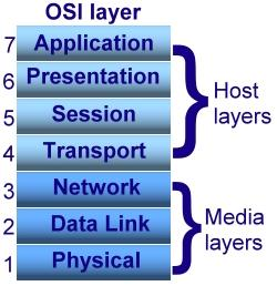
Fig 6: OSI model
The OSI model is divided into two layers: upper layers and lower layers. The upper layer of the OSI model mainly deals with the application related issues, and they are implemented only in the software. The application layer is closest to the end user. Both the end user and the application layer interact with the software applications. An upper layer refers to the layer just above another layer. The lower layer of the OSI model deals with the data transport issues. The data link layer and the physical layer are implemented in hardware and software. The physical layer is the lowest layer of the OSI model and is closest to the physical medium. The physical layer is mainly responsible for placing the information on the physical medium.
There are seven OSI layers.
Each layer has different functions. A list of seven layers are given below:
2. Data-Link Layer: The data link layer is in charge of message transmission from node to node. The main purpose of this layer is to ensure that data transfers from one node to another over the physical layer are error-free. It is DLL's duty to send a packet to the Host using its MAC address when it arrives in a network.
3. Network Layer: The network layer is responsible for data transmission between hosts on different networks. It also handles packet routing, which is the selection of the shortest path to transmit a packet from a large number of options. The network layer places the IP addresses of the sender and receiver in the header.
4. Transport Layer: The application layer receives services from the transport layer, and the network layer receives services from the transport layer. Segments are the units of data in the transport layer. It is in charge of the full message's delivery from beginning to end.
5. Session Layer: This layer is in charge of establishing connections, maintaining sessions, authenticating users, and ensuring security.
6. Presentation Layer: The Translation layer is also known as the Presentation layer. The data from the application layer is extracted and manipulated here so that it can be transmitted over the network in the appropriate format.
7. Application Layer : The Application layer, which is implemented by network applications, is at the very top of the OSI Reference Model stack of layers. These applications generate the data that must be sent over the network. This layer also acts as a window for application services to connect to the network and present the information they receive to the user.
Q7) What is the TCP/IP protocol suit?
A7) TCP/IP Protocol Suit
TCP/IP Reference Model is a four-layered suite of communication protocols. It was developed by the DoD (Department of Defence) in the 1960s. It is named after the two main protocols that are used in the model, namely, TCP and IP. TCP stands for Transmission Control Protocol and IP stands for Internet Protocol.
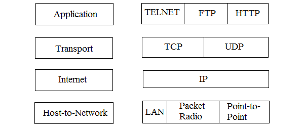
Fig 7: TCP/IP protocol suit
The four layers in the TCP/IP protocol suite are −
Host-to- Network Layer −It is the lowest layer that is concerned with the physical transmission of data. TCP/IP does not specifically define any protocol here but supports all the standard protocols.
Internet Layer −It defines the protocols for logical transmission of data over the network. The main protocol in this layer is Internet Protocol (IP) and it is supported by the protocols ICMP, IGMP, RARP, and ARP.
Transport Layer − It is responsible for error-free end-to-end delivery of data. The protocols defined here are Transmission Control Protocol (TCP) and User Datagram Protocol (UDP).
Application Layer − This is the topmost layer and defines the interface of host programs with the transport layer services. This layer includes all high-level protocols like Telnet, DNS, HTTP, FTP, SMTP, etc.
The advantages of TCP/IP protocol suite are
The disadvantages of the TCP/IP model are
Q8) Write the Network devices and components?
A8) Network devices and components
The major components used to install the program are computer network components. NIC, switch, cable, hub, router, and modem are all essential network components. Some network components can be removed depending on the type of network we need to install. The wireless network, for example, does not require the use of a cable.
The following are the main elements needed to set up a network:
NIC: The term "network interface card" refers to a computer's network interface card. A network interface card (NIC) is a hardware component that connects two computers on a network. It can transmit data at speeds ranging from 10,100 to 1000 Mb/s. The MAC address, also known as the physical address, is encoded on the network card chip and allocated by the IEEE to uniquely identify each network card. The PROM stores the MAC address (Programmable read-only memory).
Types of NIC
● Wired NIC: The Wired NIC can be found on the motherboard. To pass data, wired NICs use cables and connectors.
● Wireless NIC: The antenna for establishing a wireless network link is housed in the wireless NIC. The wireless NIC, for example, is used on a laptop computer.
Hub: A hub is a piece of hardware that splits a network link between multiple devices. When a device requests information from a network, the request is first sent via cable to the Hub. This request will be transmitted to the entire network by Hub. Both devices will search to see whether the request is theirs or not. Otherwise, the appeal would be ignored.
The Hub's operation uses more bandwidth and restricts the amount of data that can be sent. Hubs are no longer used and have been replaced by more modern computer network components such as switches and routers.
Switch: A switch is a computer network hardware device that links several computers. A Switch is more advanced than a Hub in terms of functionality. The Switch houses a modified table that determines whether or not data is transmitted. Based on the physical address in the incoming message, Switch sends the message to the correct destination.
Unlike the Hub, a Switch does not broadcast the message to the whole network. It identifies the computer to which the message will be sent. As a result, we may assume that the switch establishes a direct link between the source and the destination. It boosts the network's efficiency.
Router: A router is a hardware device that connects a local area network (LAN) to the internet. It receives, analyzes, and forwards incoming packets to a different network. A router is part of the OSI Reference Model's Layer 3 (Network layer).
The packet is forwarded by a router based on the details in the routing table. It selects the best route for packet transmission from among the available options.
Modem: A modem is a piece of hardware that enables a computer to link to the internet using an existing phone line. A modem is not built into the motherboard; instead, it is mounted in a PCI slot on the motherboard. Modulator/Demodulator is what it stands for. It uses telephone lines to transform digital data into an analog signal.
Q9) What do you mean by network topology design?
A9) Network Topology
Topology refers to the network's structure and how all of the elements are linked to one another. Physical and logical topology are the two forms of topology.
The geometric representation of all the nodes in a network is known as physical topology.
● Bus topology: The bus topology is set up in such a way that all of the stations are linked together by a single backbone cable. Each node is either connected to the backbone cable through a drop cable or is directly connected to it.
When a node wishes to send a message across the network, it does so by sending a message across the network. Regardless of whether the message has been answered, it will be received by all available stations in the network.
The bus topology is commonly used in regular networks such as 802.3 (ethernet) and 802.4 (wireless). In comparison to other topologies, the configuration of a bus topology is very straightforward. The backbone cable is thought of as a "single path" from which the message is sent to all of the stations.
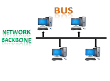
Fig 8: bus topology
● Ring topology: The topology of a ring is similar to that of a bus, but with connected ends. The node that receives the previous computer's message will retransmit to the next node. The data is unidirectional, meaning it only moves in one direction.
The data is continually flowed in a single loop, which is referred to as an infinite loop. It has no terminated ends, which means that each node is connected to the next and has no point of termination.
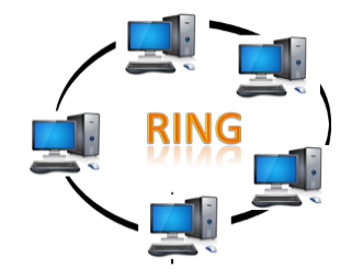
Fig 9: ring topology
● Star topology: The star topology is a network configuration in which each node is connected to a central hub, switch, or device. The central computer is referred to as a server, and the peripheral devices connected to it as clients.
The computers are connected via coaxial cable or RJ-45 cables. In a physical star topology, hubs or switches are primarily used as connection devices. The star topology is the most widely used network topology.
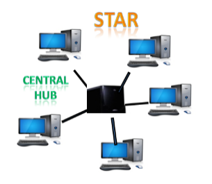
Fig 10: star topology
● Tree topology: Tree topology incorporates the advantages of both bus and star topologies. A tree topology is a system in which all computers are related to one another in a hierarchical manner.
A root node is the top-most node in a tree topology, and all other nodes are descendants of the root node. For data transmission, there is only one path between two nodes. As a result, it creates a parent-child hierarchy.
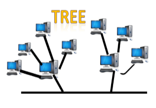
Fig 11: tree topology
● Mesh topology: Mesh technology is a network configuration in which computers are connected to one another through multiple redundant connections. There are many ways to get from one device to another. It is devoid of the turn, hub, or any central device that serves as a communication hub.
The mesh topology is exemplified by the Internet. Mesh topology is most commonly used in WAN deployments where communication failures are a major concern. Wireless networks commonly use the mesh topology.
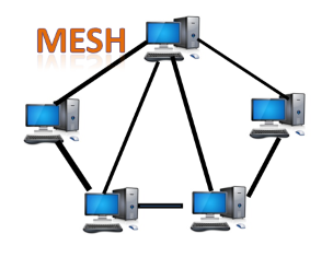
Fig 12: mesh topology
● Hybrid topology: Hybrid topology is the synthesis of many different topologies. A hybrid topology connects various links and nodes in order to transfer data. Hybrid topology is described as the combination of two or more different topologies, while similar topologies connecting to each other do not result in Hybrid topology.
For example, if a ring topology exists in one SBI bank branch and a bus topology exists in another SBI bank branch, connecting these two topologies would result in a Hybrid topology.
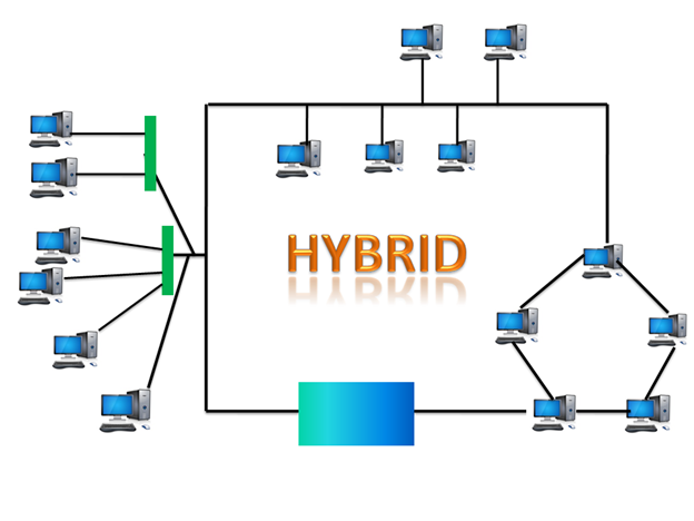
Fig 13: hybrid topology
Q10) Describe the types of connection?
A10) types of Connection
There are several different forms of networking connections between two endpoints. One of the most popular examples is home networks and the Internet. Many different types of devices and approaches are used to bind to these types of network architectures.
Connecting computers to these types of networks necessitates the use of a networking system to do so. Point-to-Point Connection and Multipoint Connection are the two types of computer network connections discussed on this page.
A packet (short message) will take a variety of routes to get from point A to point B. PPP (Point-to-Point Protocol) is a data link protocol that is widely used in networking to create a direct connection between two networking nodes. It has the ability to authenticate connections, encrypt transmissions, and compress data. Serial cable, phone line, trunk line, cellular telephone, advanced radio communications, and fiber optic links such as SONET are all examples of physical networks where PPP is used. PPP is often used to link to the Internet.
2. Multipoint connection: A multipoint connection is a connection that connects three or more devices together. Multi-drop configuration is another name for it. Broadcast Networks are networks that have a multipoint architecture.
A message or packet transmitted by any machine in a broadcast network is received by all other machines in the network. The address field in the packet determines the recipient. Any computer checks the packet's address field when it receives it. It processes the transmitted packet if it is for that specific machine; otherwise, it ignores it.
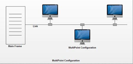
Fig 14: multipoint connection
Q11) What is transmission media?
A11) Transmission Media
Physical transmission media used in communications include twisted-pair cable, coaxial cable, and fiber-optic cable. These cables typically are used within or underground between buildings. Ethernet and token ring LANs often use physical transmission media.
Guided media
The physical medium by which signals are transmitted is referred to as the transmission medium. Bounded media is another name for it.
Types of guided media:
Twisted-Pair Cable
One of the more commonly used transmission media for network cabling and telephone systems is twisted-pair cable. Each twisted-pair wire consists of two separate insulated copper wires that are twisted together. The wires are twisted together to reduce noise. Noise is an electric- cal disturbance that can degrade communications.

Fig 15: twisted pair cable
Types of twisted pair cable
Coaxial Cable
Coaxial cable, often referred to as coax, consists of a single copper wire surrounded by at least three layers: (1) an insulating material, (2) a woven or braided metal, and (3) a plastic outer coating.
Cable television (CATV) network wiring often uses coaxial cable because it can be cabled over longer distances than twisted-pair cable. Most of today’s computer networks, however, do not use coaxial cable because other transmission media such as fiber-optic cable transmit signals at faster rates.

fig 16: coaxial cable
Types of coaxial cable
Fiber-Optic Cable
The core of a fiber-optic cable consists of dozens or hundreds of thin strands of glass or plastic that use light to transmit signals. Each strand, called an optical fiber, is as thin as a human hair. Inside the fiber-optic cable, an insulating glass cladding and a protective coating surround each optical fiber.

Fig 17: fiber optic cable
Fiber-optic cables have the following advantages over cables that use wire, such as twisted-pair and coaxial cables:
● Capability of carrying significantly more signals than wire cables
● Faster data transmission
● Less susceptible to noise (interference) from other devices such as a copy machine
● Better security for signals during transmission because they are less susceptible to noise
● Smaller size (much thinner and lighter weight)
Unguided media
The electromagnetic waves are transmitted without the use of any physical medium in an unguided transmission. Therefore, it is also known as wireless transmission.
Air is the medium through which electromagnetic energy can easily flow in unguided media.
Unguided transmission can be categorized into three types:
Radio waves: Radio waves are electromagnetic waves that travel through free space in all directions. Radio waves are omnidirectional, which means that the signals travel in all directions. Radio waves have a frequency range of 3 kHz to 1 kHz. The transmitting and receiving antennas are not compatible in the case of radio waves, so the wave transmitted by the sending antenna can be received by any receiving antenna.
Infrared: Infrared transmission is a wireless communication technology that works over short distances. Infrared waves with frequencies ranging from 300 GHz to 400 THz. It's used for short-range communication including data transfer between two mobile phones, TV remote control, and data transfer between a computer and a cell phone that's in the same room.
Q12) Explain Signal transmission and encoding?
A12) Signal transmission and encoding
The way data is transmitted through the medium is called signaling. It communicates through the use of electricity.
Types of signaling
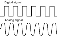
Fig 18: types of signaling
Digital signaling
Digital signaling is used in the majority of computer networks.
Encoding schemes are used to encode data in a digital signal.
● Current state encoding
● State transition encoding
Current state encoding
● The presence or absence of a signal characteristic or state is used to encrypt data in current-state encoding strategies.
● The network monitors the signal on a regular basis.
● The state-transition encoding approach represents data by using signal transitions.
● a 1 indicates the presence of a transition, while a 0 indicates the absence of a transition.
State transition encoding schemes
● Bipolar-Alternative Mark Inversion (AMI)
● Non-Return-to-Zero (NRZ)Manchester
● Differential Manchester
● Biphase Space (FM-0)
● Comparing Signaling Methods
Advantages of digital signaling
● Noise and interruption errors are reduced.
● Less costly equipment is used.
Disadvantages of digital signaling
● Attenuation is a problem that many people have.
Analog signaling
To send the digital data over an analog media, it needs to be converted into analog signal. There can be two cases according to data formatting.
Advantages of analog signaling
● Signal attenuation is lower than that of a digital signal.
● To maximize bandwidth, it can be multiplexed.
Disadvantages of analog signaling
● Noise and interference make it more vulnerable to mistakes.
Encoding
Encoding is the process of translating data, or a given sequence of characters, symbols, alphabets, or other characters, into a specific format for safe data transmission. Decoding is the method of extracting information from a transformed format in the opposite direction of encoding.
Encoding is the method of representing 1s and 0s in digital signals on a transmission connection using different patterns of voltage or current levels.
Unipolar, Polar, Bipolar, and Manchester are the most common forms of line encoding.
Encoding technique
Depending on the method of data conversion, data encoding techniques are classified as follows.
● Analog data to analog signal: This group includes analog signal modulation techniques such as Amplitude Modulation, Frequency Modulation, and Phase Modulation.
● Analog data to digital signal: Digitization is the term for this operation, which is carried out using Pulse Code Modulation PCM. As a result, it's just optical modulation. As previously mentioned, sampling and quantization are critical components in this process. The performance of Delta Modulation is superior to that of PCM.
● Digital data to analog signal: Amplitude Shift Keying ASK, Frequency Shift Keying FSK, Phase Shift Keying PSK, and other modulation techniques fall into this group.
● Digital data to digital signal: There are several ways to map digital data to digital signals.
Q13) Write the difference between OSI and TCP/IP model?
A13) Difference between OSI and TCP/IP Model
OSI Model | TCP/IP |
It stands for Open System Interconnection. | It stands for Transmission Control Protocol. |
The transport layer offers a guarantee for packet delivery in the OSI model.
| The distribution of packets is not guaranteed by the transport layer. Nonetheless, we may assume that it is a trustworthy model. |
The vertical method is used in this model. | The horizontal method is used in this model. |
It consists of 7 layers. | It consists of 4 layers. |
The OSI model was created by ISO (International Standard Organization). | ARPANET was the company that produced it (Advanced Research Project Agency Network). |
The network layer in this model offers both connection-oriented and connectionless services. | Only connectionless services are provided by the network layer.
|
This model isn't seen very much. | This model is quite popular. |
It allows devices such as routers, motherboards, switches, and other hardware to be standardized. | It does not provide devices with standardization. It allows computers to communicate with one another. |
Q14) Describe Network performance and transmission impairments?
A14) Network performance and transmission impairments
Network performance relates to the customer's perception of a network's service quality.
Since each network is unique in its nature and design, there are several different ways to assess its performance. Instead of measuring efficiency, it can be modeled and simulated; one example is using state transition diagrams to model queuing performance or using a Network Simulator.
The following steps are often regarded as crucial:
● Bandwidth: The maximum rate at which information can be transmitted is calculated in bits per second.
● Throughput: The rate at which data is transmitted is known as throughput.
● Latency: Latency is the time between when a signal is sent and when it is decoded by the receiver. It is primarily a function of the signal's transit time and the processing time at any nodes the information passes through.
● Jitter: Jitter variance in packet delay at the information receiver
● Error rate: The number of corrupted bits expressed as a percentage or fraction of the total sent is known as the error rate.
Transmission impairments
When a transmitting impairment causes the received signal to differ from the transmitted signal. Signal output would be harmed as a result of transmission problems.

Fig 19: transmission impairment
Attenuation: Attenuation refers to the loss of energy caused by the signal's intensity decreasing as the distance between them increases.
Distortion: When the form of a signal changes, it is said to be distorted. Different signals of different frequencies are analyzed for this form of distortion. Due to the fact that each frequency variable has its own propagation speed, they arrive at different times, resulting in delay distortion.
Noise: When data is sent over a transmission medium, an unwanted signal is mixed in, resulting in noise.
Q15) What is the switching technique?
A15) Switching Technique
In large networks, there can be multiple paths from sender to receiver. The switching technique will decide the best route for data transmission. Switching technique is used to connect the systems for making one-to-one communication.
Classification of switching techniques:
● Circuit Switching
Circuit switching is a switching technique that establishes a dedicated path between sender and receiver. In the Circuit Switching Technique, once the connection is established then the dedicated path will remain to exist until the connection is terminated. Circuit switching in a network operates in a similar way as the telephone works. A complete end-to-end path must exist before the communication takes place.
In case of circuit switching technique, when any user wants to send the data, voice, video, a request signal is sent to the receiver then the receiver sends back the acknowledgment to ensure the availability of the dedicated path. After receiving the acknowledgement, a dedicated path transfers the data. Circuit switching is used in public telephone networks. It is used for voice transmission. Fixed data can be transferred at a time in circuit switching technology.
Communication through circuit switching has 3 phases:
● Circuit establishment
● Data transfer
● Circuit Disconnect
Space Division Switches:
Space Division Switching is a circuit switching technology in which a single transmission path is accomplished in a switch by using a physically separate set of cross points. Space Division Switching can be achieved by using a crossbar switch. A crossbar switch is a metallic cross point or semiconductor gate that can be enabled or disabled by a control unit. The Crossbar switch is made by using the semiconductor. For example, Xilinx crossbar switch using FPGAs. Space Division Switching has high speed, high capacity, and no blocking switches. Space Division Switches can be categorized in two ways:
Crossbar Switch
The Crossbar switch is a switch that has no input lines and no output lines. The crossbar switch has 2 intersection points known as cross points.
Disadvantage of Crossbar switch:
The number of cross points increases as the number of stations is increased. Therefore, it becomes very expensive for a large switch. The solution to this is to use a multistage switch.
Multistage Switch
Multistage Switch is made by splitting the crossbar switch into the smaller units and then interconnecting them. It reduces the number of cross points. If one path fails, then there will be an availability of another path.
Advantages of Circuit Switching:
● In the case of Circuit Switching technique, the communication channel is dedicated.
● It has fixed bandwidth.
Disadvantages of Circuit Switching:
Once the dedicated path is established, the only delay occurs in the speed of data transmission. It takes a long time to establish a connection of approx. 10 seconds during which no data can be transmitted. It is more expensive than other switching techniques as a dedicated path is required for each connection. It is inefficient to use because once the path is established and no data is transferred, then the capacity of the path is wasted.
● Message switching
Message switching is a switching strategy in which a message is sent in its entirety and routed to intermediate nodes where it is processed and forwarded. A dedicated path between the sender and receiver is not established in the Message Switching technique.
The message's destination address is appended to it. Message Switching allows for dynamic routing through routing messages across intermediate nodes depending on the information contained in the message. Message switches are configured in such a way that the most effective routes are available.
● Packet switching
The packet switching strategy divides the message into smaller bits and sends them individually rather than sending it all at once. The message is broken down into smaller parts known as packets, each of which is assigned a unique number to mark its position in the receiving order.
The headers of each packet contain information such as the source address, destination address, and sequence number. Packets can take the shortest route possible through the network. At the receiving end, all of the packets are reassembled in the correct order. If one or more packets are missing or corrupted, the message will be sent again.
There are two approaches to Packet Switching:
● Datagram packet switching
● Virtual circuit switching
Q16) Define multiplexing?
A16) Multiplexing
Multiplexing is a method of combining and transmitting multiple data sources over a single channel. Multiplexing is the method of merging data streams, and the hardware used for multiplexing is known as a multiplexer.
Multiplexing is accomplished by the use of a computer known as a Multiplexer (MUX), which combines n input lines into a single output line. Many-to-one multiplexing is used, which means there are n input lines and one output line.
At the receiving end, a system called a Demultiplexer (DEMUX) is used to demultiplex the signal. DEMUX is a signal demultiplexer that separates a signal into its constituent signals (one input and n outputs). As a result, we can claim that demultiplexing is a one-to-many method.

Fig 20: multiplexing
Advantages of multiplexing:
● Over a single medium, multiple signals may be sent.
● A medium's bandwidth can be efficiently used.