Unit – 2
Link Layer
Q1) Explain framing?
A1) Framing
Data transmission at the physical layer entails the synchronized transmission of bits from the source to the destination. These bits are packed into frames by the data link layer.
The Data-link Layer encapsulates the packets from the Network Layer into frames. If the frame size gets too big, the packet can be split up into smaller frames. Flow control and error control are more effective with smaller frames.
Then it sends each frame to the hardware bit by bit. The data link layer at the receiver's end collects signals from hardware and assembles them into frames.
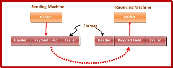
Fig 1: framing
Parts of the Framing
A frame has the following pieces −
● Frame header: It includes the frame's source and destination addresses.
● Payload field: It holds the message that will be sent.
● Trailer: It includes the bits for error detection and correction.
● Field: It denotes the start and end of the frame.

Fig 2: parts of frames
Types of Framing
There are two styles of framing: fixed sized framing and variable sized framing.
Fixed - size framing: The frame size is set in this case, so the frame length serves as a delimiter. As a result, no additional boundary bits are required to define the start and end of the frame.
Variable - size framing: The size of each frame to be transmitted can differ in this case. As a result, additional mechanisms are held to indicate the end of one frame and the start of the next.
It's a protocol that's used in local area networks.
In variable-sized framing, there are two ways to describe frame delimiters.
Length Field: The size of the frame is determined by a length field in this case. Ethernet makes use of it (IEEE 802.3).
End Delimiter: To decide the size of the frame, a pattern is used as a delimiter. Token Rings make use of it. If the pattern appears in the message, there are two options for dealing with the case.
● Byte - stuffing: To distinguish the message from the delimiter, a byte is crammed into it. Character-oriented framing is another term for this.
● Bit - stuffing: To distinguish the message from the delimiter, a pattern of bits of arbitrary duration is stuffed into it. This is often referred to as bit-oriented framing.
Q2) Write the error detecting technique?
A2) Error Detecting Technique
There are three major methods for identifying frame errors:
Parity Check
The parity check is performed by adding an extra bit to the data called the parity bit, which results in a number of 1s that is either even in even parity or odd in odd parity.
The sender counts the number of 1s in a frame and adds the parity bit in the following way when making it.
● Even parity: The parity bit value is 0 if the number of 1s is even. The parity bit value is 1 if the number of 1s is odd.
● Odd parity: The parity bit value is 0 if the number of 1s is odd. The parity bit value is 1 if the number of 1s is even.
The receiver counts the number of 1s in a frame as it receives it. If the count of 1s is even in an even parity search, the frame is accepted; otherwise, it is rejected. For odd parity search, a similar rule is used. The parity check is only good for detecting single bit errors.
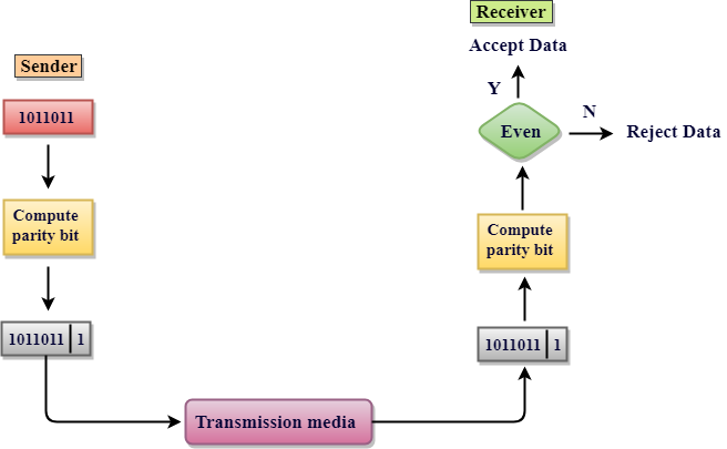
Fig 3: parity check
Checksum
The following procedure is used in this error detection scheme:
● Data is divided into frames or segments of a predetermined dimension.
● To get the sum, the sender adds the segments using 1's complement arithmetic. It then adds the sums together to get the checksum, which it sends along with the data frames.
● To get the number, the receiver adds the incoming segments and the checksum using 1's complement arithmetic, then complements it.
● The obtained frames are approved if the outcome is zero; otherwise, they are discarded.
Cyclic Redundancy Check (CRC)
CRC is a binary division of the data bits being sent by a fixed divisor agreed upon by the communicating machine. Polynomials are used to build the divisor.
Here, the sender divides the data segment by the divisor in binary. The remaining CRC bits are then appended to the end of the data segment. As a consequence, the resulting data unit is divisible by the divisor exactly.
The divisor is used by the receiver to separate the incoming data unit. The data unit is considered to be right and approved if there is no remainder. Otherwise, it's assumed that the data is tainted and will be denied.
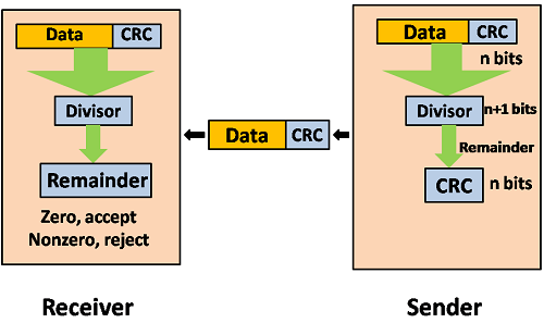
Fig 4: CRC
Q3) What is error correction technique?
A3) Error Correction Technique
Techniques for correcting errors determine the exact number of corrupted bits as well as their positions.
There are two main approaches.
2. Forward Error Correction: If the receiver detects an error in the incoming frame, error-correcting code is executed, and the actual frame is produced. This reduces the amount of bandwidth required for retransmission. In real-time systems, it is unavoidable. If there are so many faults, however, the frames must be present.
The four most popular error correction codes are as follows:
● Hamming Codes
● Binary Convolution Code
● Reed – Solomon Code
● Low-Density Parity-Check Code
Hamming Code
Algorithm of hamming code
● An information of 'd' bits is added to the redundant bits 'r' to form d+r.
● The location of each of the (d+r) digits is assigned a decimal value.
● The 'r' bits are placed in the positions 1, 2.....2k-1.
● At the receiving end, the parity bits are recalculated. The decimal value of the parity bits determines the position of an error.
Q4) Describe flow control?
A14) Flow Control
It's a series of instructions that tells the sender how much data they can send before the recipient becomes overwhelmed. The data is stored on a receiving computer with limited speed and memory.
As a result, before the limits are reached, the receiving system must be able to alert the transmitting device to temporarily halt transmission. It necessitates the use of a buffer, which is a memory block used to store data before it is processed.
Consider the case where the sender sends frames faster than the recipient can receive them. If the sender continues to send frames at a high pace, the receiver will eventually become overwhelmed and begin to lose frames. Introducing flow control may be the solution to this issue. Most flow control protocols provide a feedback mechanism that notifies the sender when the next frame should be transmitted.
Mechanism for flow control
● Stop and wait
● Sliding window
Stop and Wait
The following transformations are included in this protocol:
● The sender sends a frame and then waits for a response.
● When the receiver receives the frame, it gives the sender an acknowledgment frame.
● The sender recognizes that the recipient is able to consider the next frame after receiving the acknowledgment frame. As a result, it sends the next frame in the queue.
Advantages
The Stop-and-Wait approach is straightforward, as each frame is tested and accepted before sending the next.
Disadvantages
Since each frame must travel all the way to the recipient, and an acknowledgment must travel all the way until the next frame is sent, the stop-and-wait strategy is inefficient. Each frame sent and received consumes the entire connection traversal time.
Sliding Window
By allowing several frames to be transmitted before receiving an acknowledgement, this protocol increases the efficiency of the stop and wait protocol.
The following is a summary of the protocol's working principle:
● Both the sender and the receiver have windows, which are finite sized buffers. Depending on the buffer capacity, the sender and receiver agree on the number of frames to transmit.
● The sender sends a series of frames without waiting for an acknowledgement. It waits for acknowledgement after its sending window has been filled. It advances the window and transmits the next frames based on the amount of acknowledgements received.
Sender Window
The sender window comprises n-1 frames at the start of a transmission, and when they are sent out, the left boundary shifts inward, shrinking the window's dimension.
The sender window extends to the number equal to the number of frames acknowledged by ACK until the ACK has arrived.
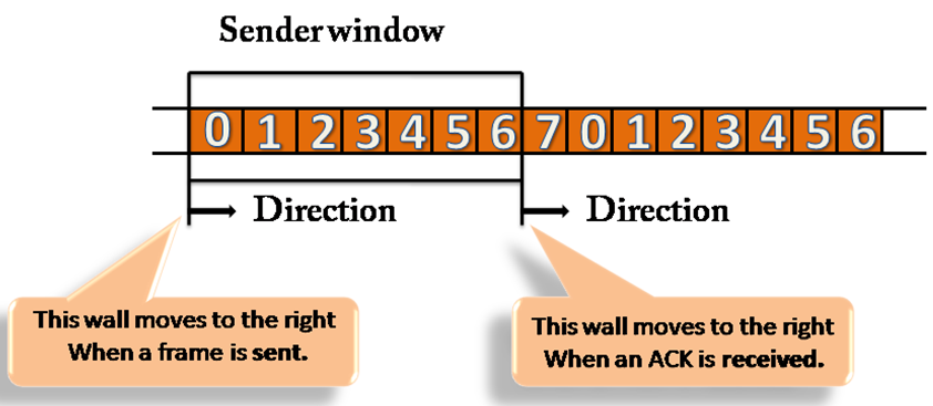
Fig 5: sender window
Receiver Window
The receiver window does not contain n frames at the start of transmission, but it does contain n-1 spaces for frames. The size of the window shrinks when the new frame arrives. The receiver window indicates the maximum number of frames that can be sent before an ACK is sent, not the number of frames received.
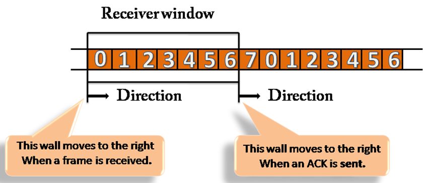
Fig 6: receiver window
Q5) Define channel allocation?
A5) Channel Allocation
When there is more than one user who desires to access a shared network channel, an algorithm is deployed for channel allocation among the competing users. The network channel may be a single cable or optical fiber connecting multiple nodes, or a portion of the wireless spectrum. Channel allocation algorithms allocate the wired channels and bandwidths to the users, who may be base stations, access points or terminal equipment.
Channel Allocation may be done using two schemes −
● Static Channel Allocation
● Dynamic Channel Allocation
1) Static Channel Allocation
In the static channel allocation scheme, a fixed portion of the frequency channel is allotted to each user. For N competing users, the bandwidth is divided into N channels using frequency division multiplexing (FDM), and each portion is assigned to one user.
This scheme is also referred to as fixed channel allocation or fixed channel assignment. In this allocation scheme, there is no interference between the users since each user is assigned a fixed channel. However, it is not suitable in case of a large number of users with variable bandwidth requirements.
2) Dynamic Channel Allocation
In the dynamic channel allocation scheme, frequency bands are not permanently assigned to the users. Instead, channels are allotted to users dynamically as needed, from a central pool. The allocation is done considering a number of parameters so that transmission interference is minimized. This allocation scheme optimizes bandwidth usage and results in faster transmissions. Dynamic channel allocation is further divided into centralized and distributed allocation.
Q6) Explain Multiple access protocols?
A6) Multiple access protocols
Data Link Layer
The data link layer is used in a computer network to transmit the data between two devices or nodes. It divides the layer into parts such as data link control and the multiple access resolution/protocol. The upper layer has the responsibility to flow control and the error control in the data link layer, and hence it is termed as logical of data link control. Whereas the lower sub-layer is used to handle and reduce the collision or multiple access on a channel. Hence it is termed as media access control or the multiple access resolutions.
Data Link Control
A data link control is a reliable channel for transmitting data over a dedicated link using various techniques such as framing, error control and flow control of data packets in the computer network.
What is a multiple access protocol?
When a sender and receiver have a dedicated link to transmit data packets, the data link control is enough to handle the channel. Suppose there is no dedicated path to communicate or transfer the data between two devices. In that case, multiple stations access the channel and simultaneously transmit the data over the channel. It may create collisions and cross talk. Hence, the multiple access protocol is required to reduce the collision and avoid crosstalk between the channels.
For example, suppose that there is a classroom full of students. When a teacher asks a question, all the students (small channels) in the class start answering the question at the same time (transferring the data simultaneously). All the students respond at the same time due to which data overlap or data is lost. Therefore it is the responsibility of a teacher (multiple access protocol) to manage the students and give them one answer.
Following are the types of multiple access protocol that is subdivided into the different process as:
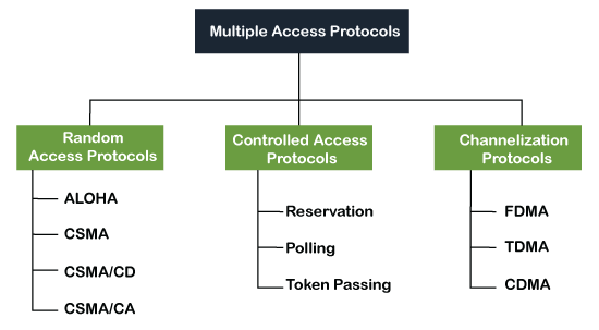
Fig 7: Types of multiple access protocol
A. Random Access Protocol
In this protocol, all the stations have the equal priority to send the data over a channel. In the random-access protocol, one or more stations cannot depend on another station nor any station control another station. Depending on the channel's state (idle or busy), each station transmits the data frame. However, if more than one station sends the data over a channel, there may be a collision or data conflict. Due to the collision, the data frame packets may be lost or changed. And hence, it does not receive by the receiver end.
Following are the different methods of random-access protocols for broadcasting frames on the channel.
● Aloha
● CSMA
● CSMA/CD
● CSMA/CA
Q7) What is aloha?
A7) ALOHA
It is designed for wireless LAN (Local Area Network) but can also be used in a shared medium to transmit data. Using this method, any station can transmit data across a network simultaneously when a data frameset is available for transmission.
Aloha Rules

Fig 8: Types of ALOHA
Pure Aloha
Whenever data is available for sending over a channel at stations, we use Pure Aloha. In pure Aloha, when each station transmits data to a channel without checking whether the channel is idle or not, the chances of collision may occur, and the data frame can be lost. When any station transmits the data frame to a channel, the pure Aloha waits for the receiver's acknowledgment. If it does not acknowledge the receiver ends within the specified time, the station waits for a random amount of time, called the backoff time (Tb). And the station may assume the frame has been lost or destroyed. Therefore, it retransmits the frame until all the data are successfully transmitted to the receiver.
As we can see in the figure above, there are four stations for accessing a shared channel and transmitting data frames. Some frames collide because most stations send their frames at the same time. Only two frames, frame 1.1 and frame 2.2, are successfully transmitted to the receiver end. At the same time, other frames are lost or destroyed. Whenever two frames fall on a shared channel simultaneously, collisions can occur, and both will suffer damage. If the new frame's first bit enters the channel before finishing the last bit of the second frame. Both frames are completely finished, and both stations must retransmit the data frame.
Slotted Aloha
The slotted Aloha is designed to overcome the pure Aloha's efficiency because pure Aloha has a very high possibility of frame hitting. In slotted Aloha, the shared channel is divided into a fixed time interval called slots. So that, if a station wants to send a frame to a shared channel, the frame can only be sent at the beginning of the slot, and only one frame is allowed to be sent to each slot. And if the stations are unable to send data to the beginning of the slot, the station will have to wait until the beginning of the slot for the next time. However, the possibility of a collision remains when trying to send a frame at the beginning of two or more station time slot.
Q8) What do you mean by csma?
A8) CSMA
CSMA (Carrier Sense Multiple Access)
It is a carrier sense multiple access based on media access protocol to sense the traffic on a channel (idle or busy) before transmitting the data. It means that if the channel is idle, the station can send data to the channel. Otherwise, it must wait until the channel becomes idle. Hence, it reduces the chances of a collision on a transmission medium.
CSMA Access Modes
1-Persistent: In the 1-Persistent mode of CSMA that defines each node, first sense the shared channel and if the channel is idle, it immediately sends the data. Else it must wait and keep track of the status of the channel to be idle and broadcast the frame unconditionally as soon as the channel is idle.
Non-Persistent: It is the access mode of CSMA that defines before transmitting the data, each node must sense the channel, and if the channel is inactive, it immediately sends the data. Otherwise, the station must wait for a random time (not continuously), and when the channel is found to be idle, it transmits the frames.
P-Persistent: It is the combination of 1-Persistent and Non-persistent modes. The P-Persistent mode defines that each node senses the channel, and if the channel is inactive, it sends a frame with a P probability. If the data is not transmitted, it waits for a (q = 1-p probability) random time and resumes the frame with the next time slot.
O- Persistent: It is an O-persistent method that defines the superiority of the station before the transmission of the frame on the shared channel. If it is found that the channel is inactive, each station waits for its turn to retransmit the data.
CSMA/ CD
It is a carrier sense multiple access/ collision detection network protocol to transmit data frames. The CSMA/CD protocol works with a medium access control layer. Therefore, it first senses the shared channel before broadcasting the frames, and if the channel is idle, it transmits a frame to check whether the transmission was successful. If the frame is successfully received, the station sends another frame. If any collision is detected in the CSMA/CD, the station sends a jam/ stop signal to the shared channel to terminate data transmission. After that, it waits for a random time before sending a frame to a channel.
CSMA/ CA
It is a carrier sense multiple access/collision avoidance network protocol for carrier transmission of data frames. It is a protocol that works with a medium access control layer. When a data frame is sent to a channel, it receives an acknowledgment to check whether the channel is clear. If the station receives only a single (own) acknowledgment, that means the data frame has been successfully transmitted to the receiver. But if it gets two signals (its own and one more in which the collision of frames), a collision of the frame occurs in the shared channel. Detects the collision of the frame when a sender receives an acknowledgment signal.
Q9) Explain FDMA, TDMA, CDMA?
A9) FDMA
It is a frequency division multiple access (FDMA) method used to divide the available bandwidth into equal bands so that multiple users can send data through a different frequency to the subchannel. Each station is reserved with a particular band to prevent the crosstalk between the channels and interferences of stations.
TDMA
Time Division Multiple Access (TDMA) is a channel access method. It allows the same frequency bandwidth to be shared across multiple stations. And to avoid collisions in the shared channel, it divides the channel into different frequency slots that allocate stations to transmit the data frames. The same frequency bandwidth into the shared channel by dividing the signal into various time slots to transmit it. However, TDMA has an overhead of synchronization that specifies each station's time slot by adding synchronization bits to each slot.
CDMA
The code division multiple access (CDMA) is a channel access method. In CDMA, all stations can simultaneously send the data over the same channel. It means that it allows each station to transmit the data frames with full frequency on the shared channel at all times. It does not require the division of bandwidth on a shared channel based on time slots.
If multiple stations send data to a channel simultaneously, their data frames are separated by a unique code sequence. Each station has a different unique code for transmitting the data over a shared channel. For example, there are multiple users in a room that are continuously speaking. Data is received by the users if only two-person interact with each other using the same language. Similarly, in the network, if different stations communicate with each other simultaneously with different code language.
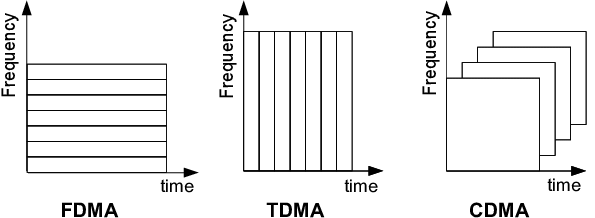
Fig 9: FDMA, TDMA, CDMA
Q10) Define LAN standard?
A10) LAN Standards
Each network has its own set of rules and guidelines. As a result, protocols are used in network technology to control network-to-network communication. There are several different protocols, but Ethernet and Token Ring are the most common protocols used in the OSI data link layer in LANs.
Ethernet
The most well-known form of local area network is Ethernet, which is commonly used in offices, home offices, and businesses. IEEE 802.3 is the Ethernet standard. The communication medium for Ethernet is usually coaxial cable, but there can also be various grades of twisted-pair cable.
Token Ring
Token Ring is a network that uses a star or ring topology to link computers. It was created by the IBM Corporation. To allow computers to enter the network, a token ring will be passed through the network. IEEE 802.5 is the standard for Token Ring networks. A token bit will be passed around the ring from one device to the next.
The data would connect to the token and transfer to the next device if the computer wishes to send data. It must continue to travel via the network's machines before it reaches its destination. The token ring will simply transfer to the next computer if the computer does not want to send any data.
Q11) Write about bridges and switches?
A11) Bridges
A data link layer bridge joins together several LANs (local area networks) to form a larger network. Network bridging is the term for the method of aggregating networks. A bridge links the various components to make them look as if they are all part of the same network.
Bridges only function at the OSI model's Physical and Data Link layers. By sitting between two physical network segments and controlling the flow of data between them, bridges are used to separate larger networks into smaller sections.
They pass frames using hardware Media Access Control (MAC) addresses. Bridges can forward or block data crossing by looking at the MAC addresses of the devices connected to each segment. Bridges may also be used to link two physical LANs together to create a larger logical LAN.
A bridge is used to link the two points in the diagram below.
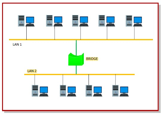
Fig 10: bridges
Switches
A switch is a networking system that connects various network devices, such as computers, printers, and servers, inside a small business network to exchange information and resources. The linked devices can exchange data and information and communicate with each other thanks to a switch.
Switches play a more intelligent role than hubs in most cases. A switch is a network device with multiple ports that improves network performance. The switch keeps minimal routing details about internal network nodes and makes connections to networks such as hubs and routers. Switches are commonly used to bind LAN strands.
In the OSI model, a switch can operate at either the Data Link layer or the Network layer. A multilayer switch is one that can run on both layers, meaning it can be used as a switch and a router. A multilayer switch is a high-capacity system that uses the same routing protocols as routers.
Switches also enhance network security by making it more difficult to inspect virtual circuits with network monitors. We can't create a small business network or link devices inside a building or campus without a switch.
Advantages of switches
● It increases the network's usable bandwidth.
● It has the ability to bind directly to workstations or smartphones.
● Improves the network's consistency.
● Switched networks have fewer frame collisions because switches provide a collision domain for each network.
● It aids in the reduction of burden on individual hosts, such as PCs.
Q12) Write the difference between the bridge and switch?
A12) Difference between bridge and switch
Switch | Bridge |
It is a system that is responsible for channeling data from different input ports to a specific output port, from which the data will be sent to the desired destination. | It is a system that divides a single network into multiple network segments.
|
Buffers are present in a turn.
| A buffer may or may not be present on a bridge. |
A switch can have a large number of ports. | A bridge can only have two or four ports. |
A switch performs the job of error testing. | The error checking cannot be done by a bridge. |
The packet forwarding is done by the switch using hardware such as ASICS, so it is hardware dependent. | The packet forwarding is done by software, so the bridge is software-based. |
In the case of a turn, the switching method may be stored, forward, fragment free, or cut through. | In the case of a bridge, the switching method is store and forward.
|
Q13) What is the difference between FDMA, TDMA and CDMA?
A13) Difference between FDMA, TDMA and CDMA
FDMA | TDMA | CDMA |
FDMA stands for Frequency Division Multiple Access. | TDMA stands for Time Division Multiple Access. | CDMA stands for Code Division Multiple Access. |
This involves the sharing of bandwidth among different stations. | Just the allocation of satellite transponder time takes place in this.
| This allows for the sharing of both bandwidth and time between different stations. |
There is no need for a codeword. | There is no need for a codeword. | A codeword is needed. |
There is no need for synchronization. | It is important to maintain synchronization. | There is no need for synchronization. |
The data flow is slow.
| The data flow is moderate. | Data is being produced at a rapid pace. |
This involves the sharing of bandwidth among different stations.
| Just the allocation of satellite transponder time takes place in this.
| This allows for the sharing of both bandwidth and time between different stations. |
Continuous signal is the data transfer mode. | Signal bursts are used to transmit data. | The optical signal is used for data transmission. |