Unit-3
Software Design
Q1) Explain pseudocode and flowchart?
A1) Pseudo code
“Code” refers to the instructions written in a programming language, and “pseudo” means imitation or fake. Both the preliminary and comprehensive design phases will benefit from pseudocode notation.
Advantages of pseudocode
The following are some of the benefits of pseudo-code:
● When opposed to converting a flowchart or decision table, converting pseudo-code to a programming language is much simpler.
● As compared to a flowchart, it is easier to change the pseudocode of program logic whenever changes are needed.
● Writing pseudo-code takes a lot less time and effort than writing a flowchart.
● Pseudo-code is easier to write than writing a program in a programming language because pseudo-code as a method has only a few rules to follow.
Disadvantages of pseudocode
The following are some of the drawbacks of pseudocode:
● In contrast to flowcharts, pseudocode does not provide a graphic representation of program logic.
● When using pseudo-code, there are no set rules to obey. Since different programmers write pseudo-code in their own way, communication issues arise due to a lack of standardization.
● It is more difficult for a novice to follow the logic or write pseudo-code than it is to follow a flowchart.
Flow Chart
A flowchart is a useful tool for representing the control flow in a program. A flowchart is a visual representation of an algorithm that uses symbols to depict the operations and decisions that a machine must make in order to solve a problem. The actual instructions are written using simple statements inside symbols / boxes. Strong lines with arrow marks link these boxes, indicating the flow of operations in a series.
In reality, when writing a program, flowcharts are the plan to follow. Expert programmers will not need to draw flowcharts while writing programs. However, it is recommended that a beginner draw a flowchart before writing, as this will reduce the amount of errors and omissions.
Q2) Describe Design Structure Chart?
A2) Design Structure Chart
During architectural design, structure charts are used to record a system's hierarchical frameworks, parameters, and interconnections.
It divides a computer into black boxes. A black box means that the user is aware of the features without being aware of the internal design. A black box is given inputs and acceptable outputs are provided by the black box. Since facts are withheld from those who have no need or desire to explore, this definition decreases uncertainty. As a result, systems are simple to build and manage.
As seen below, black boxes are organized in a hierarchical format.
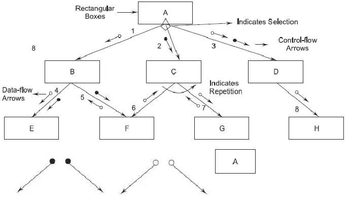
Fig 1: Hierarchical format of a structure chart
The top-level modules communicate with the lower-level modules. The lines between the rectangular boxes reflect the connections between modules. The components are typically read from left to right, from top to bottom. A hierarchical numbering scheme is used to number modules. There is only one module called the root at the top of every structure map.
Basic Building Blocks of a Structure Chart:
The following are the basic components of a structure chart:
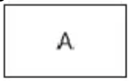
Fig 2: rectangular box
2. Arrow: An arrow connecting two modules indicates that power is transferred from one module to the other in the direction of the connecting arrow during program execution.

Fig 3: arrows
3. Data - flow Arrow: Data-flow arrows indicate that named data flows in the direction of the arrow from one module to the next.
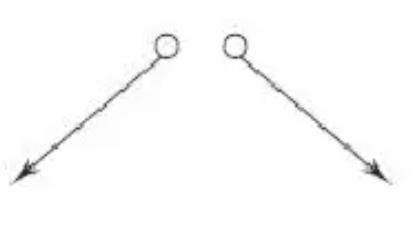
Fig 4: data - flow arrow
4. Library Module: The most common type of module is the library module, which is depicted as a rectangle with double edges. A library module is created when a module is used by a large number of other modules.
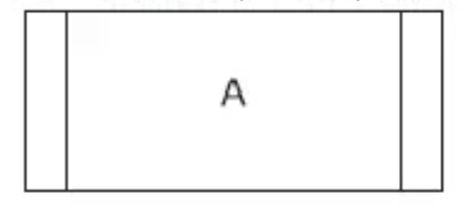
Fig 5: library module
5. Selection: The diamond symbol denotes that one of several modules associated with the diamond symbol is invoked based on the fulfillment of the condition written in the diamond symbol.
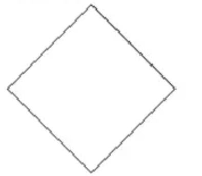
Fig 6: selection
6. Repetitions: A loop around the control-flow arrows indicates that the modules are called again and again.
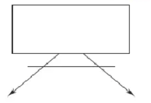
Fig 7: repetition
Q3) Write short notes on modularization?
A3) Modularization
The word module is defined in a variety of ways. They range from "a module is a FORTRAN subroutine" to "a module is an ADA package" to "a module is an individual programmer's job assignment." All of these concepts are right in the sense that modular structures consist of a set of abstractions, each of which handles a specific aspect of the problem being solved. A modular system is made up of well-defined, manageable units that have well-defined interfaces.
Modularity improves concept transparency, which makes software product execution, debugging, testing, documentation, and maintenance easier.
Desirable Properties of modular systems include
● Each abstraction's work serves a single, well-defined purpose.
● Each feature only works for one major data structure at a time.
● Global data is shared selectively by functions. It's simple to spot all the routines that share a common data structure.
● The data structure being manipulated encapsulates functions that manipulate instances of abstract data types.
The modularity of most engineering processes and products is critical. In the automotive industry, for example, automobiles are constructed by putting together building blocks that have been planned and built separately. Furthermore, components are often reused from model to model, often with slight modifications. Most manufacturing processes are basically modular, consisting of job packages that are combined in simple ways to achieve the desired result (sequentially or overlapping).
Q4) Define coupling?
A4) Coupling
Coupling is the measure of the interdependence of one module to another Modules should have low coupling. Low coupling minimizes the "ripple effect" where changes in one module cause errors in other modules.
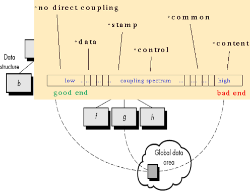
Fig 8: coupling
Types of Coupling
There are 6 types of coupling in the modules are
● No direct Coupling – These are independent modules and so are not really components of a single system. For e.g., this occurs between modules a and d.
● Data Coupling – Two modules are data coupled if they communicate by passing parameters. This has been told to you as a "good design principle" since day one of your programming instruction. For e.g., this occurs between module a and c.
● Stamp Coupling – Two modules are stamp coupled if they communicate via a passed data structure that contains more information than necessary for them to perform their functions. For e.g., this occurs between modules b and a.
● Control Coupling – Two modules are control coupled if they communicate using at least one "control flag". For e.g., this occurs between modules d and e.
● Common Coupling – Two modules are commonly coupled if they both share the same global data area. Another design principle you have been taught since day one: don't use global data. For e.g., this occurs between modules c, g and k.
● Content Coupling – Two modules are content coupled if:
■ One module changes a statement in another (Lisp was famous for this ability).
■ One module references or alters data contained inside another module.
■ One module branches into another module. For e.g., this occurs between modules b and f.
Q5) Write about cohesion?
A5) Cohesion
Cohesion is the measure of strength of the association of elements within a module. Modules whose elements are strongly and genuinely related to each other are desired. A module should be highly cohesive.
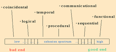
Fig 9: cohesion
Types of Cohesion
There are 7 types of cohesion in a module
● Coincidental Cohesion – A module has coincidental cohesion if its elements have no meaningful relationship to one another. It happens when a module is created by grouping unrelated instructions that appear repeatedly in other modules.
● Logical Cohesion – A logically cohesive module is one whose elements perform similar activities and in which the activities to be executed are chosen from outside the module. Here the control parameters are passed between those functions. For example, Instructions grouped together due to certain activities, like a switch statement. For ex. A module that performs all input & output operations.
● Temporal Cohesion – A temporally cohesive module is one whose elements are functions that are related in time. It occurs when all the elements are interrelated to each other in such a way that they are executed a single time. For ex. A module performing program initialization.
● Procedural Cohesion – A procedurally cohesive module is one whose elements are involved in different activities, but the activities are sequential. Procedural cohesion exists when processing elements of a module are related and must be executed in a specified order. For example, Do-while loops.
● Communication Cohesion – A communicationally cohesive module is one whose elements perform different functions, but each function references the same input information or output. For example, Error handling modules.
● Sequential Cohesion – A sequentially cohesive module is one whose functions are related such that output data from one function serves as input data to the next function. For example, deleting a file and updating the master record or function calling another function.
● Functional Cohesion – A functionally cohesive module is one in which all of the elements contribute to a single, well-defined task. Object-oriented languages tend to support this level of cohesion better than earlier languages do. For example, When a module consists of several other modules.
Q6) What do you mean by Function Oriented Design?
A6) Function Oriented Design
There are also two stages to the design process for software systems. At the first step, the emphasis is on determining which modules, based on SRS (Software Requirement Specification) are necessary for the system and how the modules should be interconnected.
Function Oriented Design is a software design approach in which the design is broken down into a series of interacting units in which each unit has a clearly specified function.
Procedure:
Start with an overview of what the software / programme does at a high level. Refine each element of the description one at a time by defining the functionality of each part in greater detail. The top-down structure contributes to these points.
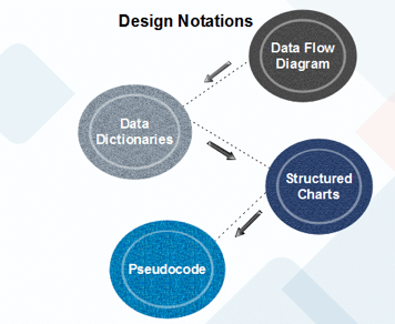
Fig 10: Design strategy
Function Oriented design strategies:
The following are Feature Driven Design Strategies:
● Data Flow Diagram: For any process or system, a data flow diagram (DFD) maps out the information flow. To display data inputs, outputs, storage points and the routes between each destination, it uses specified symbols such as rectangles, circles and arrows, plus short text labels.
● Data Dictionary: Data dictionaries are simply repositories that store all of the data items specified in DFDs with details. Data dictionaries contain data objects at the demand level. Item Name, Aliases (Other Item Names), Description/Purpose, Related Data Objects, Set of Values, Data Structure Definition/Form are the data dictionaries.
● Structure Chart: The hierarchical representation of the scheme divides the structure into black boxes (functionality is known to users but inner details are unknown). From top to bottom and left to right, components are read. The so-called module is regarded as a black box when a module calls another, passing the necessary parameters and obtaining results.
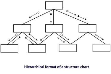
Fig 11: Structure chart
● Pseudo Code: In short English, Pseudo Code is a device description like phrases that explain the function. Keywords and indentations are used. For flow maps, pseudo codes are used as a substitute. It reduces the required amount of documentation.
Using pseudo-code, the designer uses short, succinct, English language stages to define device features organized by keywords such as If-Then-Else, While-Do, and End.
Q7) Explain object oriented design?
A7) Object Oriented Design
Object oriented design deals around the entities and their properties instead of functions involved in the software system. This design pattern focuses on entities and its properties. The whole concept of software solution revolves around the used entities.
Let us see the important concepts of Object Oriented Design:
● Objects - All entities included in the solution design are known as objects. For example, people, banks, industry and customers are treated as objects. Every entity has some attributes linked to it and has some methods to perform on the attributes.
● Classes - A class is a generalized description of an object. An object is an instance of a class. Class defines all the attributes, which an object can have and methods, which defines the functionality of the object. In the solution design, attributes are saved as variables and functionalities are defined by use of methods or procedures.
● Encapsulation - In OOD, the attributes (data variables) and methods (operation on the data) are wrapped together is called encapsulation. Encapsulation not only wraps important information of an object together, but also binds access of the data and methods from the outside world. This is called information hiding.
● Inheritance - OOD allows similar classes to heap (stack) up in hierarchical manner where the lower or sub-classes can import, implement and re-use allowed variables and methods from their immediate super classes. This property of OOD is known as inheritance. This makes it simpler to define specific classes and to create generalized classes from particular ones.
● Polymorphism - OOD languages provide a tool where methods performing similar tasks but vary in arguments, can be given the same name. This is called polymorphism, which allows a single interface performing tasks of different types. Depending upon how the function is called, the respective portion of the code gets executed.
Q8) Describe top-down and bottom-up design?
A8) Top-Down Design
We know that a system consists of more than one sub-systems and it consists of a number of elements. Further, these sub-systems and elements may have their one set of sub-system and elements and develop hierarchical structure in the system.
Top-down designs take the complete software system as one entity and then break-down it to achieve more than one sub-system or element based on some properties. Each sub-system or element is then considered as a system and broken down further. This process keeps on running until the lowest level of the system in the top-down hierarchy is accomplished.
Top-down design begins with a generalized model of a system and keeps on defining the more specific part of it. When all elements are composed the whole system comes into play. Top-down design is more satisfactory when the software solution needs to be designed from scratch and specific details are not known.
Bottom - Up Design
The bottom up design model begins with most specific and basic elements. It proceeds with composing higher level elements by using basic or lower level elements. It keeps developing higher level elements until the desired system is not evolved as one single element. With each higher level, the amount of abstraction is increased. Bottom-up strategy is more satisfactory when a system needs to be designed from some pre-existing system, where the basic primitives can be used in the new system.
Both, top-down and bottom-up approaches are impractical individually. Instead, a good combo of both is used.
Q9) What is Halestead’s Software Science?
A9) Halestead’s Software Science
Computer technology is distinct from computer science, according to Halstead (1977). Any programming task, according to software science, consists of selecting and arranging a finite number of program "tokens," which are simple syntactic units that can be distinguished by a compiler. According to software science, a computer program is a list of tokens that can be known as operators or operands.
The following are the basic measurements of Halstead's software science:

Halstead developed a system of equations based on these primitive measures that expressed the total vocabulary, overall program length, potential minimum volume for an algorithm, actual volume (number of bits required to specify a program), program level (a measure of software complexity), program difficulty, and other features including development effort and projected number.
The following are some of Halstead's main equations:
Vocabulary ( n ) |
|
Length ( N ) |
|
Volume ( V ) |
|
Level ( L ) |
|
Difficulty ( D ) (inverse of level) |
|
Effort (E) |
|
Faults ( B ) |
|
where V * represents the smallest volume represented by a built-in function performing the entire program's task, and S * represents the average number of mental discriminations (decisions) between errors.
The work of Halstead has had a major effect on machine measurement. His work was crucial in bringing metrics studies to the attention of computer scientists. Software technology, on the other hand, has been a source of contention and criticism since its inception. Methodology, equation derivations, human memory models, and other topics have also been criticized.
Q10) What do you mean by Function point (FP)Based Measures?
A10) Function point (FP)Based Measures
A Function Point (FP) is a measurement unit that expresses the amount of business functionality that a customer is provided with by an information system (as a product). Software size tests FPs. They are commonly accepted for practical sizing as an industry standard.
A combination of software features is based on a
● External input and output
● User interactions
● External interface
● Files used by the system
Each of these is correlated with one weight. By multiplying each raw count by weight and summing all values, the FP count is computed. The FP count is changed by the project's complexity.
FPs can be used to estimate a given LOC based on the average number of LOCs per FP.
● LOC = AVC * number of function point
● (AVC - language dependent factor)
Q11) Explain Cyclomatic Complexity Measures: Control Flow Graphs?
A11) Cyclomatic Complexity Measures: Control Flow Graphs
Cyclomatic complexity is used to measure logical complexity of a program. When used in the basis path testing method, the value computed for Cyclomatic complexity defines the number of independent paths in the program to give upper bound for the number of tests that must be executed at least once.
An independent path is any path through the program that introduces at least one new set of processing statements or a new condition. When stated in terms of a flowgraph, an independent path must move along at least one edge that has not been traversed before the path is defined.
For example, a set of independent paths (B) for the flow graph (A) illustrated in Figures below.
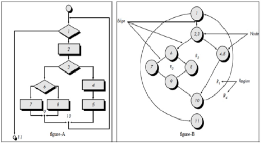
Fig 12: flow graph and independent graph
path 1: 1-11
path 2: 1-2-3-4-5-10-1-11
path 3: 1-2-3-6-8-9-10-1-11
path 4: 1-2-3-6-7-9-10-1-11
Note that each new path introduces a new edge. The path is not considered to be an independent path because it is simply a combination of already specified paths and does not traverse any new edges.
1-2-3-4-5-10-1-2-3-6-8-9-10-1-11
Cyclomatic complexity has its basis in graph theory and is an extremely useful software metric. Complexity is computed in one of three ways:
1. The number of regions of the flow graph corresponds to the Cyclomatic complexity.
2. Cyclomatic complexity, V(G), for a flow graph, G, is defined as
V(G) = E + N where E is the number of flow graph edges, N is the number of flow graph
nodes.
3. Cyclomatic complexity, V (G), for a flow graph, G, is also defined as
V (G) = P + 1,
where P is the number of predicate nodes contained in the flow graph G.
The Cyclomatic complexity can be computed using given equations:
1. The flow graph has four regions.
2. V(G) = 11 edges - 9 nodes + 2 = 4.
3. V(G) = 3 predicate nodes + 1 = 4.
Therefore, the Cyclomatic complexity of the flow graph is 4.V (G) provides us with an upper bound for the number of independent paths that form the basis set and, by implication, an upper bound on the number of tests that must be designed and executed to guarantee coverage of all program statements.
Q12) Describe Architectural Design?
A12) Architectural Design
Architectural design is a method for defining the subsystems that make up a system and the sub-system control and communication structure. A summary of the software architecture is the result of this design process. Architectural design is an early stage of the process of system design. It reflects the interaction between processes of specification and design and is often conducted in parallel with other activities of specification.
At two levels of abstraction, software architectures can be designed:
● The design of individual programmes is concerned with small architecture. At this stage, we are concerned with the manner in which an individual programme is broken down into elements.
● In large architecture is concerned with the architecture of complex business systems, and other elements of systems, programmes, and programmes. These enterprise systems are spread over numerous computers that can be owned and operated by various businesses.
Architectural design is a creative activity, so the process varies according to the type of structure being built. A number of common decisions, however, cover all design processes and these decisions influence the system's non-functional features:
● Is there an application architecture that can be used generically?
● To organise the method, what approach will be used?
● How will the scheme be broken down into modules?
● What technique for regulation should be used?
● How is the architectural plan going to be assessed?
● How should the design be documented?
● How's the system going to be distributed?
● What are suitable architectural styles?
Similar architectures also have structures in the same domain that represent domain concepts. Application product lines with variations that meet unique customer specifications are designed around a core architecture. A system's architecture can be built around one of several architectural patterns/styles, which capture an architecture's essence and can be instantiated in various ways.
The basic architectural style should rely upon the requirements of the non-functional system:
● Performance: Localize essential tasks and minimise experiences. Using components that are wide rather than fine-grain.
● Security: Using a layered system with vital resources in the inner layers.
● Safety: In a limited number of subsystems, localise safety-critical functions.
● Availability: Redundant elements and fault tolerance mechanisms are included.
● Maintainability: Using replaceable, fine-grain parts.
2. Views, Patterns
Only one view or viewpoint of the structure is shown by each architectural model. It could explain how a system is decomposed into modules, how the run-time processes communicate, or how system components are spread around a network in various ways. You typically need to present several views of the software architecture for both design and documentation.
View model of software architecture :
● A logical view that shows the main abstractions as objects or object classes in the method.
● A process view that explains how the system is composed of interacting processes at run-time.
● A development viewpoint, which explains how the programme is broken down for development.
● A physical view that illustrates the hardware of the device and how software components are spread through system processors.
Patterns
Patterns are a form of information representation, sharing and reuse. A stylized definition of a successful design method that has been tried and tested in various environments is an architectural pattern. Patterns should include data on when they are and when they are not helpful. Using tabular and graphical representations, patterns can be described.
3. Application Architectures
In order to satisfy an organisational need, application systems are developed. As organisations have a lot in common, their application systems often tend to have a common architecture that represents the specifications for the application. An architecture for a type of software system that can be configured and modified to build a system that meets particular specifications is a generic application architecture.
It is possible to use application architectures as:
● An architectural design starting point.
● Checklist for design.
● Way to coordinate the development team's work.
● Means of testing elements for reuse.
● Vocabulary to talk about forms of application.
Q13) Write the basic concept of software design?
A13) Basic Concept of Software Design
Throughout the history of software engineering, design principles have evolved. Each principle provides a basis for the software designer from which more advanced methods of design can be implemented. Below is a brief description of essential principles in software design that encompass both conventional and object-oriented software creation.
A design pattern defines a design framework that addresses a specific design problem within a particular context and in the midst of "forces" that may influence the way the pattern is implemented and used. Essential principles in software design that encompass both conventional and object-oriented software creation.
Abstraction
When you consider every problem to be a modular solution, several levels of abstraction may be posed. At the highest level of abstraction, using the language of the problem setting, a solution is described in general terms. A more detailed explanation of the solution is provided at lower levels of abstraction. Finally, the solution is described in a way that can be explicitly applied at the lowest level of abstraction.
A procedural abstraction relates to a set of instructions that have a particular and restricted purpose. These functions are indicated by the name of a procedural abstraction, but precise specifics are suppressed. A data abstraction is a set of named data representing a data object.
Architecture
The architecture of the software alludes to "the general layout of the software and The ways in which the context provides a structure with logical integrity” .Architecture is, in its simplest form, the arrangement or organisation of software components (modules), the way in which these components communicate, and the data structure used by the components.
A collection of properties is defined by Shaw and Garlan as part of an architectural design:
Structural Properties: This part of the description of architectural architecture describes the Device components (e.g., modules, objects, filters) and the way these components are packaged and communicate with each other.
Extra Functional Properties: The definition of architectural design should discuss how the build architecture achieves requirements for performance, power, reliability, protection, adaptability, and other device characteristics.
Families of related systems: Repeatable patterns can be used in architectural design. In the configuration of families of identical structures, these are frequently encountered. The architecture should, in turn, have the capacity to reuse architectural building blocks.
Q14) Explain Design Patterns, separation of concerns and modularity?
A14) Design pattern
A pattern is a so-called insight nugget that transmits the essence of a known in a certain context, in the midst of conflicting problems, solutions to a recurrent problem. Stated
A design pattern defines a design framework that addresses a specific design problem within a particular context and in the midst of "forces" that may influence the way the pattern is implemented and used. Each design pattern is intended to provide a definition that helps a designer to decide
Separation of Concerns
Separation of concerns is a principle of design which implies that if it is subdivided into pieces that can each be solved and/or optimized separately, any complex problem can be addressed more easily.If the perceived complexity of p1 is greater than the perceived complexity of p2, for two problems, p1 and p2, it follows that the effort needed to solve p1 is greater than the effort required to solve p2. This outcome, as a general case, is intuitively evident. It takes more time for a complex problem to be solved. It also follows that when two issues are combined, the perceived complexity is always greater than the amount of the perceived complexity when each is taken separately.This leads to a divide-and-conquer strategy; when you break it into manageable bits, it is easier to solve a complicated problem. With respect to device modularity, this has significant consequences.
Modularity
The most common manifestation of separation of worries is modularity.
Software is split into separately named and addressable components that are combined to fulfill problem requirements, also called modules.
Modularity is the single attribute of software that enables a programme to be intellectually manageable," it has been stated." The number of paths of management, reference period, number of variables, and overall complexity will make comprehension almost impossible. You should split the design into several modules in almost all situations, aiming to make comprehension simpler and, as a result, reduce the cost of creating the programme.
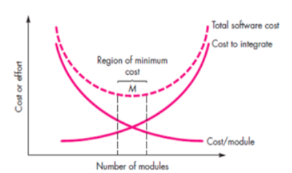
Fig 14: modularity
Q15) Write about Information Hiding, functional dependence and refinement?
A51) Information Hiding
The theory of hiding information implies that modules are "Characterized by design decisions that hide from everyone else." In other words, modules should be defined and configured so that information stored within a module (algorithms and data) is inaccessible to other modules that do not require such information.
Hiding means that it is possible to achieve successful modularity by specifying a series of independent modules that interact with each other only with the information required to achieve software functionality.
Abstraction helps describe the groups that make up the software that are procedural (or informational). Hiding defines and enforces access restrictions within a module and any local data structure used by the module for both procedural information.
Functional Independence
The idea of functional independence is a direct outgrowth of Separation of interests, modularity, and the principles of hiding knowledge and abstraction.
The creation of modules with "single minded" features and an "aversion" to undue contact with other modules achieves functional independence. In other words, you can design software such that each module addresses a particular subset of requirements and, when viewed from other sections of the programme structure, has a simple interface.
Two qualitative measures are used to determine independence: cohesion and coupling.
A single task is carried out by a cohesive module, requiring little contact with other modules in other parts of a programme. Simply put, a coherent module can do only one thing (ideally).
Although you should always aim for high cohesion (i.e. single-mindedness), making a software component perform several functions is also important and advisable.
In a software structure, coupling is an indication of interconnection between modules. Coupling relies on the complexity of the interface between modules, the point at which a module entry or reference is made, and what data moves through the interface.
Refinement
Stepwise refinement is a technique for top-down design. The creation of a software is by successively refining procedural information levels. A hierarchy is defined by stepwise decomposing a macroscopic function statement (a procedural abstraction) until programming language statements are reached.
In reality, refinement is a process of elaboration that starts with a function statement (or knowledge description) that is described at a high level of abstraction. As design advances, sophistication allows you to uncover low-level information.
Q16) Define Aspects, refactoring, Object-Oriented Design Concept and Design Classes?
A16) Aspects
A collection of "concerns" is discovered as the review of requirements occurs. These “Include requirements, use cases, features, data structures, quality of service problems, variants, boundaries of intellectual property, collaborations, trends and contracts".
Ideally, a model of requirements should be designed in a way that allows you to separate each problem (requirement) so that it can be independently considered. However, in fact, some of these problems span the entire structure and cannot be easily compartmentalized.
Refactoring
For several agile processes, a significant design task is the refactoring of a Technique of reorganization that simplifies a component's design (or code) without modifying its purpose or behaviour. "Refactoring is the process of modifying a software system in such a way that it does not change the code [design]’s behaviour, but improves its internal structure."
The current design is checked for duplication, unused design components, ineffective or redundant algorithms, improperly designed or inadequate data structures, or some other design flaw that can be changed to create a better design when software is refactored. The effect would be software that is easier to integrate, easier to evaluate, and easier to manage.
Object-Oriented Design Concept
In modern software engineering, the object-oriented (OO) paradigm is commonly used. Concepts of OO architecture, such as classes and artefacts, inheritance, Messages, and, among others, polymorphism.
Design Classes
You can identify a collection of design classes as the design model evolves,
By providing design specifics that will allow the classes to be implemented, and implementing a software infrastructure that supports the business solution, they refine the study classes. It is possible to create five different categories of design classes, each representing a different layer of design architecture.
User interface classes - All abstractions that are required for human computer interaction are specified by user interface classes (HCI).HCI exists in certain instances within the context of a metaphor (e.g. a cheque book, an order form, a fax machine), and the interface design classes can be visual representations of the metaphor components.
Business domain classes - Sometimes, business domain classes are refinements of the classes of study. The classes specify the attributes and services (methods) needed to implement a certain business domain component.
Process classes - Lower-level business abstractions needed to handle the business domain classes completely are implemented by process classes.
Persistent classes - Persistent classes describe stores of data (e.g. a database) that will survive after the programme execution.
System classes - System classes incorporate programme management and control functions that allow the system to run and interact with the outside world and within its computing environment.
They describe four features of a well-formed class of design:
● Complete and sufficient
● Primitiveness
● High cohesion
● Low coupling
Q17) Write the difference between coupling and cohesion?
A17) Difference between coupling and cohesion
Cohesion | Coupling |
Intra module cohesion is a concept. | Inter module coupling is a principle. |
The relationship within a module is described by cohesion. | The relationship between modules is represented by coupling. |
Software benefits from increased cohesion. | For applications, increasing coupling is avoided. |
The functional strength of modules is described by cohesion. | The independence of modules is represented by coupling. |
Software that is highly cohesive is the strongest. | Loose coupling, on the other hand, produces the best applications. |
Modules concentrate on a particular thing in cohesion. | Modules are bound to one another in coupling. |


