Unit - 2
Physical Layer
Q1) What is the basic principle applied to arrive at seven layers?
A1) The OSI model is shown in Fig. This model is based on a proposal developed by the International Standards Organization (ISO) as a first step toward international standardization of the protocols used in the various layers (Day and Zimmermann, 1983). It was revised in 1995. The model is called the ISO-OSI (Open Systems Interconnection) Reference Model because it deals with connecting open systems—that is, systems that are open for communication with other systems. The OSI model has seven layers. The principles that were applied to arrive at the seven layers can be briefly summarized as follows:
1. A layer should be created where a different abstraction is needed.
2. Each layer should perform a well-defined function.
3. The function of each layer should be chosen with an eye toward defining internationally standardized protocols.
4. The layer boundaries should be chosen to minimize the information flow across the interfaces.
5. The number of layers should be large enough that distinct functions need not be thrown together in the same layer out of necessity and small enough that the architecture does not become unwieldy.

Fig: OSI Reference Model
Q2) Explain the layers of OSI model?
A2) The Physical Layer: The physical layer is concerned with transmitting raw bits over a communication channel. The design issues have to do with making sure that when one side sends a 1 bit, it is received by the other side as a 1 bit, not as a 0 bit.
The Data Link Layer: The main task of the data link layer is to transform a raw transmission facility into a line that appears free of undetected transmission errors to the network layer. It accomplishes this task by having the sender break up the input data into data frames (typically a few hundred or a few thousand bytes) and transmits the frames sequentially. If the service is reliable, the receiver confirms correct receipt of each frame by sending back an acknowledgement frame. Another issue that arises in the data link layer (and most of the higher layers as well) is how to keep a fast transmitter from drowning a slow receiver in data. Some traffic regulation mechanism is often needed to let the transmitter know how much buffer space the receiver has at the moment. Frequently, this flow regulation and the error handling are integrated.
The Network Layer: The network layer controls the operation of the subnet. A key design issue is determining how packets are routed from source to destination. Routes can be based on static tables that are ''wired into'' the network and rarely changed. They can also be determined at the start of each conversation, for example, a terminal session (e.g., a login to a remote machine).
Finally, they can be highly dynamic, being determined anew for each packet, to reflect the current network load. If too many packets are present in the subnet at the same time, they will get in one another's way, forming bottlenecks. The control of such congestion also belongs to the network layer. More generally, the quality of service provided (delay, transit time, jitter, etc.) is also a network layer issue. When a packet has to travel from one network to another to get to its destination, many problems can arise.
The addressing used by the second network may be different from the first one. The second one may not accept the packet at all because it is too large. The protocols may differ, and so on. It is up to the network layer to overcome all these problems to allow heterogeneous networks to be interconnected. In broadcast networks, the routing problem is simple, so the network layer is often thin or even nonexistent.
The Transport Layer: The basic function of the transport layer is to accept data from above, split it up into smaller units if need be, pass these to the network layer, and ensure that the pieces all arrive correctly at the other end. Furthermore, all this must be done efficiently and in a way that isolates the upper layers from the inevitable changes in the hardware technology. The transport layer also determines what type of service to provide to the session layer, and, ultimately, to the users of the network. The most popular type of transport connection is an error-free point-to-point channel that delivers messages or bytes in the order in which they were sent.
However, other possible kinds of transport service are the transporting of isolated messages, with no guarantee about the order of delivery, and the broadcasting of messages to multiple destinations. The type of service is determined when the connection is established. The transport layer is a true end-to-end layer, all the way from the source to the destination. In other words, a program on the source machine carries on a conversation with a similar program on the destination machine, using the message headers and control messages. In the lower layers, the protocols are between each machine and its immediate neighbours, and not between the ultimate source and destination machines, which may be separated by many routers.
The Session Layer: The session layer allows users on different machines to establish sessions between them. Sessions offer various services, including dialog control (keeping track of whose turn it is to transmit), token management (preventing two parties from attempting the same critical operation at the same time), and synchronization (check pointing long transmissions to allow them to continue from where they were after a crash).
The Presentation Layer: The presentation layer is concerned with the syntax and semantics of the information transmitted. In order to make it possible for computers with different data representations to communicate, the data structures to be exchanged can be defined in an abstract way, along with a standard encoding to be used ''on the wire.'' The presentation layer manages these abstract data structures and allows higher-level data structures (e.g., banking records), to be defined and exchanged.
The Application Layer: The application layer contains a variety of protocols that are commonly needed by users. One widely-used application protocol is HTTP (Hypertext Transfer Protocol), which is the basis for the World Wide Web. When a browser wants a Web page, it sends the name of the page it wants to the server using HTTP. The server then sends the page back. Other application protocols are used for file transfer, electronic mail, and network news.
Q3) Explain the guided Media of transmission?
A3) Guided Media
It is defined as the physical medium through which the signals are transmitted. It is also known as Bounded media.
Types of Guided media:
Twisted pair:
Twisted pair is a physical media made up of a pair of cables twisted with each other. A twisted pair cable is cheap as compared to other transmission media. Installation of the twisted pair cable is easy, and it is a lightweight cable. The frequency range for twisted pair cable is from 0 to 3.5 KHz.
A twisted pair consists of two insulated copper wires arranged in a regular spiral pattern.
The degree of reduction in noise interference is determined by the number of turns per foot. Increasing the number of turns per foot decreases noise interference.

Types of Twisted pair:
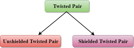
Unshielded Twisted Pair:
An unshielded twisted pair is widely used in telecommunication. Following are the categories of the unshielded twisted pair cable:
- Category 1: Category 1 is used for telephone lines that have low-speed data.
- Category 2: It can support upto 4Mbps.
- Category 3: It can support upto 16Mbps.
- Category 4: It can support upto 20Mbps. Therefore, it can be used for long-distance communication.
- Category 5: It can support upto 200Mbps.
Advantages of Unshielded Twisted Pair:
- It is cheap.
- Installation of the unshielded twisted pair is easy.
- It can be used for high-speed LAN.
Disadvantage:
- This cable can only be used for shorter distances because of attenuation.
Shielded Twisted Pair
A shielded twisted pair is a cable that contains the mesh surrounding the wire that allows the higher transmission rate.
Characteristics of Shielded Twisted Pair:
- The cost of the shielded twisted pair cable is not very high and not very low.
- An installation of STP is easy.
- It has higher capacity as compared to unshielded twisted pair cable.
- It has a higher attenuation.
- It is shielded that provides the higher data transmission rate.
Disadvantages
- It is more expensive as compared to UTP and coaxial cable.
- It has a higher attenuation rate.
Coaxial Cable
- Coaxial cable is very commonly used transmission media, for example, TV wire is usually a coaxial cable.
- The name of the cable is coaxial as it contains two conductors parallel to each other.
- It has a higher frequency as compared to Twisted pair cable.
- The inner conductor of the coaxial cable is made up of copper, and the outer conductor is made up of copper mesh. The middle core is made up of non-conductive cover that separates the inner conductor from the outer conductor.
- The middle core is responsible for the data transferring whereas the copper mesh prevents from the EMI(Electromagnetic interference).

Coaxial cable is of two types:
- Baseband transmission: It is defined as the process of transmitting a single signal at high speed.
- Broadband transmission: It is defined as the process of transmitting multiple signals simultaneously.
Advantages of Coaxial cable:
- The data can be transmitted at high speed.
- It has better shielding as compared to twisted pair cable.
- It provides higher bandwidth.
Disadvantages of Coaxial cable:
- It is more expensive as compared to twisted pair cable.
- If any fault occurs in the cable causes the failure in the entire network.
Fibre Optic
- Fibre optic cable is a cable that uses electrical signals for communication.
- Fibre optic is a cable that holds the optical fibres coated in plastic that are used to send the data by pulses of light.
- The plastic coating protects the optical fibres from heat, cold, electromagnetic interference from other types of wiring.
- Fibre optics provides faster data transmission than copper wires.
Diagrammatic representation of fibre optic cable:

Basic elements of Fibre optic cable:
- Core: The optical fibre consists of a narrow strand of glass or plastic known as a core. A core is a light transmission area of the fibre. The more the area of the core, the lighter will be transmitted into the fibre.
- Cladding: The concentric layer of glass is known as cladding. The main functionality of the cladding is to provide the lower refractive index at the core interface as to cause the reflection within the core so that the light waves are transmitted through the fibre.
- Jacket: The protective coating consisting of plastic is known as a jacket. The main purpose of a jacket is to preserve the fibre strength, absorb shock and extra fibre protection.
Following are the advantages of fibre optic cable over copper:
- Greater Bandwidth: The fibre optic cable provides more bandwidth as compared copper. Therefore, the fibre optic carries more data as compared to copper cable.
- Faster speed: Fibre optic cable carries the data in the form of light. This allows the fibre optic cable to carry the signals at a higher speed.
- Longer distances: The fibre optic cable carries the data at a longer distance as compared to copper cable.
- Better reliability: The fibre optic cable is more reliable than the copper cable as it is immune to any temperature changes while it can cause obstruct in the connectivity of copper cable.
- Thinner and Sturdier: Fibre optic cable is thinner and lighter in weight so it can withstand more pull pressure than copper cable.
Q4) Explain the unguided transmission media?
A4) Unguided Transmission
- An unguided transmission transmits the electromagnetic waves without using any physical medium. Therefore it is also known as wireless transmission.
- In unguided media, air is the media through which the electromagnetic energy can flow easily.
Unguided transmission is broadly classified into three categories:
Radio waves
- Radio waves are the electromagnetic waves that are transmitted in all the directions of free space.
- Radio waves are omnidirectional, i.e., the signals are propagated in all the directions.
- The range in frequencies of radio waves is from 3Khz to 1 khz.
- In the case of radio waves, the sending and receiving antenna are not aligned, i.e., the wave sent by the sending antenna can be received by any receiving antenna.
- An example of the radio wave is FM radio.
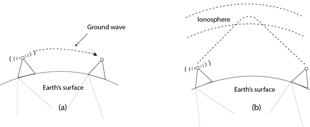
Applications of Radio waves:
- A Radio wave is useful for multicasting when there is one sender and many receivers.
- An FM radio, television, cordless phones are examples of a radio wave.
Advantages of Radio transmission:
- Radio transmission is mainly used for wide area networks and mobile cellular phones.
- Radio waves cover a large area, and they can penetrate the walls.
- Radio transmission provides a higher transmission rate.
Microwaves
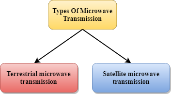
Microwaves are of two types:
- Terrestrial microwave
- Satellite microwave communication.
Terrestrial Microwave Transmission
- Terrestrial Microwave transmission is a technology that transmits the focused beam of a radio signal from one ground-based microwave transmission antenna to another.
- Microwaves are the electromagnetic waves having the frequency in the range from 1GHz to 1000 GHz.
- Microwaves are unidirectional as the sending and receiving antenna is to be aligned, i.e., the waves sent by the sending antenna are narrowly focussed.
- In this case, antennas are mounted on the towers to send a beam to another antenna which is km away.
- It works on the line of sight transmission, i.e., the antennas mounted on the towers are the direct sight of each other.
Characteristics of Microwave:
- Frequency range: The frequency range of terrestrial microwave is from 4-6 GHz to 21-23 GHz.
- Bandwidth: It supports the bandwidth from 1 to 10 Mbps.
- Short distance: It is inexpensive for short distance.
- Long distance: It is expensive as it requires a higher tower for a longer distance.
- Attenuation: Attenuation means loss of signal. It is affected by environmental conditions and antenna size.
Advantages of Microwave:
- Microwave transmission is cheaper than using cables.
- It is free from land acquisition as it does not require any land for the installation of cables.
- Microwave transmission provides an easy communication in terrains as the installation of cable in terrain is quite a difficult task.
- Communication over oceans can be achieved by using microwave transmission.
Disadvantages of Microwave transmission:
- Eavesdropping: An eavesdropping creates insecure communication. Any malicious user can catch the signal in the air by using its own antenna.
- Out of phase signal: A signal can be moved out of phase by using microwave transmission.
- Susceptible to weather condition: A microwave transmission is susceptible to weather condition. This means that any environmental change such as rain, wind can distort the signal.
- Bandwidth limited: Allocation of bandwidth is limited in the case of microwave transmission.
Satellite Microwave Communication
- A satellite is a physical object that revolves around the earth at a known height.
- Satellite communication is more reliable nowadays as it offers more flexibility than cable and fibre optic systems.
- We can communicate with any point on the globe by using satellite communication.
How Does Satellite work?
The satellite accepts the signal that is transmitted from the earth station, and it amplifies the signal. The amplified signal is retransmitted to another earth station.
Advantages of Satellite Microwave Communication:
- The coverage area of a satellite microwave is more than the terrestrial microwave.
- The transmission cost of the satellite is independent of the distance from the centre of the coverage area.
- Satellite communication is used in mobile and wireless communication applications.
- It is easy to install.
- It is used in a wide variety of applications such as weather forecasting, radio/TV signal broadcasting, mobile communication, etc.
Disadvantages of Satellite Microwave Communication:
- Satellite designing and development requires more time and higher cost.
- The Satellite needs to be monitored and controlled on regular periods so that it remains in orbit.
- The life of the satellite is about 12-15 years. Due to this reason, another launch of the satellite has to be planned before it becomes non-functional.
Infrared
- An infrared transmission is a wireless technology used for communication over short ranges.
- The frequency of the infrared in the range from 300 GHz to 400 THz.
- It is used for short-range communication such as data transfer between two cell phones, TV remote operation, data transfer between a computer and cell phone resides in the same closed area.
Characteristics of Infrared:
- It supports high bandwidth, and hence the data rate will be very high.
- Infrared waves cannot penetrate the walls. Therefore, the infrared communication in one room cannot be interrupted by the nearby rooms.
- An infrared communication provides better security with minimum interference.
- Infrared communication is unreliable outside the building because the sun rays will interfere with the infrared waves.
Q5) Explain the Bus and Ring network topology?
A5) Topology refers to the network's structure and how all of the elements are linked to one another. Physical and logical topology are the two forms of topology.
The geometric representation of all the nodes in a network is known as physical topology.
● Bus topology: The bus topology is set up in such a way that all of the stations are linked together by a single backbone cable. Each node is either connected to the backbone cable through a drop cable or is directly connected to it.
When a node wishes to send a message across the network, it does so by sending a message across the network. Regardless of whether the message has been answered, it will be received by all available stations in the network.
The bus topology is commonly used in regular networks such as 802.3 (ethernet) and 802.4 (wireless). In comparison to other topologies, the configuration of a bus topology is very straightforward. The backbone cable is thought of as a "single path" from which the message is sent to all of the stations.
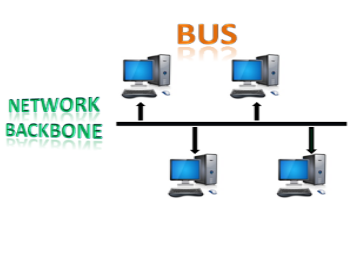
Fig: Bus topology
● Ring topology: The topology of a ring is similar to that of a bus, but with connected ends. The node that receives the previous computer's message will retransmit to the next node. The data is unidirectional, meaning it only moves in one direction.
The data is continually flowed in a single loop, which is referred to as an infinite loop. It has no terminated ends, which means that each node is connected to the next and has no point of termination.
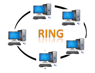
Fig: Ring topology
Q6) Explain star and tree topology?
A6)
● Star topology: The star topology is a network configuration in which each node is connected to a central hub, switch, or device. The central computer is referred to as a server, and the peripheral devices connected to it as clients.
The computers are connected via coaxial cable or RJ-45 cables. In a physical star topology, hubs or switches are primarily used as connection devices. The star topology is the most widely used network topology.
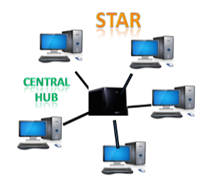
Fig: Star topology
● Tree topology: Tree topology incorporates the advantages of both bus and star topologies. A tree topology is a system in which all computers are related to one another in a hierarchical manner.
A root node is the top-most node in a tree topology, and all other nodes are descendants of the root node. For data transmission, there is only one path between two nodes. As a result, it creates a parent-child hierarchy.
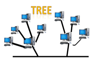
Fig: Tree topology
Q7) Explain hybrid and mesh topology?
A7)
● Mesh topology: Mesh technology is a network configuration in which computers are connected to one another through multiple redundant connections. There are many ways to get from one device to another. It is devoid of the turn, hub, or any central device that serves as a communication hub.
The mesh topology is exemplified by the Internet. Mesh topology is most commonly used in WAN deployments where communication failures are a major concern. Wireless networks commonly use the mesh topology.
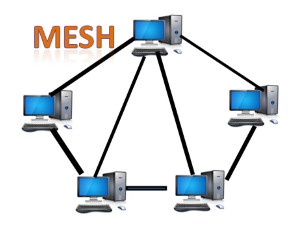
Fig: Mesh topology
● Hybrid topology: Hybrid topology is the synthesis of many different topologies. A hybrid topology connects various links and nodes in order to transfer data. Hybrid topology is described as the combination of two or more different topologies, while similar topologies connecting to each other do not result in Hybrid topology.
For example, if a ring topology exists in one SBI bank branch and a bus topology exists in another SBI bank branch, connecting these two topologies would result in a Hybrid topology.
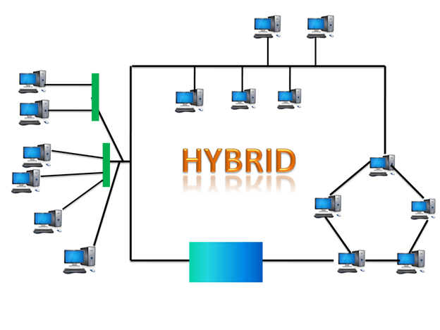
Fig: Hybrid topology
Q8) Explain the types of data link protocol?
A8) Types of Data Link Protocols
Data link protocols can be broadly divided into two categories, depending on whether the transmission channel is noiseless or noisy.
- Simplex Protocol
The Simplex protocol is hypothetical protocol designed for unidirectional data transmission over an ideal channel, i.e. a channel through which transmission can never go wrong. It has distinct procedures for sender and receiver. The sender simply sends all its data available onto the channel as soon as they are available its buffer. The receiver is assumed to process all incoming data instantly. It is hypothetical since it does not handle flow control or error control.
b. Stop – and – Wait Protocol
Stop – and – Wait protocol is for noiseless channel too. It provides unidirectional data transmission without any error control facilities. However, it provides for flow control so that a fast sender does not drown a slow receiver. The receiver has a finite buffer size with finite processing speed. The sender can send a frame only when it has received indication from the receiver that it is available for further data processing.
c. Stop – and – Wait ARQ
Stop-and– wait Automatic Repeat Request (Stop – and – Wait ARQ) is a variation of the above protocol with added error control mechanisms, appropriate for noisy channels. The sender keeps a copy of the sent frame. It then waits for a finite time to receive a positive acknowledgement from receiver. If the timer expires or a negative acknowledgement is received, the frame is retransmitted. If a positive acknowledgement is received, then the next frame is sent.
d. Go – Back – N ARQ
Go – Back – N ARQ provides for sending multiple frames before receiving the acknowledgement for the first frame. It uses the concept of sliding window, and so is also called sliding window protocol. The frames are sequentially numbered and a finite number of frames are sent. If the acknowledgement of a frame is not received within the time period, all frames starting from that frame are retransmitted.
e. Selective Repeat ARQ
This protocol also provides for sending multiple frames before receiving the acknowledgement for the first frame. However, here only the erroneous or lost frames are retransmitted, while the good frames are received and buffered.
f. Sliding window protocols
The sliding window is a technique for sending multiple frames at a time. It controls the data packets between the two devices where reliable and gradual delivery of data frames is needed. It is also used in TCP (Transmission Control Protocol).
In this technique, each frame has sent from the sequence number. The sequence numbers are used to find the missing data in the receiver end. The purpose of the sliding window technique is to avoid duplicate data, so it uses the sequence number.
Q9) What are the types of sliding window protocol. Explain them all?
A9) Types of Sliding Window Protocol
Sliding window protocol has two types:
Go-Back-N ARQ
Selective Repeat ARQ
Go-Back-N ARQ
Go-Back-N ARQ protocol is also known as Go-Back-N Automatic Repeat Request. It is a data link layer protocol that uses a sliding window method. In this, if any frame is corrupted or lost, all subsequent frames have to be sent again. The size of the sender window is N in this protocol. For example, Go-Back-8, the size of the sender window, will be 8. The receiver window size is always 1. If the receiver receives a corrupted frame, it cancels it. The receiver does not accept a corrupted frame. When the timer expires, the sender sends the correct frame again.
Selective Repeat ARQ
Selective Repeat ARQ is also known as the Selective Repeat Automatic Repeat Request. It is a data link layer protocol that uses a sliding window method. The Go-Back-N ARQ protocol works well if it has fewer errors. But if there is a lot of error in the frame, lots of bandwidth loss in sending the frames again. So, we use the Selective Repeat ARQ protocol. In this protocol, the size of the sender window is always equal to the size of the receiver window. The size of the sliding window is always greater than 1.
If the receiver receives a corrupt frame, it does not directly discard it. It sends a negative acknowledgment to the sender. The sender sends that frame again as soon as on the receiving negative acknowledgment. There is no waiting for any time-out to send that frame.
Q10) What is the condition called when the receiver’s information does not match with sender’s information?
A10) Error handling
A condition when the receiver’s information does not match with the sender’s information. During transmission, digital signals suffer from noise that can introduce errors in the binary bits travelling from sender to receiver. That means a 0 bit may change to 1 or a 1 bit may change to 0.
Whenever a message is transmitted, it may get scrambled by noise or data may get corrupted. To avoid this, we use error-detecting codes which are additional data added to a given digital message to help us detect if any error has occurred during transmission of the message.
Basic approach used for error detection is the use of redundancy bits, where additional bits are added to facilitate detection of errors.
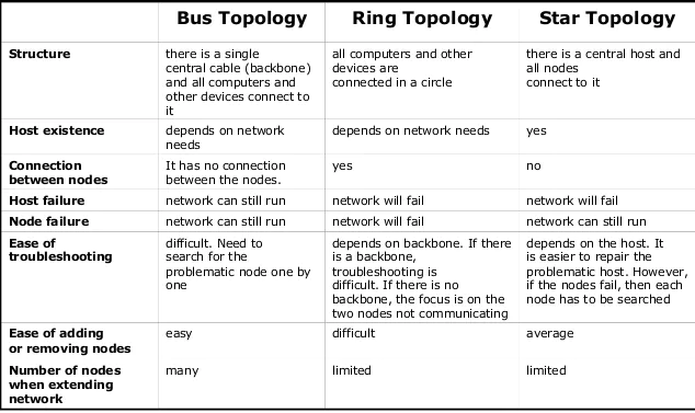
Q11) Explain the difference between network topologies?
A11)
Q12) Explain any two techniques for error detection?
A12) Basic approach used for error detection is the use of redundancy bits, where additional bits are added to facilitate detection of errors.
1. Simple Parity check
Blocks of data from the source are subjected to a check bit or parity bit generator form, where a parity of:
1 is added to the block if it contains odd number of 1’s, and
0 is added if it contains even number of 1’s
This scheme makes the total number of 1’s even, that is why it is called even parity checking.
2. Two-dimensional Parity check
Parity check bits are calculated for each row, which is equivalent to a simple parity check bit. Parity check bits are also calculated for all columns, then both are sent along with the data. At the receiving end these are compared with the parity bits calculated on the received data.
Q13) what is CRC?
A13) Cyclic Redundancy Check (CRC)
CRC is a redundancy error technique used to determine the error.
Following are the steps used in CRC for error detection:
- In CRC technique, a string of n 0s is appended to the data unit, and this n number is less than the number of bits in a predetermined number, known as division which is n+1 bits.
- Secondly, the newly extended data is divided by a divisor using a process is known as binary division. The remainder generated from this division is known as CRC remainder.
- Thirdly, the CRC remainder replaces the appended 0s at the end of the original data. This newly generated unit is sent to the receiver.
- The receiver receives the data followed by the CRC remainder. The receiver will treat this whole unit as a single unit, and it is divided by the same divisor that was used to find the CRC remainder.
If the resultant of this division is zero which means that it has no error, and the data is accepted.
If the resultant of this division is not zero which means that the data consists of an error. Therefore, the data is discarded.
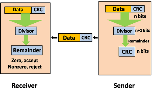
Fig – Data CRC
Let's understand this concept through an example:
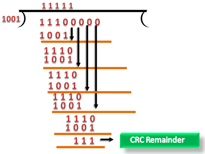
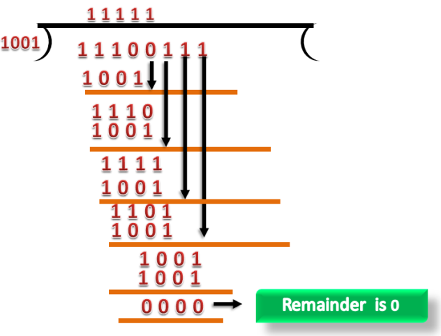
Suppose the original data is 11100 and divisor is 1001.
CRC Generator
- A CRC generator uses a modulo-2 division. Firstly, three zeroes are appended at the end of the data as the length of the divisor is 4 and we know that the length of the string 0s to be appended is always one less than the length of the divisor.
- Now, the string becomes 11100000, and the resultant string is divided by the divisor 1001.
- The remainder generated from the binary division is known as CRC remainder. The generated value of the CRC remainder is 111.
- CRC remainder replaces the appended string of 0s at the end of the data unit, and the final string would be 11100111 which is sent across the network.
CRC Checker
- The functionality of the CRC checker is similar to the CRC generator.
- When the string 11100111 is received at the receiving end, then CRC checker performs the modulo-2 division.
- A string is divided by the same divisor, i.e., 1001.
- In this case, CRC checker generates the remainder of zero. Therefore, the data is accepted.
Q14) Explain the 2D parity checker?
A14) Two-Dimensional Parity Check
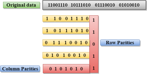
- Performance can be improved by using Two-Dimensional Parity Check which organizes the data in the form of a table.
- Parity check bits are computed for each row, which is equivalent to the single-parity check.
- In Two-Dimensional Parity check, a block of bits is divided into rows, and the redundant row of bits is added to the whole block.
- At the receiving end, the parity bits are compared with the parity bits computed from the received data.
Drawbacks Of 2D Parity Check
- If two bits in one data unit are corrupted and two bits exactly the same position in another data unit are also corrupted, then 2D Parity checker will not be able to detect the error.
- This technique cannot be used to detect the 4-bit errors or more in some cases.
Q15) What is stop and wait protocol?
A15) Here stop and wait means, whatever the data that sender wants to send, he sends the data to the receiver. After sending the data, he stops and waits until he receives the acknowledgment from the receiver. The stop and wait protocol is a flow control protocol where flow control is one of the services of the data link layer.
It is a data-link layer protocol which is used for transmitting the data over the noiseless channels. It provides unidirectional data transmission which means that either sending or receiving of data will take place at a time. It provides flow-control mechanism but does not provide any error control mechanism.
The idea behind the usage of this frame is that when the sender sends the frame then he waits for the acknowledgment before sending the next frame.
Primitives of Stop and Wait Protocol
The primitives of stop and wait protocol are:
Sender side
Rule 1: Sender sends one data packet at a time.
Rule 2: Sender sends the next packet only when it receives the acknowledgment of the previous packet.
Therefore, the idea of stop and wait protocol in the sender's side is very simple, i.e., send one packet at a time, and do not send another packet before receiving the acknowledgment.
Receiver side
Rule 1: Receive and then consume the data packet.
Rule 2: When the data packet is consumed, receiver sends the acknowledgment to the sender.
Therefore, the idea of stop and wait protocol in the receiver's side is also very simple, i.e., consume the packet, and once the packet is consumed, the acknowledgment is sent. This is known as a flow control mechanism.
Working of Stop and Wait protocol
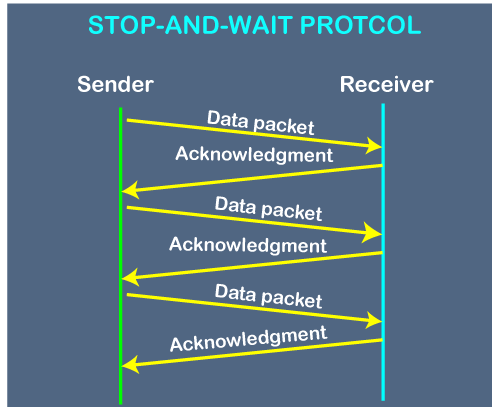
Fig - Working of Stop and Wait protocol
The above figure shows the working of the stop and wait protocol. If there is a sender and receiver, then sender sends the packet and that packet is known as a data packet. The sender will not send the second packet without receiving the acknowledgment of the first packet. The receiver sends the acknowledgment for the data packet that it has received. Once the acknowledgment is received, the sender sends the next packet. This process continues until all the packet are not sent. The main advantage of this protocol is its simplicity but it has some disadvantages also. For example, if there are 1000 data packets to be sent, then all the 1000 packets cannot be sent at a time as in Stop and Wait protocol, one packet is sent at a time.
Q16) Explain the problems associated with the stop and wait protocol?
A16) The following are the problems associated with a stop and wait protocol:
1. Problems occur due to lost data
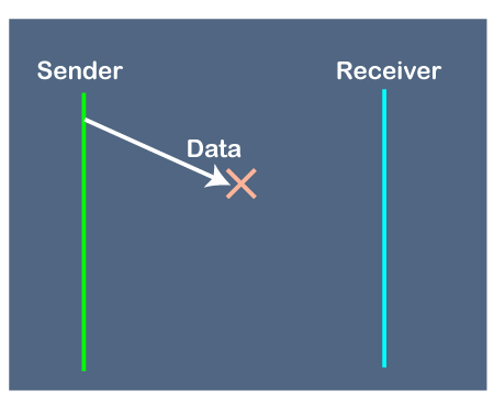
Fig - Problems occur due to lost data
Suppose the sender sends the data and the data is lost. The receiver is waiting for the data for a long time. Since the data is not received by the receiver, so it does not send any acknowledgment. Since the sender does not receive any acknowledgment so it will not send the next packet. This problem occurs due to the lost data.
In this case, two problems occur:
- Sender waits for an infinite amount of time for an acknowledgment.
- Receiver waits for an infinite amount of time for a data.
2. Problems occur due to lost acknowledgment
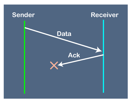
Suppose the sender sends the data and it has also been received by the receiver. On receiving the packet, the receiver sends the acknowledgment. In this case, the acknowledgment is lost in a network, so there is no chance for the sender to receive the acknowledgment. There is also no chance for the sender to send the next packet as in stop and wait protocol, the next packet cannot be sent until the acknowledgment of the previous packet is received.
In this case, one problem occurs:
- Sender waits for an infinite amount of time for an acknowledgment.
3. Problem due to the delayed data or acknowledgment
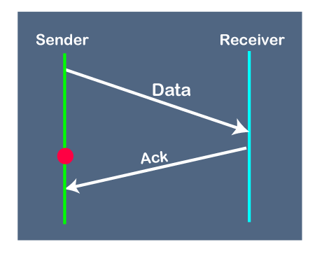
Suppose the sender sends the data and it has also been received by the receiver. The receiver then sends the acknowledgment but the acknowledgment is received after the timeout period on the sender's side. As the acknowledgment is received late, so acknowledgment can be wrongly considered as the acknowledgment of some other data packet.
Q17) In GB4, if every 6th packet being transmitted is lost and if we have to spend 10 packets then how many transmissions are required?
A17) Here, GB4 means that N is equal to 4. The size of the sender's window is 4.
Step 1: As the window size is 4, so four packets are transferred at a time, i.e., packet no 1, packet no 2, packet no 3, and packet no 4.
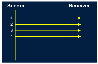
Step 2: Once the transfer of window size is completed, the sender receives the acknowledgment of the first frame, i.e., packet no1. As the acknowledgment receives, the sender sends the next packet, i.e., packet no 5. In this case, the window slides having four packets, i.e., 2,3,4,5 and excluded the packet 1 as the acknowledgment of the packet 1 has been received successfully.
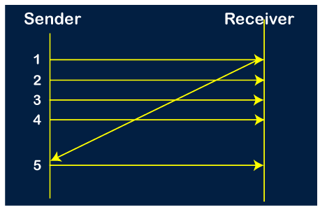
Step 3: Now, the sender receives the acknowledgment of packet 2. After receiving the acknowledgment for packet 2, the sender sends the next packet, i.e., packet no 6. As mentioned in the question that every 6th is being lost, so this 6th packet is lost, but the sender does not know that the 6th packet has been lost.
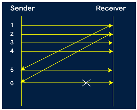
Step 4: The sender receives the acknowledgment for the packet no 3. After receiving the acknowledgment of 3rd packet, the sender sends the next packet, i.e., 7th packet. The window will slide having four packets, i.e., 4, 5, 6, 7.
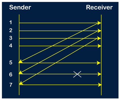
Step 5: When the packet 7 has been sent, then the sender receives the acknowledgment for the packet no 4. When the sender has received the acknowledgment, then the sender sends the next packet, i.e., the 8th packet. The window will slide having four packets, i.e., 5, 6, 7, 8.
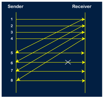
Step 6: When the packet 8 is sent, then the sender receives the acknowledgment of packet 5. On receiving the acknowledgment of packet 5, the sender sends the next packet, i.e., 9th packet. The window will slide having four packets, i.e., 6, 7, 8, 9.
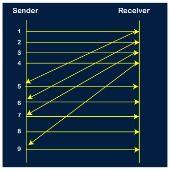
Step 7: The current window is holding four packets, i.e., 6, 7, 8, 9, where the 6th packet is the first packet in the window. As we know, the 6th packet has been lost, so the sender receives the negative acknowledgment NAK(6). As we know that every 6th packet is being lost, so the counter will be restarted from 1. So, the counter values 1, 2, 3 are given to the 7th packet, 8th packet, 9th packet respectively.
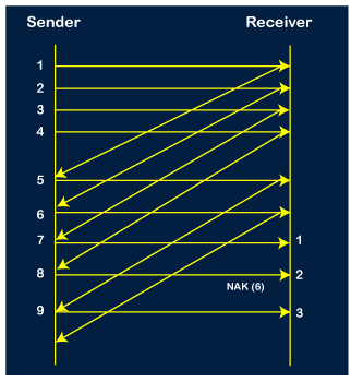
Step 8: As it is Go-BACK, so it retransmits all the packets of the current window. It will resend 6, 7, 8, 9. The counter values of 6, 7, 8, 9 are 4, 5, 6, 1, respectively. In this case, the 8th packet is lost as it has a 6-counter value, so the counter variable will again be restarted from 1.
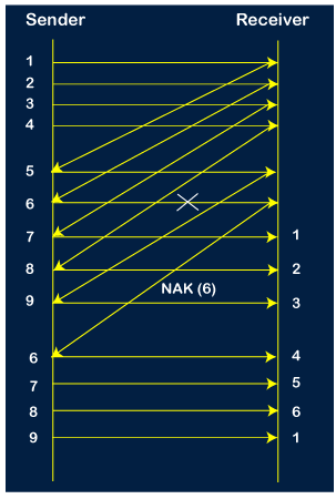
Step 9: After the retransmission, the sender receives the acknowledgment of packet 6. On receiving the acknowledgment of packet 6, the sender sends the 10th packet. Now, the current window is holding four packets, i.e., 7, 8, 9, 10.
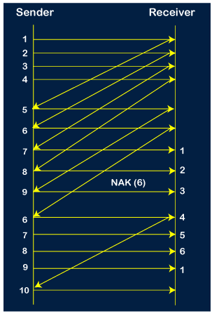
Step 10: When the 10th packet is sent, the sender receives the acknowledgment of packet 7. Now the current window is holding three packets, 8, 9 and 10. The counter values of 8, 9, 10 are 6, 1, 2.
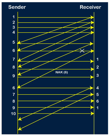
Step 11: As the 8th packet has 6 counter value which means that 8th packet has been lost, and the sender receives NAK (8).
Step 12: Since the sender has received the negative acknowledgment for the 8th packet, it resends all the packets of the current window, i.e., 8, 9, 10.
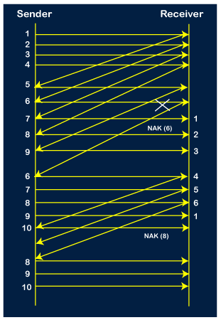
Step 13: The counter values of 8, 9, 10 are 3, 4, 5, respectively, so their acknowledgments have been received successfully.
We conclude from the above figure that total 17 transmissions are required.
Q18) Explain the difference between Go Back N ARQ and Selective Repeat ARQ?
A18)
Go-Back-N ARQ | Selective Repeat ARQ |
If a frame is corrupted or lost in it, all subsequent frames have to be sent again. | In this, only the frame is sent again, which is corrupted or lost. |
If it has a high error rate, it wastes a lot of bandwidth. | There is a loss of low bandwidth. |
It is less complex. | It is more complex because it has to do sorting and searching as well. And it also requires more storage. |
It does not require sorting. | In this, sorting is done to get the frames in the correct order. |
It does not require searching. | The search operation is performed in it. |
It is used more. | It is used less because it is more complex. |
Q19) Write the comparison between a switch and a hub?
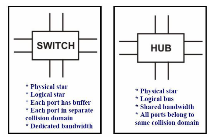
A19) Comparison between a switch and a hub Although a hub and a switch apparently look similar, they have significant differences. As shown in Figure, both can be used to realize physical star topology, the hubs work like a logical bus, because the same signal is repeated on all the ports. On the other hand, a switch functions like a logical star with the possibility of the communication of separate signals between any pair of port lines. As a consequence, all the ports of a hub belong to the same collision domain, and in case of a switch each port operates on separate collision domain. Moreover, in case of a hub, the bandwidth is shared by all the stations connected to all the ports. On the other hand, in case of a switch, each port has dedicated bandwidth. Therefore, switches can be used to increase the bandwidth of a hub-based network by replacing the hubs by switches.
Q20) What is framing and explain its types?
A20)
- Framing is a point-to-point connection between two computers or devices which consists of a wire in which data is transmitted as a stream of bits.
- However, these bits must be framed into discernible blocks of information.
- Framing is the function of the data link layer. It provides a way for a sender to transmit a set of bits that are meaningful to the receiver.
- Ethernet, token ring, frame relay, and other data link layer technologies have their own frame structures.
- Frames have headers that contain information such as error-checking codes.
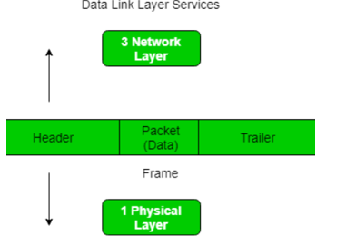
At data link layer it extracts message from sender and provide it to the receiver by providing sender’s and receiver’s address.
The advantage of using frames is that data is broken up into recoverable chunks that can easily be checked for corruption.
Types of framing – There are two types of framing:
1. Fixed size – The frame is of fixed size and there is no need to provide boundaries to the frame, length of the frame itself acts as delimiter.
2. Variable size – In this there is need to define end of frame as well as beginning of next frame to distinguish.
This can be done in two ways:
- Length field – We can introduce a length field in the frame to indicate the length of the frame. Used in Ethernet(802.3).
- End Delimeter (ED) – We can introduce an ED(pattern) to indicate the end of the frame. Used in Token Ring.