Unit 3
Direct broadcast satellite television and radio
Q1) How a C/A code is generated?
Sol: The figure shows the C/A code generator. The C/A code is of which satellite is identified by its identification number. The C/A code for a satellite with ID i will be
Ci(t) = G1(t) x G2(t+10iTc)
G1 and G2 are the 1023 bits m-sequence two gold codes.
Tc = clock period for C/A code
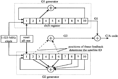
Fig: C/A Code Generator
A correlator that is in the receiver selects only one sequence and rejects all others. If two C/A codes have zero cross-correlation then they will be rejected. The entire C/A code sequence repeats in space every 300km. This results in uncertainty in the position of the GPS receiver.
Q2) Explain non-coherent detection in the time domain?
Sol: In serial search, the simplest algorithms are used and are easy to implement. The digital input x[n] is multiplied with the replicated C/A codes. When these codes are removed then the in-phase component I and the quadrature component Q undergo for one more period N and then this sum is squared. After this k correlations are accumulated to produce an average correlation point. The block diagram is shown below.

Fig: Non-coherent correlator in the time domain
Q3) Explain the FFT search scheme with an algorithm?
Sol: In FFT Search replica codes are correlated with the samples of received data by circular shifting the replica codes. The circular convolution is multiplication in the frequency domain this is an advantage for this scheme.
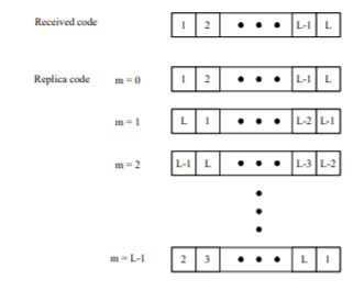
Fig: Algorithm

Fig: Block diagram for FFT search
The DFT is calculated by the real and imaginary components which are in-phase and the quadrature component of the received signal. The circular convolution is obtained by taking the magnitude of inverse DFT. The FFT algorithm is used to implement DFT and IDFT.
Q4) How P-codes and C/A are used in GPS navigation?
Sol: The navigation message contains a large amount of information that is used by the GPS receiver to optimize the acquisition of satellite signals and calculate position. At 50 bps the navigation message is sent using BPSK modulation of C/A and P codes. One navigation bit message is formed by 20 C/A code sequences. There is a high S/N ratio at demodulator and low probability of bit error in navigation message due to the narrow bandwidth of navigation message.
For extracting navigation messages, a 50-bps BPSK demodulator is used which is followed by C/A or P-code correlators. A 1500 bits navigation message is sent with 30 frames having 5 subframes. The elements which are important in the message are repeated in every frame. The clock time data, orbital ephemeris of the satellite is contained by subframes.
GPS Navigation Message
Header | Telemetry message |
Subframe 1 | Satellite clock correction data |
Subframe 2 and 3 | Ephemeris of satellite |
Subframe 4 | Ionospheric model data for satellite 25 and higher |
Subframe 5 | Health data for satellite 1-24 |
The above table shows the explanation and the information on the subframes we discussed above.
Q5) What are GPS signal levels?
Sol: Due to the use of omnidirectional antennas, the GPS receiver has low gain. Usually, the GPS antennas are circularly polarised. To avoid an increase in noise temperature due to lossy antenna cables low noise amplifiers are used (LNA). The low C/N ratio of the spread spectrum is converted to a useful S/N ratio by correlation of code sequence.
The signal from 10 satellites at a time can be picked by the GPS receiver. The interference is added in the receiver because of RF energy from the satellite spread spectrum. The cross-correlation of noise with the wanted signal is zero.
At 50 bps the navigation message is sent using BPSK modulation of C/A and P codes. One navigation bit message is formed by 20 C/A code sequences. For extracting navigation messages, a 50-bps BPSK demodulator is used which is followed by C/A or P-code correlators. A 1500 bits navigation message is sent with 30 frames having 5 subframes.
The S/N ratio of the BPSK signal theoretically is 13dB higher than the S/N ratio of correlator output. As the implementation of correlation and filtering is not perfect so a margin of a few dB is allowed.
Q6) Why the accuracy of the GPS is better when the C/N ratio is high?
Sol: At the receiver end the arrival of the code sequence should be on the accurate measurement of time. A pulse of 1 microsecond at the output of the correlator repeats itself after every millisecond. The accuracy of timing measurement for the pulse can be given by
 t =
t = 
 t = rms timing value
Bn = noise bandwidth of the RF channel
The S/N ratio after the correlator is given by
S/N = C/N + Gp – losses
Gp = correlator processing gain.
For C/A codes Gp = 1023=30.1dB
S/N = -19.3+ 30.1-losses
= 11.7-losses
The higher the C/N ratio in the receiver better will be the accuracy.
Q7) Draw the block diagram and explain GPS receiver operation?
Sol: The block diagram of the GPS receiver is shown below. The user only needs a GPS receiver because it is only one-way from the satellite for transmission to the users. The receiver tracks the exact location of the object.

Fig: Block Diagram of GPS Receiver
A circular polarised antenna is used at the receiving end and the low noise amplifiers are used (function is discussed in the previous section). The frequency of the received signal is converted to an intermediate frequency level by IF amplifiers. The output from the IF amplifier is converted to digital using ADC converters. The C/A code is generated by the digital signal processor. The calculation of position and the timing signal is done by the microprocessor which then displays the output.
Q8) Explain global positioning systems?
Sol: The global positioning satellite system has upgraded navigation and position for aircraft, ships, and majorly in surveying. The GPS satellite transmits L- band signals. There are many codes used in the transmission of the signal. Initially coarse acquisition code (C/A) was made public and later P codes were used. The P codes were very helpful in military uses. The GPS systems are widely used as they provide the exact location of the GPS receiver.
The GPS satellite transmits two signals of frequencies L1 and L2. The L2 signals are modulated with 10.23 Mbps pseudorandom codes (PN) known as P-code. The P codes are used in military positioning systems.
The GPS consists of a clock that is synchronized with each clock on the receiving satellite. GPS provides two categories of service. The precise positioning service (PPS) and standard positioning service (SPS). In PPS receivers track P codes and C/A codes and are used in the military. The SPS receiver track C/A codes, this service is used by the general public.
Q9) What are DBS-TV?
Sol: The satellite broadcast of television is a major part of satellite communication. In 1999 the DSB-TV and video distribution were the major part of satellite communication. With technology now these DSB-TV and video distribution have become digital. They have a small antenna and the receiving system has a very low cost. The 20-Msps QPSK signal is used in digital DBS-TV signals transmission. The 40-Mbps signal has a data rate of 23-27 Mbps with remaining bits for error control and system operations.
Many error correction and detection techniques are used in DBS-TV digital signals. The detected errors which remain after decoding of digital signal result in single word errors. The development of DBS-TV satellites with spot beam for local news broadcast has provided the higher satellite antenna gain needed for uplink from 0.5 m dishes.
Both DirectTV and Dishnetwork offer an internet access terminal with uplink capability. The satellite radio broadcast emerged in 2000 from three Sirius satellites in elliptical orbits and two XM satellites in GEO. The signals are transmitted in the S-band at 2.3GHz and are focused mainly in automobiles where the users are highest. To overcome signal blockage repeaters are used in cities.
Q10) Derive the ranging equations for the three satellite location positions?
Sol: The prerequisite requirement for a GPS system is that there must be four satellites transmitting a coded signal from known positions. The position location in GPS is done by defining the coordinates for GPS receiver and GPS satellite. A rectangular coordinate system is defined as having a centre of the earth as its origin.
The axes are directed as Z-axis in North pole, Y-axis through 900 east meridian, and X-axis through-line of zero. The distance measured to the satellite is denoted by I and is called a pseudo-range.

Fig: Position Location of three satellites
The pseudo-range can be measured as
PR = Ti x c
Ti = propagation time delay
C = velocity of EM wave.
Each satellite sends ephemeris data signal along with timing signals. The receiver calculates the coordinates satellite relative to centre of the earth. The distance R is given as
R2 = (xA-xB)2 + (yA-yB)2 +(zA-zB)2
The ranging equations are given as
(X1-Ux)2 + (Y1-Uy)2 + (Z1-Uz)2 = (PR1 - c)2
c)2
(X2-Ux)2 + (Y2-Uy)2 + (Z2-Uz)2 = (PR2 - c)2
c)2
(X3-Ux)2 + (Y3-Uy)2 + (Z3-Uz)2 = (PR3 - c)2
c)2
(X4-Ux)2 + (Y4-Uy)2 + (Z4-Uz)2 = (PR4 - c)2
c)2
 = receiver clock error
The value of  can be added to the GPS receiver so that time measurement is synchronized to standard GPS time. All GPS receivers are automatically in sync with any other GPS satellite anywhere in the world.
Unit 3
Direct broadcast satellite television and radio
Q1) How a C/A code is generated?
Sol: The figure shows the C/A code generator. The C/A code is of which satellite is identified by its identification number. The C/A code for a satellite with ID i will be
Ci(t) = G1(t) x G2(t+10iTc)
G1 and G2 are the 1023 bits m-sequence two gold codes.
Tc = clock period for C/A code
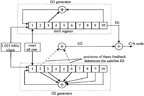
Fig: C/A Code Generator
A correlator that is in the receiver selects only one sequence and rejects all others. If two C/A codes have zero cross-correlation then they will be rejected. The entire C/A code sequence repeats in space every 300km. This results in uncertainty in the position of the GPS receiver.
Q2) Explain non-coherent detection in the time domain?
Sol: In serial search, the simplest algorithms are used and are easy to implement. The digital input x[n] is multiplied with the replicated C/A codes. When these codes are removed then the in-phase component I and the quadrature component Q undergo for one more period N and then this sum is squared. After this k correlations are accumulated to produce an average correlation point. The block diagram is shown below.

Fig: Non-coherent correlator in the time domain
Q3) Explain the FFT search scheme with an algorithm?
Sol: In FFT Search replica codes are correlated with the samples of received data by circular shifting the replica codes. The circular convolution is multiplication in the frequency domain this is an advantage for this scheme.
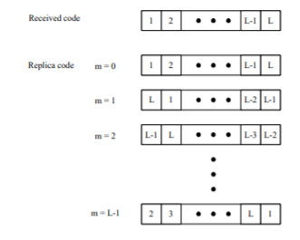
Fig: Algorithm

Fig: Block diagram for FFT search
The DFT is calculated by the real and imaginary components which are in-phase and the quadrature component of the received signal. The circular convolution is obtained by taking the magnitude of inverse DFT. The FFT algorithm is used to implement DFT and IDFT.
Q4) How P-codes and C/A are used in GPS navigation?
Sol: The navigation message contains a large amount of information that is used by the GPS receiver to optimize the acquisition of satellite signals and calculate position. At 50 bps the navigation message is sent using BPSK modulation of C/A and P codes. One navigation bit message is formed by 20 C/A code sequences. There is a high S/N ratio at demodulator and low probability of bit error in navigation message due to the narrow bandwidth of navigation message.
For extracting navigation messages, a 50-bps BPSK demodulator is used which is followed by C/A or P-code correlators. A 1500 bits navigation message is sent with 30 frames having 5 subframes. The elements which are important in the message are repeated in every frame. The clock time data, orbital ephemeris of the satellite is contained by subframes.
GPS Navigation Message
Header | Telemetry message |
Subframe 1 | Satellite clock correction data |
Subframe 2 and 3 | Ephemeris of satellite |
Subframe 4 | Ionospheric model data for satellite 25 and higher |
Subframe 5 | Health data for satellite 1-24 |
The above table shows the explanation and the information on the subframes we discussed above.
Q5) What are GPS signal levels?
Sol: Due to the use of omnidirectional antennas, the GPS receiver has low gain. Usually, the GPS antennas are circularly polarised. To avoid an increase in noise temperature due to lossy antenna cables low noise amplifiers are used (LNA). The low C/N ratio of the spread spectrum is converted to a useful S/N ratio by correlation of code sequence.
The signal from 10 satellites at a time can be picked by the GPS receiver. The interference is added in the receiver because of RF energy from the satellite spread spectrum. The cross-correlation of noise with the wanted signal is zero.
At 50 bps the navigation message is sent using BPSK modulation of C/A and P codes. One navigation bit message is formed by 20 C/A code sequences. For extracting navigation messages, a 50-bps BPSK demodulator is used which is followed by C/A or P-code correlators. A 1500 bits navigation message is sent with 30 frames having 5 subframes.
The S/N ratio of the BPSK signal theoretically is 13dB higher than the S/N ratio of correlator output. As the implementation of correlation and filtering is not perfect so a margin of a few dB is allowed.
Q6) Why the accuracy of the GPS is better when the C/N ratio is high?
Sol: At the receiver end the arrival of the code sequence should be on the accurate measurement of time. A pulse of 1 microsecond at the output of the correlator repeats itself after every millisecond. The accuracy of timing measurement for the pulse can be given by
 t =
t = 
 t = rms timing value
Bn = noise bandwidth of the RF channel
The S/N ratio after the correlator is given by
S/N = C/N + Gp – losses
Gp = correlator processing gain.
For C/A codes Gp = 1023=30.1dB
S/N = -19.3+ 30.1-losses
= 11.7-losses
The higher the C/N ratio in the receiver better will be the accuracy.
Q7) Draw the block diagram and explain GPS receiver operation?
Sol: The block diagram of the GPS receiver is shown below. The user only needs a GPS receiver because it is only one-way from the satellite for transmission to the users. The receiver tracks the exact location of the object.

Fig: Block Diagram of GPS Receiver
A circular polarised antenna is used at the receiving end and the low noise amplifiers are used (function is discussed in the previous section). The frequency of the received signal is converted to an intermediate frequency level by IF amplifiers. The output from the IF amplifier is converted to digital using ADC converters. The C/A code is generated by the digital signal processor. The calculation of position and the timing signal is done by the microprocessor which then displays the output.
Q8) Explain global positioning systems?
Sol: The global positioning satellite system has upgraded navigation and position for aircraft, ships, and majorly in surveying. The GPS satellite transmits L- band signals. There are many codes used in the transmission of the signal. Initially coarse acquisition code (C/A) was made public and later P codes were used. The P codes were very helpful in military uses. The GPS systems are widely used as they provide the exact location of the GPS receiver.
The GPS satellite transmits two signals of frequencies L1 and L2. The L2 signals are modulated with 10.23 Mbps pseudorandom codes (PN) known as P-code. The P codes are used in military positioning systems.
The GPS consists of a clock that is synchronized with each clock on the receiving satellite. GPS provides two categories of service. The precise positioning service (PPS) and standard positioning service (SPS). In PPS receivers track P codes and C/A codes and are used in the military. The SPS receiver track C/A codes, this service is used by the general public.
Q9) What are DBS-TV?
Sol: The satellite broadcast of television is a major part of satellite communication. In 1999 the DSB-TV and video distribution were the major part of satellite communication. With technology now these DSB-TV and video distribution have become digital. They have a small antenna and the receiving system has a very low cost. The 20-Msps QPSK signal is used in digital DBS-TV signals transmission. The 40-Mbps signal has a data rate of 23-27 Mbps with remaining bits for error control and system operations.
Many error correction and detection techniques are used in DBS-TV digital signals. The detected errors which remain after decoding of digital signal result in single word errors. The development of DBS-TV satellites with spot beam for local news broadcast has provided the higher satellite antenna gain needed for uplink from 0.5 m dishes.
Both DirectTV and Dishnetwork offer an internet access terminal with uplink capability. The satellite radio broadcast emerged in 2000 from three Sirius satellites in elliptical orbits and two XM satellites in GEO. The signals are transmitted in the S-band at 2.3GHz and are focused mainly in automobiles where the users are highest. To overcome signal blockage repeaters are used in cities.
Q10) Derive the ranging equations for the three satellite location positions?
Sol: The prerequisite requirement for a GPS system is that there must be four satellites transmitting a coded signal from known positions. The position location in GPS is done by defining the coordinates for GPS receiver and GPS satellite. A rectangular coordinate system is defined as having a centre of the earth as its origin.
The axes are directed as Z-axis in North pole, Y-axis through 900 east meridian, and X-axis through-line of zero. The distance measured to the satellite is denoted by I and is called a pseudo-range.
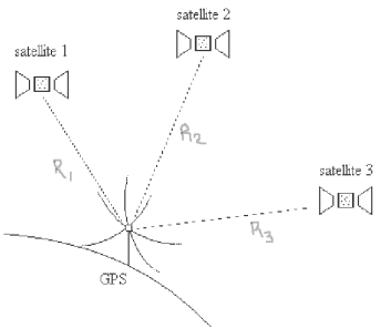
Fig: Position Location of three satellites
The pseudo-range can be measured as
PR = Ti x c
Ti = propagation time delay
C = velocity of EM wave.
Each satellite sends ephemeris data signal along with timing signals. The receiver calculates the coordinates satellite relative to centre of the earth. The distance R is given as
R2 = (xA-xB)2 + (yA-yB)2 +(zA-zB)2
The ranging equations are given as
(X1-Ux)2 + (Y1-Uy)2 + (Z1-Uz)2 = (PR1 - c)2
c)2
(X2-Ux)2 + (Y2-Uy)2 + (Z2-Uz)2 = (PR2 - c)2
c)2
(X3-Ux)2 + (Y3-Uy)2 + (Z3-Uz)2 = (PR3 - c)2
c)2
(X4-Ux)2 + (Y4-Uy)2 + (Z4-Uz)2 = (PR4 - c)2
c)2
 = receiver clock error
The value of  can be added to the GPS receiver so that time measurement is synchronized to standard GPS time. All GPS receivers are automatically in sync with any other GPS satellite anywhere in the world.