Unit – 1
Node and mesh analysis
Q1) Find the current flowing through 20 Ω resistor of the following circuit using Nodal analysis.

A1)
Step 1 − There are three principle nodes in the above circuit. Those are labelled as 1, 2, and 3 in the following figure. In the above figure, consider node 3 as reference node (Ground).

Step 2 − The node voltages, V1 and V2, are labelled in the following figure.

Step 3 – There are two nodal equations, since there are two principal nodes, 1 and 2, other than Ground.
The nodal equation at node 1 is
V1 -20/5 + V1/10 + V1-V2/10 =0
2V1 -40 +V1+V1-V2/10 =0
4V1 -40-V2 =0 --- V2 = 4V1-40 -------(1)
The nodal equation at node 2 is
-4 +V2/20 + V2-V1/10 =0
-80 + V2 + 2 V2 – 2V2/ 20 =0
= 3V2 -2V1 =80 --------------(2)
Step 4 − Finding node voltages, V1 and V2 by solving Equation 1 and Equation 2.
Substitute Equation 1 in Equation 2.
3(4V1−40)−2V1=80
⇒12V1−120−2V1=80
⇒10V1=200
⇒V1=20V
Substitute V1 = 20 V in Equation1.
V2=4(20)−40
⇒V2=40V
So, we got the node voltages V1 and V2 as 20 V and 40 V respectively.
Step 5 − The voltage across 20 Ω resistor is nothing but the node voltage V2 and it is equal to 40 V. Now, we can find the current flowing through 20 Ω resistor by using Ohm’s law.
I 20Ω = V2/R
Substitute the values of V2 and R
I 20 Ω = 40/20
I 20Ω = 2A
Therefore, the current flowing through the 20Ω resistor is 2A.
Q2) Find the voltage across 30 Ω resistor using Mesh analysis.

A2)
Step 1 − There are two meshes in the above circuit. The mesh currents I1 and I2 are considered in clockwise direction. These mesh currents are shown in the following figure.

Step 2 − The mesh current I1 flows through 20 V voltage source and 5 Ω resistor. Similarly, the mesh current I2 flows through 30 Ω resistor and -80 V voltage source. But, the difference of two mesh currents, I1 and I2, flows through 10 Ω resistor, since it is the common branch of two meshes.
Step 3 − Since there are two meshes in the given circuit write the mesh equations, assume the mesh current of that particular mesh as greater than all other mesh currents of the circuit.
The mesh equation of first mesh is
20−5I1−10(I1−I2)=0
⇒20−15I1+10I2=0
⇒10I2=15I1−20
Divide the above equation with 5.
2I2=3I1−4
Multiply the above equation with 2.
4I2=6I1−8-----------------(1)
The mesh equation of second mesh is
−10(I2−I1)−30 I2+80=0
Divide the above equation with 10.
−(I2−I1)−3I2+8=0
⇒−4I2+I1+8=0-----------------(2)
4I2 = I1 +8
Step 4 − Finding mesh currents I1 and I2 by solving Equation 1 and Equation 2.
The left-hand side terms of Equation 1 and Equation 2 are the same. Hence, equate the right-hand side terms of Equation 1 and Equation 2 in order find the value of I1.
6I1 -8 = I1 +8
5I1 =16
I1 = 16/5 A
Hence, 4I2 = 16/5 + 8
4I2 = 56/5
I2 = 56/20 = 2.8 A
Step 5 − The current flowing through 30 Ω resistor is nothing but the mesh current I2 and it is equal to 14/5 A. The voltage across 30 Ω resistor by using Ohm’s law.
V 30 Ω = I2 R
V30Ω = (14/5) x 30 = 84V
Q3) Solve the circuit using Mesh matrix analysis. Work from first principles.

A3) Let us first number the branches and the loops.

Let us write the loop currents in terms of the branch currents.
i1 = I1
i2 = - I3
i3 = I1 – I2
i4 = I2
i5 = I2 – I3
i6 = I3
Or in matrix form we can write it as
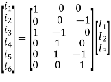
This gives us the [B] matrix or the Branch-Mesh incidence matrix. We can also write the Mesh–Branch incidence matrix [B]t matrix as follows, independent of the above, by writing the relation between the mesh direction and the branch direction.

The vector of branch currents Egb can be written as follows.

We now need to write the branch impedance matrix. Then we can write expressions for the mesh voltage vector and the mesh impedance matrix using the derived equations.
Egm = [B]t Egb , and [Zm] = [B]t [Zb] [B]
The Branch impedance matrix is 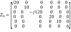
Thus we can write the mesh source voltage vector

This could also have been written by inspection by writing down the sources effectively driving the mesh currents round the loops. If first principles is not asked for, writing by inspection would generally be sufficient. The mesh impedance matrix can be written as

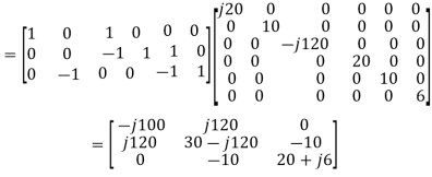
This matrix too could have been written by inspection, and would normally have been done that way, if first principles were not required. Thus, we may now write the mesh analysis equation as

The equations may be solved by inversion or otherwise.
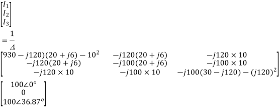

The discriminant ∆ is given by


Thus, I1 is given as


Currents I2 and I3 can be similarly determined. The branch currents i1, i2, ..... May then be determined from the matrix equation. May then be determined from the matrix equation.
Q4) Solve the circuit using Mesh matrix analysis. Work from first principles.

A4) Let us first convert the above circuit with current sources. The network may also be drawn in terms of admittances as follows.
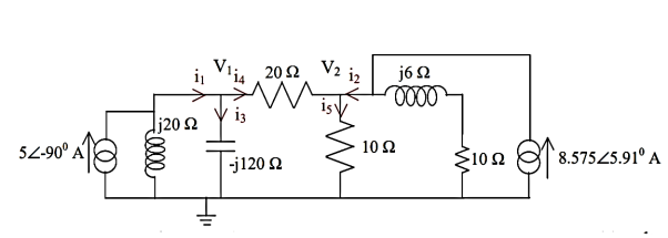
The branch-node incidence matrix [A], branch injected current Igb, and the branch admittance matrix may be written, with the reference selected as the earthed node as


As in the case of mesh analysis, the nodal current injection vector and the nodal admittance matrix may be written from first principles.


The branch current will be


Q5) Find the output voltage using source transformation technique. For the given circuit?
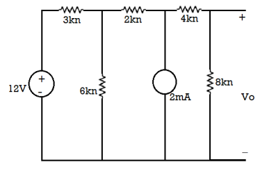
A5) The 12 V Voltage source transfers into Current source:
I =12/3 =4 mA
After source transformation the circuit will be
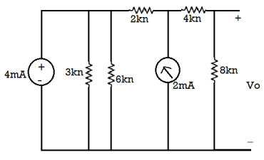
The 3KΩ and 6 KΩ are parallel to each other so equivalent resistance = (3x6)/(3+6) = 2k
The equivalent circuit will now be
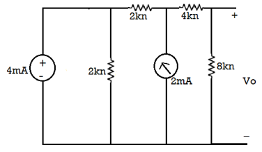
The 4mA current source transfers voltage of =4x2 =8V
The reduced circuit diagram is
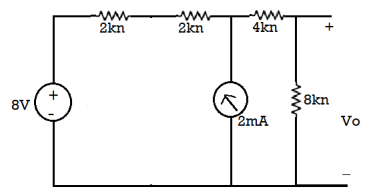
Now 2k and 2k are in series
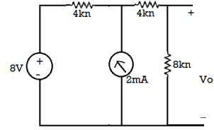
The 8V voltage source convert into current source: = 8/4 = 2A
The circuit diagram is
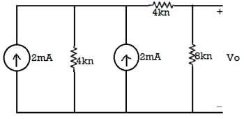
The both current source are in same direction so add the both current sources.
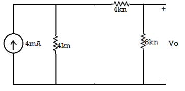
The 4mA current source transfer into a voltage source: = 4 × 4 = 16 V
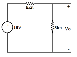
So, calculate the output voltage across 8 ohm using voltage divider rule:
𝑉0 = 16 × 8/(8 + 8) = 8 V
Q6) Draw the dual of the network shown in figure
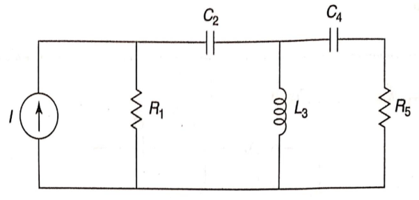
A6) For drawing the dual network, mark the node and dashed lines
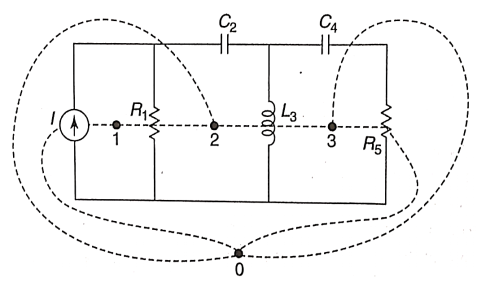
The dual network is shown in figure
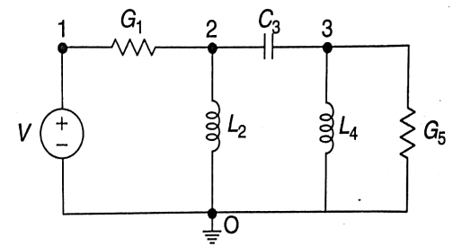
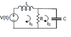
Q7) For the circuits given below write the voltage equations:
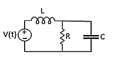
A7) Let current i1be in loop 1 current and i2 for loop 2


Q8) Write the loop equations for the given circuit below?
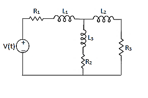
A8)
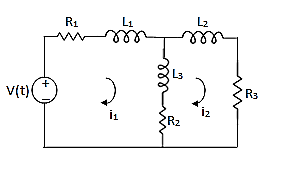
For loop 1

For loop 2

Q9) Using nodal analysis find voltage across 5 ohm resistor.
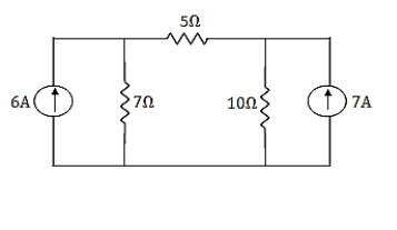
A9)
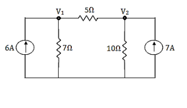
For V1


For V2


Solving 1 and 2:


For 5 voltage = 
= -50.9 + 57.27
= 6.37V
Q10) Find the node voltage in the network shown in figure.
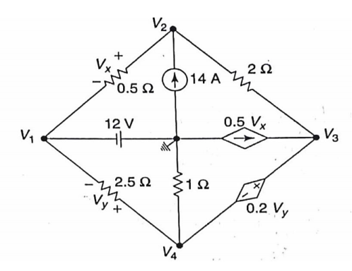
A10) The node voltage V1 is

Applying KCL at node 2,


Nodes 3 and 4 will form a super node. The voltage equation for the super node.


Solving above equation for given node voltages we get
V1 = -12V
V2 = -4V
V3 = 0
V4 = -2V
Q11) For the circuit shown in figure, Find the voltage across 4Ω resistor by using nodal analysis.
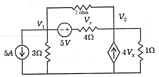
A11) Let the voltage at node 1 and 2 be V1 and V2.
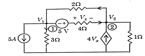

Now applying KCL at node 1


Applying KCL at node 2 we get


Solving


Again we have the following set of equations


Again we have


The value Vx will be

Q12) Draw the dual of the network shown in figure
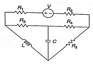
A12) For drawing the dual network, mark the node and dashed lines
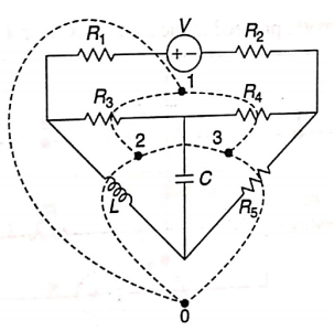
The dual network is shown in figure
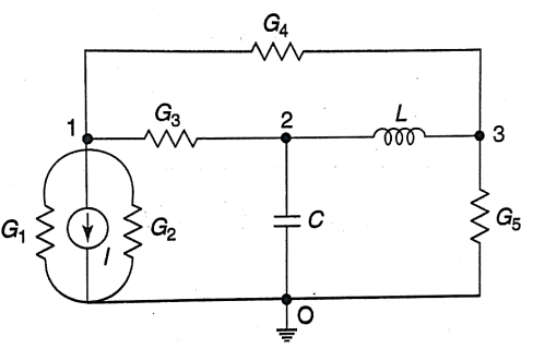
Q13) Find dual for the series RLC circuit?
A13) Let us consider RLC circuit
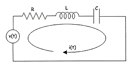
Fig RLC Circuit
Applying KVL we have
v(t) = ri(t) + L  +
+ 
So, dual of above network will be
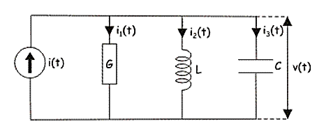
Fig Dual of RLC circuit
i(t) = Gv(t) + C  +
+ 
Q14) For the characteristics given below comment about the type of element?
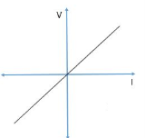
A14) It is Linear, Bilateral and Passive element
Q15) For the figure below comment on the type of element?
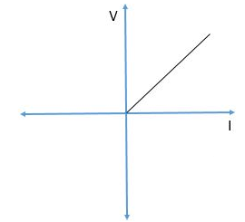
A15) The element is Non-Linear, Passive and Unilateral.