Unit 3
Oscillators
- Explain the concept of oscillators?
Sol:
An oscillator is a circuit that produces a continuous, repeated, alternating waveform without any input. Oscillators convert unidirectional current flow from a DC source into an alternating waveform which is of the desired frequency, as decided by its circuit components.
The basic principle behind the working of oscillators can be understood by analyzing the behaviour of an LC tank circuit shown in Figure below, which employs an inductor L and a completely pre-charged capacitor C as its components.
Here the capacitor starts to discharge via the inductor, which results in the conversion of its electrical energy into the electromagnetic field, which can be stored in the inductor. Once the capacitor discharges completely, there will be no current flow in the circuit.
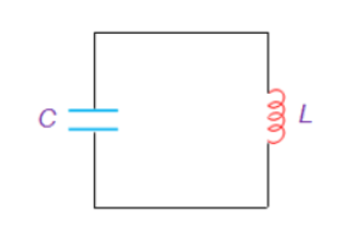
Figure. LC tank circuit
2. Explain the Barkhausen criterion?
Sol:
Conditions that are required to be satisfied to operate the circuit as an oscillator are called as “Barkhausen criterion” for sustained oscillations.
The Barkhausen criterion states that:
• The loop gain is equal to unity in absolute magnitude, that is, | β A | = 1 and
• The phase shift around the loop is zero or an integer multiple of 2π: ∠ β A = 2 π n, n ∈ 0, 1, 2,….
The product β A is called the “loop gain”.
3. Explain the advantage of the RC phase shift oscillator?
Sol:
In an RC Oscillator circuit, the input is shifted 180o through the feedback circuit returning the signal out-of-phase and 180o through an inverting amplifier stage to produces the required positive feedback.
This then gives us “180o + 180o = 360o” of phase shift which is effectively the same as 0o, thereby giving us the required positive feedback.
4. Explain the working of the RC phase shift oscillator?
Sol:
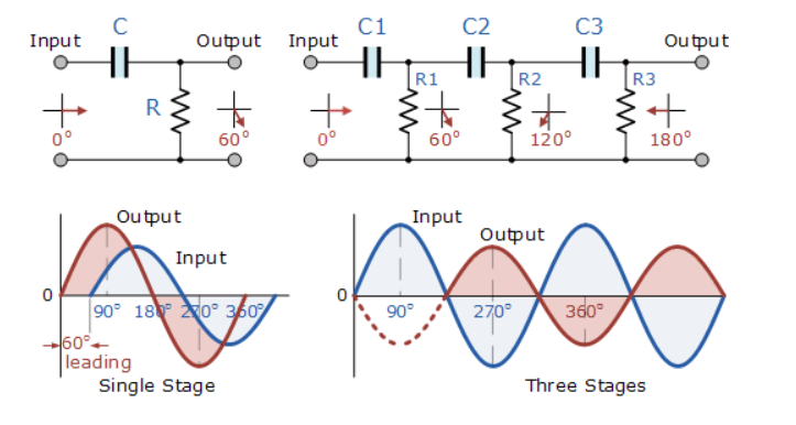
Figure 3. Single-stage and multi-stage phase shift oscillator
The circuit on the left shows a single resistor-capacitor network whose output voltage “leads” the input voltage by some angle less than 90o.
In a pure or ideal single-pole RC network. It would produce a maximum phase shift of exactly 90o, and because 180o of phase shift is required for oscillation, at least two single-poles networks must be used within an RC oscillator design.
However, in reality, it is difficult to obtain exactly 90o of phase shift for each RC stage so we must therefore use more RC stages cascaded together to obtain the required value at the oscillation frequency.
The amount of actual phase shift in the circuit depends upon the values of the resistor (R) and the capacitor (C), at the chosen frequency of oscillations with the phase angle ( φ ) being given as:
Xc = 1/2π fc R=R
Z = [ R 2 + Xc 2 ] ½
Ø = tan -1 Xc /R.
5. Explain the advantage of the Wein Bridge oscillator?
Sol:
Wien bridge oscillator is an audio frequency sine wave oscillator of high stability and simplicity. The feedback signal in this circuit is connected to the non-inverting input terminal so that the op-amp is working as a non-inverting amplifier.
The feedback network does not provide any phase shift. The circuit can be viewed as a Wien bridge with a series combination of R1 and C1 in one arm and a parallel combination of R2 and C2 in the adjoining arm. Resistors R3 and R4 are connected in the remaining two arms.
The condition of zero phase shift around the circuit is achieved by balancing the bridge. The series and parallel combination of RC networks form a lead-lag circuit.
6. Explain the working of the Wein bridge oscillator?
Sol:
At high frequencies, the reactance of capacitor C1 and C2 approaches zero. This causes C1 and C2 to appear short. Here, capacitor C2 shorts the resistor R2. Hence, the output voltage Vo will be zero since the output is taken across R2 and C2 combination. So, at high frequencies, the circuit acts as a 'lag circuit'.
At low frequencies, both capacitors act as open because the capacitor offers very high reactance. Again, the output voltage will be zero because the input signal is dropped across the R1 and C1 combination. Here, the circuit acts like a 'lead circuit'.
But at one particular frequency between the two extremes, the output voltage reaches the maximum value. At this frequency only, the resistance value becomes equal to capacitive reactance and gives maximum output. Hence, this frequency is known as the oscillating frequency (f).
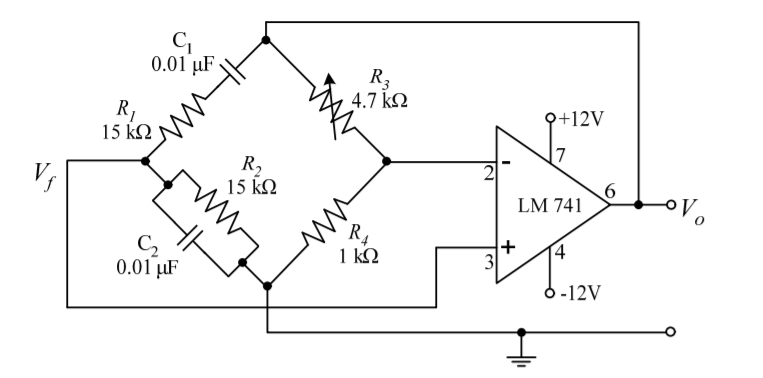
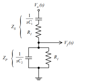
Figure 4. Wein bridge oscillator
Consider the feedback circuit, on applying voltage divider rule
Vf(s) = Vo(s) x Zp(s)/ Zp(s) + Zs(s)
Zs(s) = R1 + 1/sC1 and Zp(s) = R2|| 1/sC2
Let R1=R2=R and C1=C2=C.
On solving
β = Vf(s)/ Vo(s) = RsC /(RsC) 2 + 3RsC + 1 ---------------------------(1)
Since the op-amp is operated in the non-inverting configuration the voltage gain
Av = Vo(s)/ Vf(s) = 1 + R3/R4 -------------------(2)
Applying the condition for sustained oscillations, = Av β =1
RsC /(RsC) 2 + 3RsC + 1. 1 + R3/R4
S=jw
(1 + R3/R4) ( jwRC/ - R2 C2 w2 + 3 jwRC + 1) =1
Jw RC (1 + R3/R4)= (- R2 C2 w2 + 3 jwRC + 1)
Jw[(1 + R3/R4)RC – 3RC] = 1- R2 C2 w2
To obtain the frequency of oscillation equate the real part to zero
1- R2 C2 w2 = 0
w = 1/RC
f = 1/ 2 π RC
To obtain the condition for gain at the frequency of oscillation equate the imaginary part to zero.
Jw[(1 + R3/R4)RC – 3RC] = 0
jw[(1 + R3/R4)RC= jw3RC
[(1 + R3/R4) =3
R3/R4 =2
Therefore R3 = 2 R4 is the required condition.
7. Explain the working of the Hartley oscillator?
Sol:
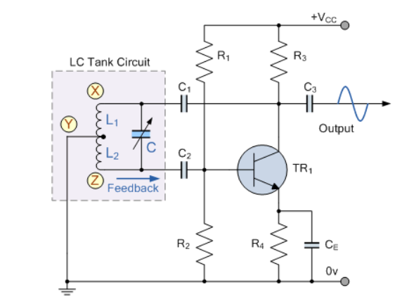
Figure 5. Hartley Oscillator
When the circuit is oscillating, the voltage at point X (collector), relative to point Y (emitter), is 180o out-of-phase with the voltage at point Z (base) relative to point Y.
At the frequency of oscillation, the impedance of the Collector load is resistive and an increase in Base voltage causes a decrease in the Collector voltage.
Thus, there is a 180o phase change in the voltage between the Base and Collector and this along with the original 180o phase shift in the feedback loop provides the correct phase relationship of positive feedback for oscillations to be maintained.
The amount of feedback depends upon the position of the “tapping point” of the inductor. If this is moved nearer to the collector the amount of feedback is increased, but the output taken between the Collector and earth is reduced and vice versa.
Resistors, R1 and R2 provide the usual stabilizing DC bias for the transistor in the normal manner while the capacitors act as DC-blocking capacitors.
In this Hartley Oscillator circuit, the DC Collector current flows through part of the coil, and for this reason the circuit is said to be “Series-fed” with the frequency of oscillation of the Hartley Oscillator being given as.
f=1/2π√ LTC
Where LT = L1 +L2 + 2M
8. Explain the working of Colpitts oscillator?
Sol:
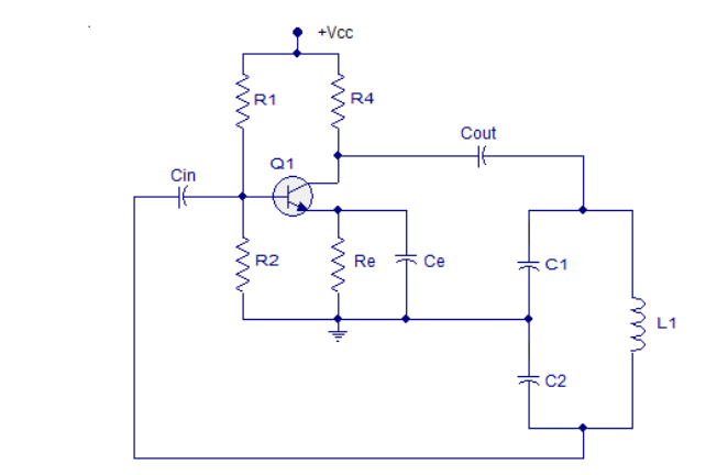
Figure 9. Colpitts oscillator
Resistors R1 and R2 work as voltage divider biasing to the transistor. Resistor R4 limits the collector current of the transistor.
Cin is the input DC decoupling capacitor while Cout is the output decoupling capacitor.
Re is the emitter resistor and it's meant for thermal stability. Ce is the emitter by-pass capacitor.
The job of the emitter by-pass capacitor is to by-pass the amplified AC signals from dropping across Re. The emitter by-pass capacitor is not there, the amplified AC signal will drop across Re and it will alter the DC biasing conditions of the transistor and the result will be reduced gain.
Capacitors C1, C2, and inductor L1 form the tank circuit. Feedback to the base of the transistor is taken from the junction of capacitor C2 and inductor L1 in the tank circuit.
When the power supply is switched ON, capacitors C1 and C2 starts charging. When they are fully charged they start discharging through the inductor L1. When the capacitors are fully discharged, the electrostatic energy stored in the capacitors gets transferred to the inductor as magnetic flux.
The inductor starts discharging and capacitors get charged again. This transfer of energy back and forth between capacitors and inductors is the basis of oscillation.
The voltage across C2 is phase opposite to that of the voltage across the C1 and it is the voltage across C2 that is fed back to the transistor. The feedback signal at the base of the transistor appears in the amplified form across the collector and emitter of the transistor.
The energy lost in the tank circuit is compensated by the transistor and the oscillations are sustained.
The tank circuit produces a 180° phase shift and the transistor itself produces another 180° phase shift. That means the input and output are in phase and it is a necessary condition of positive feedback for maintaining sustained oscillations.
The frequency of oscillations of the Colpitts oscillator can be determined using the equation below.
f = 1/ 2π√LC
Where L is the inductance of the inductor in the tank circuit and C is the effective capacitance of the capacitors in the tank circuit.
9. Determine the frequency of the oscillators in the figure. Assume there is negligible loading in the feedback circuit and Q >10.
Find the frequency of the oscillator is loaded to a point where Q drops to 8.
Sol:
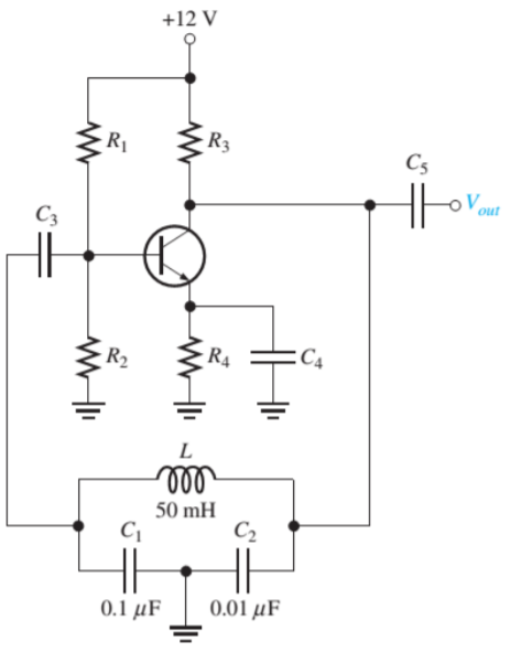
CT = C1C2/ C1 + C2 = (0.1 μF) (0.01μF) / 0.11 μF = 0.0091μF
Fr = 1/2π√LCT = 1/2π√(50mH)(0.0091μF) = 7.46kHz
Fr = 1/2π√LCT √ Q 2/ Q 2 + 1 = 7.46 x 0.9923 = 7.40 kHz
10. Explain non-sinusoidal oscillators?
Sol:
Oscillators that produce output that have square, rectangular, or sawtooth waveform or have an output which is of pulse shape are called Non- Sinusoidal Oscillators.
It is a circuit in which voltage or current changes abruptly from one value to another and which continues to oscillate between these two values as long as dc power is supplied to it.
These oscillators are classified as :
1. Sawtooth Generators
2. Blocking Oscillators
3. Multivibrators
Unit 3
Oscillators
- Explain the concept of oscillators?
Sol:
An oscillator is a circuit that produces a continuous, repeated, alternating waveform without any input. Oscillators convert unidirectional current flow from a DC source into an alternating waveform which is of the desired frequency, as decided by its circuit components.
The basic principle behind the working of oscillators can be understood by analyzing the behaviour of an LC tank circuit shown in Figure below, which employs an inductor L and a completely pre-charged capacitor C as its components.
Here the capacitor starts to discharge via the inductor, which results in the conversion of its electrical energy into the electromagnetic field, which can be stored in the inductor. Once the capacitor discharges completely, there will be no current flow in the circuit.
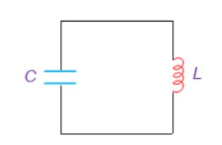
Figure. LC tank circuit
2. Explain the Barkhausen criterion?
Sol:
Conditions that are required to be satisfied to operate the circuit as an oscillator are called as “Barkhausen criterion” for sustained oscillations.
The Barkhausen criterion states that:
• The loop gain is equal to unity in absolute magnitude, that is, | β A | = 1 and
• The phase shift around the loop is zero or an integer multiple of 2π: ∠ β A = 2 π n, n ∈ 0, 1, 2,….
The product β A is called the “loop gain”.
3. Explain the advantage of the RC phase shift oscillator?
Sol:
In an RC Oscillator circuit, the input is shifted 180o through the feedback circuit returning the signal out-of-phase and 180o through an inverting amplifier stage to produces the required positive feedback.
This then gives us “180o + 180o = 360o” of phase shift which is effectively the same as 0o, thereby giving us the required positive feedback.
4. Explain the working of the RC phase shift oscillator?
Sol:
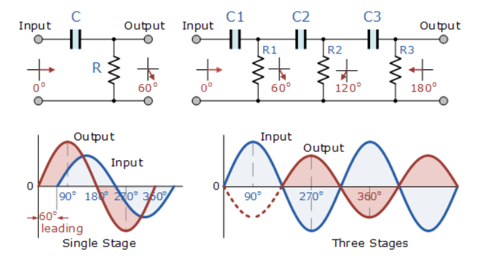
Figure 3. Single-stage and multi-stage phase shift oscillator
The circuit on the left shows a single resistor-capacitor network whose output voltage “leads” the input voltage by some angle less than 90o.
In a pure or ideal single-pole RC network. It would produce a maximum phase shift of exactly 90o, and because 180o of phase shift is required for oscillation, at least two single-poles networks must be used within an RC oscillator design.
However, in reality, it is difficult to obtain exactly 90o of phase shift for each RC stage so we must therefore use more RC stages cascaded together to obtain the required value at the oscillation frequency.
The amount of actual phase shift in the circuit depends upon the values of the resistor (R) and the capacitor (C), at the chosen frequency of oscillations with the phase angle ( φ ) being given as:
Xc = 1/2π fc R=R
Z = [ R 2 + Xc 2 ] ½
Ø = tan -1 Xc /R.
5. Explain the advantage of the Wein Bridge oscillator?
Sol:
Wien bridge oscillator is an audio frequency sine wave oscillator of high stability and simplicity. The feedback signal in this circuit is connected to the non-inverting input terminal so that the op-amp is working as a non-inverting amplifier.
The feedback network does not provide any phase shift. The circuit can be viewed as a Wien bridge with a series combination of R1 and C1 in one arm and a parallel combination of R2 and C2 in the adjoining arm. Resistors R3 and R4 are connected in the remaining two arms.
The condition of zero phase shift around the circuit is achieved by balancing the bridge. The series and parallel combination of RC networks form a lead-lag circuit.
6. Explain the working of the Wein bridge oscillator?
Sol:
At high frequencies, the reactance of capacitor C1 and C2 approaches zero. This causes C1 and C2 to appear short. Here, capacitor C2 shorts the resistor R2. Hence, the output voltage Vo will be zero since the output is taken across R2 and C2 combination. So, at high frequencies, the circuit acts as a 'lag circuit'.
At low frequencies, both capacitors act as open because the capacitor offers very high reactance. Again, the output voltage will be zero because the input signal is dropped across the R1 and C1 combination. Here, the circuit acts like a 'lead circuit'.
But at one particular frequency between the two extremes, the output voltage reaches the maximum value. At this frequency only, the resistance value becomes equal to capacitive reactance and gives maximum output. Hence, this frequency is known as the oscillating frequency (f).
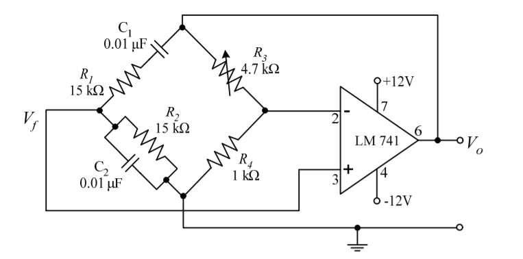
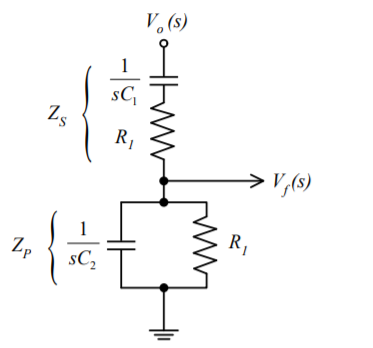
Figure 4. Wein bridge oscillator
Consider the feedback circuit, on applying voltage divider rule
Vf(s) = Vo(s) x Zp(s)/ Zp(s) + Zs(s)
Zs(s) = R1 + 1/sC1 and Zp(s) = R2|| 1/sC2
Let R1=R2=R and C1=C2=C.
On solving
β = Vf(s)/ Vo(s) = RsC /(RsC) 2 + 3RsC + 1 ---------------------------(1)
Since the op-amp is operated in the non-inverting configuration the voltage gain
Av = Vo(s)/ Vf(s) = 1 + R3/R4 -------------------(2)
Applying the condition for sustained oscillations, = Av β =1
RsC /(RsC) 2 + 3RsC + 1. 1 + R3/R4
S=jw
(1 + R3/R4) ( jwRC/ - R2 C2 w2 + 3 jwRC + 1) =1
Jw RC (1 + R3/R4)= (- R2 C2 w2 + 3 jwRC + 1)
Jw[(1 + R3/R4)RC – 3RC] = 1- R2 C2 w2
To obtain the frequency of oscillation equate the real part to zero
1- R2 C2 w2 = 0
w = 1/RC
f = 1/ 2 π RC
To obtain the condition for gain at the frequency of oscillation equate the imaginary part to zero.
Jw[(1 + R3/R4)RC – 3RC] = 0
jw[(1 + R3/R4)RC= jw3RC
[(1 + R3/R4) =3
R3/R4 =2
Therefore R3 = 2 R4 is the required condition.
7. Explain the working of the Hartley oscillator?
Sol:
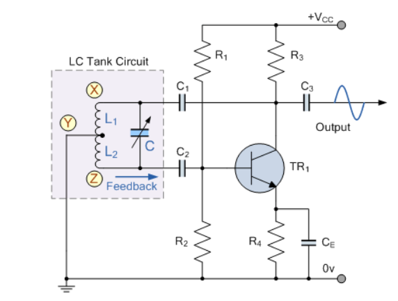
Figure 5. Hartley Oscillator
When the circuit is oscillating, the voltage at point X (collector), relative to point Y (emitter), is 180o out-of-phase with the voltage at point Z (base) relative to point Y.
At the frequency of oscillation, the impedance of the Collector load is resistive and an increase in Base voltage causes a decrease in the Collector voltage.
Thus, there is a 180o phase change in the voltage between the Base and Collector and this along with the original 180o phase shift in the feedback loop provides the correct phase relationship of positive feedback for oscillations to be maintained.
The amount of feedback depends upon the position of the “tapping point” of the inductor. If this is moved nearer to the collector the amount of feedback is increased, but the output taken between the Collector and earth is reduced and vice versa.
Resistors, R1 and R2 provide the usual stabilizing DC bias for the transistor in the normal manner while the capacitors act as DC-blocking capacitors.
In this Hartley Oscillator circuit, the DC Collector current flows through part of the coil, and for this reason the circuit is said to be “Series-fed” with the frequency of oscillation of the Hartley Oscillator being given as.
f=1/2π√ LTC
Where LT = L1 +L2 + 2M
8. Explain the working of Colpitts oscillator?
Sol:
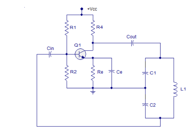
Figure 9. Colpitts oscillator
Resistors R1 and R2 work as voltage divider biasing to the transistor. Resistor R4 limits the collector current of the transistor.
Cin is the input DC decoupling capacitor while Cout is the output decoupling capacitor.
Re is the emitter resistor and it's meant for thermal stability. Ce is the emitter by-pass capacitor.
The job of the emitter by-pass capacitor is to by-pass the amplified AC signals from dropping across Re. The emitter by-pass capacitor is not there, the amplified AC signal will drop across Re and it will alter the DC biasing conditions of the transistor and the result will be reduced gain.
Capacitors C1, C2, and inductor L1 form the tank circuit. Feedback to the base of the transistor is taken from the junction of capacitor C2 and inductor L1 in the tank circuit.
When the power supply is switched ON, capacitors C1 and C2 starts charging. When they are fully charged they start discharging through the inductor L1. When the capacitors are fully discharged, the electrostatic energy stored in the capacitors gets transferred to the inductor as magnetic flux.
The inductor starts discharging and capacitors get charged again. This transfer of energy back and forth between capacitors and inductors is the basis of oscillation.
The voltage across C2 is phase opposite to that of the voltage across the C1 and it is the voltage across C2 that is fed back to the transistor. The feedback signal at the base of the transistor appears in the amplified form across the collector and emitter of the transistor.
The energy lost in the tank circuit is compensated by the transistor and the oscillations are sustained.
The tank circuit produces a 180° phase shift and the transistor itself produces another 180° phase shift. That means the input and output are in phase and it is a necessary condition of positive feedback for maintaining sustained oscillations.
The frequency of oscillations of the Colpitts oscillator can be determined using the equation below.
f = 1/ 2π√LC
Where L is the inductance of the inductor in the tank circuit and C is the effective capacitance of the capacitors in the tank circuit.
9. Determine the frequency of the oscillators in the figure. Assume there is negligible loading in the feedback circuit and Q >10.
Find the frequency of the oscillator is loaded to a point where Q drops to 8.
Sol:
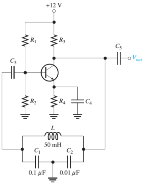
CT = C1C2/ C1 + C2 = (0.1 μF) (0.01μF) / 0.11 μF = 0.0091μF
Fr = 1/2π√LCT = 1/2π√(50mH)(0.0091μF) = 7.46kHz
Fr = 1/2π√LCT √ Q 2/ Q 2 + 1 = 7.46 x 0.9923 = 7.40 kHz
10. Explain non-sinusoidal oscillators?
Sol:
Oscillators that produce output that have square, rectangular, or sawtooth waveform or have an output which is of pulse shape are called Non- Sinusoidal Oscillators.
It is a circuit in which voltage or current changes abruptly from one value to another and which continues to oscillate between these two values as long as dc power is supplied to it.
These oscillators are classified as :
1. Sawtooth Generators
2. Blocking Oscillators
3. Multivibrators
Unit 3
Oscillators
- Explain the concept of oscillators?
Sol:
An oscillator is a circuit that produces a continuous, repeated, alternating waveform without any input. Oscillators convert unidirectional current flow from a DC source into an alternating waveform which is of the desired frequency, as decided by its circuit components.
The basic principle behind the working of oscillators can be understood by analyzing the behaviour of an LC tank circuit shown in Figure below, which employs an inductor L and a completely pre-charged capacitor C as its components.
Here the capacitor starts to discharge via the inductor, which results in the conversion of its electrical energy into the electromagnetic field, which can be stored in the inductor. Once the capacitor discharges completely, there will be no current flow in the circuit.
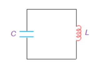
Figure. LC tank circuit
2. Explain the Barkhausen criterion?
Sol:
Conditions that are required to be satisfied to operate the circuit as an oscillator are called as “Barkhausen criterion” for sustained oscillations.
The Barkhausen criterion states that:
• The loop gain is equal to unity in absolute magnitude, that is, | β A | = 1 and
• The phase shift around the loop is zero or an integer multiple of 2π: ∠ β A = 2 π n, n ∈ 0, 1, 2,….
The product β A is called the “loop gain”.
3. Explain the advantage of the RC phase shift oscillator?
Sol:
In an RC Oscillator circuit, the input is shifted 180o through the feedback circuit returning the signal out-of-phase and 180o through an inverting amplifier stage to produces the required positive feedback.
This then gives us “180o + 180o = 360o” of phase shift which is effectively the same as 0o, thereby giving us the required positive feedback.
4. Explain the working of the RC phase shift oscillator?
Sol:
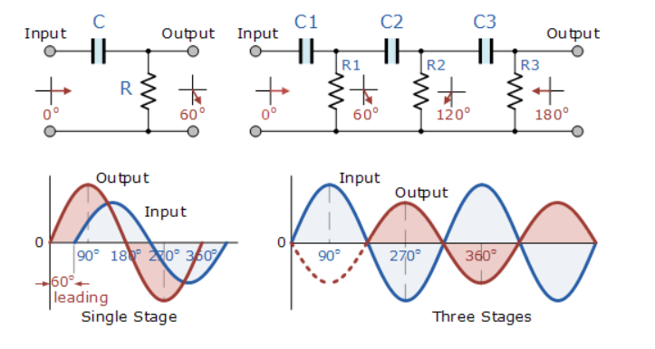
Figure 3. Single-stage and multi-stage phase shift oscillator
The circuit on the left shows a single resistor-capacitor network whose output voltage “leads” the input voltage by some angle less than 90o.
In a pure or ideal single-pole RC network. It would produce a maximum phase shift of exactly 90o, and because 180o of phase shift is required for oscillation, at least two single-poles networks must be used within an RC oscillator design.
However, in reality, it is difficult to obtain exactly 90o of phase shift for each RC stage so we must therefore use more RC stages cascaded together to obtain the required value at the oscillation frequency.
The amount of actual phase shift in the circuit depends upon the values of the resistor (R) and the capacitor (C), at the chosen frequency of oscillations with the phase angle ( φ ) being given as:
Xc = 1/2π fc R=R
Z = [ R 2 + Xc 2 ] ½
Ø = tan -1 Xc /R.
5. Explain the advantage of the Wein Bridge oscillator?
Sol:
Wien bridge oscillator is an audio frequency sine wave oscillator of high stability and simplicity. The feedback signal in this circuit is connected to the non-inverting input terminal so that the op-amp is working as a non-inverting amplifier.
The feedback network does not provide any phase shift. The circuit can be viewed as a Wien bridge with a series combination of R1 and C1 in one arm and a parallel combination of R2 and C2 in the adjoining arm. Resistors R3 and R4 are connected in the remaining two arms.
The condition of zero phase shift around the circuit is achieved by balancing the bridge. The series and parallel combination of RC networks form a lead-lag circuit.
6. Explain the working of the Wein bridge oscillator?
Sol:
At high frequencies, the reactance of capacitor C1 and C2 approaches zero. This causes C1 and C2 to appear short. Here, capacitor C2 shorts the resistor R2. Hence, the output voltage Vo will be zero since the output is taken across R2 and C2 combination. So, at high frequencies, the circuit acts as a 'lag circuit'.
At low frequencies, both capacitors act as open because the capacitor offers very high reactance. Again, the output voltage will be zero because the input signal is dropped across the R1 and C1 combination. Here, the circuit acts like a 'lead circuit'.
But at one particular frequency between the two extremes, the output voltage reaches the maximum value. At this frequency only, the resistance value becomes equal to capacitive reactance and gives maximum output. Hence, this frequency is known as the oscillating frequency (f).
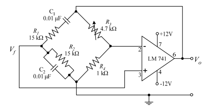
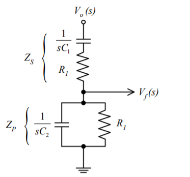
Figure 4. Wein bridge oscillator
Consider the feedback circuit, on applying voltage divider rule
Vf(s) = Vo(s) x Zp(s)/ Zp(s) + Zs(s)
Zs(s) = R1 + 1/sC1 and Zp(s) = R2|| 1/sC2
Let R1=R2=R and C1=C2=C.
On solving
β = Vf(s)/ Vo(s) = RsC /(RsC) 2 + 3RsC + 1 ---------------------------(1)
Since the op-amp is operated in the non-inverting configuration the voltage gain
Av = Vo(s)/ Vf(s) = 1 + R3/R4 -------------------(2)
Applying the condition for sustained oscillations, = Av β =1
RsC /(RsC) 2 + 3RsC + 1. 1 + R3/R4
S=jw
(1 + R3/R4) ( jwRC/ - R2 C2 w2 + 3 jwRC + 1) =1
Jw RC (1 + R3/R4)= (- R2 C2 w2 + 3 jwRC + 1)
Jw[(1 + R3/R4)RC – 3RC] = 1- R2 C2 w2
To obtain the frequency of oscillation equate the real part to zero
1- R2 C2 w2 = 0
w = 1/RC
f = 1/ 2 π RC
To obtain the condition for gain at the frequency of oscillation equate the imaginary part to zero.
Jw[(1 + R3/R4)RC – 3RC] = 0
jw[(1 + R3/R4)RC= jw3RC
[(1 + R3/R4) =3
R3/R4 =2
Therefore R3 = 2 R4 is the required condition.
7. Explain the working of the Hartley oscillator?
Sol:
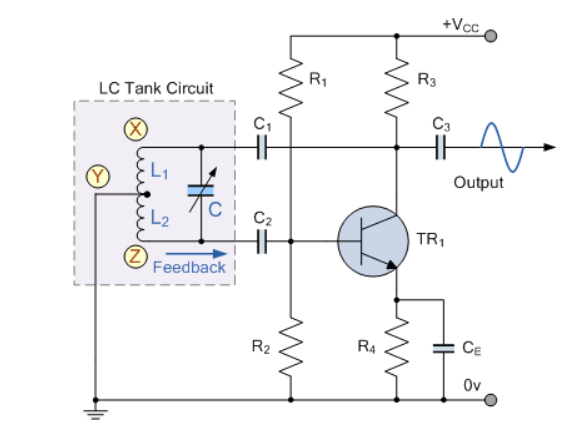
Figure 5. Hartley Oscillator
When the circuit is oscillating, the voltage at point X (collector), relative to point Y (emitter), is 180o out-of-phase with the voltage at point Z (base) relative to point Y.
At the frequency of oscillation, the impedance of the Collector load is resistive and an increase in Base voltage causes a decrease in the Collector voltage.
Thus, there is a 180o phase change in the voltage between the Base and Collector and this along with the original 180o phase shift in the feedback loop provides the correct phase relationship of positive feedback for oscillations to be maintained.
The amount of feedback depends upon the position of the “tapping point” of the inductor. If this is moved nearer to the collector the amount of feedback is increased, but the output taken between the Collector and earth is reduced and vice versa.
Resistors, R1 and R2 provide the usual stabilizing DC bias for the transistor in the normal manner while the capacitors act as DC-blocking capacitors.
In this Hartley Oscillator circuit, the DC Collector current flows through part of the coil, and for this reason the circuit is said to be “Series-fed” with the frequency of oscillation of the Hartley Oscillator being given as.
f=1/2π√ LTC
Where LT = L1 +L2 + 2M
8. Explain the working of Colpitts oscillator?
Sol:
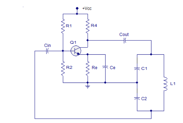
Figure 9. Colpitts oscillator
Resistors R1 and R2 work as voltage divider biasing to the transistor. Resistor R4 limits the collector current of the transistor.
Cin is the input DC decoupling capacitor while Cout is the output decoupling capacitor.
Re is the emitter resistor and it's meant for thermal stability. Ce is the emitter by-pass capacitor.
The job of the emitter by-pass capacitor is to by-pass the amplified AC signals from dropping across Re. The emitter by-pass capacitor is not there, the amplified AC signal will drop across Re and it will alter the DC biasing conditions of the transistor and the result will be reduced gain.
Capacitors C1, C2, and inductor L1 form the tank circuit. Feedback to the base of the transistor is taken from the junction of capacitor C2 and inductor L1 in the tank circuit.
When the power supply is switched ON, capacitors C1 and C2 starts charging. When they are fully charged they start discharging through the inductor L1. When the capacitors are fully discharged, the electrostatic energy stored in the capacitors gets transferred to the inductor as magnetic flux.
The inductor starts discharging and capacitors get charged again. This transfer of energy back and forth between capacitors and inductors is the basis of oscillation.
The voltage across C2 is phase opposite to that of the voltage across the C1 and it is the voltage across C2 that is fed back to the transistor. The feedback signal at the base of the transistor appears in the amplified form across the collector and emitter of the transistor.
The energy lost in the tank circuit is compensated by the transistor and the oscillations are sustained.
The tank circuit produces a 180° phase shift and the transistor itself produces another 180° phase shift. That means the input and output are in phase and it is a necessary condition of positive feedback for maintaining sustained oscillations.
The frequency of oscillations of the Colpitts oscillator can be determined using the equation below.
f = 1/ 2π√LC
Where L is the inductance of the inductor in the tank circuit and C is the effective capacitance of the capacitors in the tank circuit.
9. Determine the frequency of the oscillators in the figure. Assume there is negligible loading in the feedback circuit and Q >10.
Find the frequency of the oscillator is loaded to a point where Q drops to 8.
Sol:
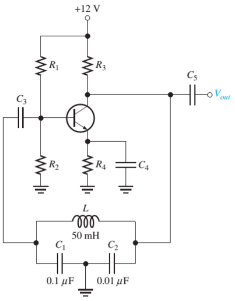
CT = C1C2/ C1 + C2 = (0.1 μF) (0.01μF) / 0.11 μF = 0.0091μF
Fr = 1/2π√LCT = 1/2π√(50mH)(0.0091μF) = 7.46kHz
Fr = 1/2π√LCT √ Q 2/ Q 2 + 1 = 7.46 x 0.9923 = 7.40 kHz
10. Explain non-sinusoidal oscillators?
Sol:
Oscillators that produce output that have square, rectangular, or sawtooth waveform or have an output which is of pulse shape are called Non- Sinusoidal Oscillators.
It is a circuit in which voltage or current changes abruptly from one value to another and which continues to oscillate between these two values as long as dc power is supplied to it.
These oscillators are classified as :
1. Sawtooth Generators
2. Blocking Oscillators
3. Multivibrators