UNIT-III
Probability and Random Process
Q 1. Calculate the thermal noise power available from any resistor at room temperature (290K) for a bandwidth of 1Mhz. Calculate also the corresponding noise voltage given that R = 50 Ω.
Pn = 1.38 x 10 -23 x 290 x 10 6
= 4 x 10 -15.
En2 = 4 x 50 x 1.38 x 10 -23 x 290
= 0.895 µ V
Q1) Suppose you draw two cards from a deck and you win if you get a jack followed by an ace (without replacement). What is the probability of winning, given we know that you got a jack in the first turn?
Let event A be getting a jack in the first turn
Let event B be getting an ace in the second turn.
We need to find P(B/A)
P(A) = 4/52
P(B) = 4/51 {no replacement}
P(A and B) = 4/52*4/51= 0.006
P(B/A) = P(A and B)/ P(A) = 0.006/0.077 = 0.078
Here we are determining the probabilities when we know some conditions instead of calculating random probabilities
Q2) Explain Gaussian white noise with PSD.
White noise is often used to model the thermal noise in electronic systems. By definition, the random process X(t) is called white noise if SX(f) is constant for all frequencies. By convention, the constant is usually denoted by N0/2
The random process X(t) is called a white noise process if
SX(f)=N0/2, for all f.
Before going any further, let's calculate the expected power in X(t). We have
E[X(t)2]=∫SX(f)df=∫ N0/2df=∞
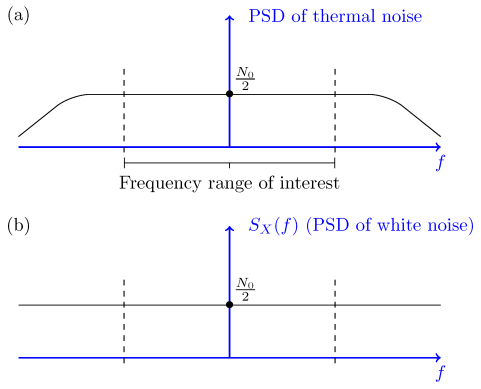
Thus, white noise, as defined above, has infinite power! In reality, white noise is in fact an approximation to the noise that is observed in real systems. To better understand the idea, consider the PSDs shown in Figure

Figure 1- Part (a): PSD of thermal noise; Part (b) PSD of white noise.
Part (a) in the figure shows what the real PSD of a thermal noise and the PSD of the white noise is shown in Part (b) are approximately the same.
The thermal noise in electronic systems is usually modeled as a white Gaussian noise process. It is usually assumed that it has zero mean μX=0 and is Gaussian.
The random process X(t) is called a white Gaussian noise process if X(t) is a stationary Gaussian random process with zero mean, μX=0, and flat power spectral density,
SX(f)=N0/2, for all f
Since the PSD of a white noise process is given by SX(f)=N0/2, its autocorrelation function is
RX(τ)=F−1{N0/2}=N0/2δ(τ),
Where δ(τ) is the dirac delta function
δ(x)= 0, x=0 otherwise 1 for x=1
Q3) Let X(t) be a white Gaussian noise process that is input to an LTI system with transfer function
|H(f)|={21<|f|<20 otherwise
If Y(t) is the output, find P (Y (1) <N0).
Solution
Since X(t)X(t) is a zero-mean Gaussian process, Y(t) is also a zero-mean Gaussian process. SY(f) is given by

Therefore,

= 4 .
.
Thus,
Y
To find P(Y(1)<

= Φ 
Q4) Define Thermal noise.
Thermal noise is the electronic noise generated by thermal agitation of charge carriers inside an electrical conductor in equilibrium, which happens regardless of any applied voltage.
Movement of electrons will form kinetic energy in the conductor related to temperature in the conductor.
When the temperature increases the movement of electrons increases and current flows through the conductor.
Current flows due to free electrons which create noise voltage n(t).
Noise voltage is influenced by temperature hence it is called thermal noise.
Q5) Write and explain types of FM noises.
Shot Noise
Shot noise arises because the current consists of a vast number of discrete charges.
The continuous flow of these discrete pulses gives rise to almost white noise. There is a cut-off frequency by the time it takes for the electron or other charge carrier to travel through the conductor.
Unlike thermal noise, this noise is dependent upon the current flowing and has no relationship to the temperature at which the system is operating.
Shot noise is more apparent in devices such as PN junctions. The electrons are transmitted randomly and independently of each other.
Partition Noise
When the circuit is to divide in between two or more paths then the noise generated is known as Partition noise. The reason for this generation is random fluctuation in the division.
Flicker Noise
Flicker noise or modulation noise is the one appearing in transistors operating at low audio frequencies. Flicker noise is proportional to the emitter current and junction temperature. However, this noise is inversely proportional to the frequency.
Burst Noise
Burst noise consists of step-like transitions suddenly between two or more discrete voltages or current levels.
Each shift in offset voltage or current lasts for millisecond to seconds. It is also known as popcorn noise because of the popping or crackling sound it produces in audio circuits.
Avalanche Noise
Avalanche noise is the noise produced when a junction diode is operated at the onset of avalanche break down, a semiconductor junction phenomenon in which the carriers having high voltage gradient develop sufficient energy to dislodge additional carriers through physical impact creating ragged current flow.
Q6) Explain average power and autocorrelation function.
White noise plays an important role in modelling of WSS signals. A white noise process W(t) is a random process that has constant power spectral density at all frequencies.
Thus
S w(w) = N0/2 ----------------(1) - ∞<w<∞
Where No is real constant and called the intensity of the white noise. The corresponding autocorrelation is given by
Rw( = N/2
= N/2  (
( where
where  (
( is the Dirac delta.
The average power of white noise
P wg = E W 2 = 1/2π dw -> ∞
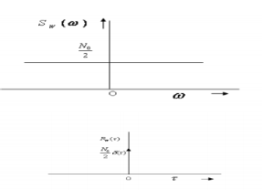
The autocorrelation function and the PSD of white noise process is shown in Figure.

Fig.2 : White noise
Q7) Explain pre-emphasis and de-emphasis circuit with the help of diagram.
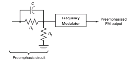
- Pre-emphasis: The noise suppression ability of FM decreases with the increase in the frequencies. Thus, increasing the relative strength or amplitude of the high frequency components of the message signal before modulation is termed as Pre-emphasis. The Fig3 below shows the circuit of pre-emphasis.

Fig3. Pre-emphasis circuit
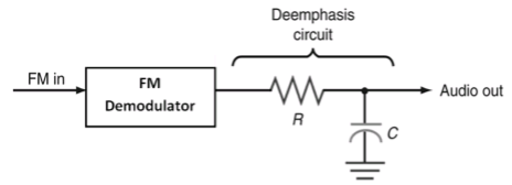
- De-emphasis: In the de-emphasis circuit, by reducing the amplitude level of the received high frequency signal by the same amount as the increase in pre-emphasis is termed as De-emphasis. The Fig4. Below shows the circuit of de-emphasis.

Fig4. De-emphasis circuit
- The pre-emphasis process is done at the transmitter side, while the de-emphasis process is done at the receiver side.
- Thus, a high frequency modulating signal is emphasized or boosted in amplitude in transmitter before modulation. To compensate for this boost, the high frequencies are attenuated or de-emphasized in the receiver after the demodulation has been performed. Due to pre-emphasis and de-emphasis, the S/N ratio at the output of receiver is maintained constant.
- The de-emphasis process ensures that the high frequencies are returned to their original relative level before amplification.
- Pre-emphasis circuit is a high pass filter or differentiator which allows high frequencies to pass, whereas de-emphasis circuit is a low pass filter or integrator which allows only low frequencies to pass.