Unit 3
Antenna Fundamentals and Definition
Q1) Write a short note on antenna pattern?
The radiation pattern or antenna pattern is the graphical representation of the radiation properties of the antenna as a function of space.
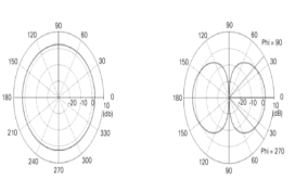
(a):dipole azimuth radiation pattern (b):dipole elevation radiation pattern
Figure 1. Antenna patterns
In discussions of principal plane patterns or even antenna patterns, you will frequently encounter the terms azimuth plane pattern and elevation plane pattern. The term azimuth is commonly found in reference to "the horizontal" whereas the term elevation commonly refers to "the vertical".
The fig.(a) shows horizontal pattern and fig.(b) shows vertical pattern.
Q2) What is half power beam width?
Half power beam width
Definition
The 3 dB, or half power, beamwidth of the antenna is defined as the angular width of the radiation pattern, including beam peak maximum, between points 3 dB down from maximum beam level (beam peak).
Indication of HPBW
When a line is drawn between radiation pattern’s origin and the half power points on the major lobe, on both the sides, the angle between those two vectors is termed as HPBW, half power beam width. This can be well understood with the help of the following diagram.
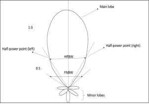
Figure 2 half-power points on the major lobe and HPBW.
Mathematical Expression
The mathematical expression for half power beam width is
Half power Beam Width = 70 λ /D
Where
Units
The unit of HPBW is radians or degrees.
Q3) Explain Radiation resistance?

Q4) Explain reflection co-efficient?
In the context of antennas and feeders, the reflection coefficient is defined as the figure that quantifies how much of an electromagnetic wave is reflected by an impedance discontinuity in the transmission medium. The reflection coefficient is equal to the ratio of the amplitude of the reflected wave to the incident wave.
Calculating reflection coefficient
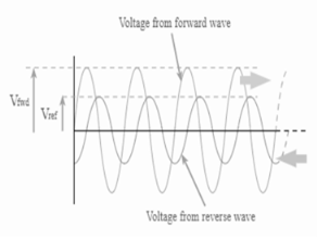
Figure 3. Reflection coefficient
r = 
Where,
r= reflection co-efficient
Vref= = reflected voltage
Vfwd = forward voltage
r = 
Where:
Γ = reflection coefficient
Pref = reflected power
Pfwd = forward power
Q5) What is meant by polarization of an antenna?

| |=|
|=| |
|
 =
= 
 =
= 
| |
| |
| |
|

 =
= 

Q6) Explain the different types of patterns in antenna?
Isotropic Pattern - an antenna pattern defined by uniform radiation in all directions, produced by an isotropic radiator (point source, a non-physical antenna which is the only nondirectional antenna). Directional Pattern - a pattern characterized by more efficient radiation in one direction than another (all physically realizable antennas are directional antennas).
Omnidirectional Pattern - a pattern which is uniform in a given plane.
Principal Plane Patterns - the E-plane and H-plane patterns of a linearly polarized antenna.
E-plane - the plane containing the electric field vector and the direction of maximum radiation.
H-plane - the plane containing the magnetic field vector and the direction of maximum radiation.
Q7) What is beam angle?
Beam Area (or beam solid angle)
In polar two-dimensional coordinates an incremental area dA on the surface of a sphere is the product of the length r dθ in the θ direction (latitude) and r sin θ dφ in the φ direction (longitude), as shown in Fig. Thus,
dA = (r dθ)(r sinθ dφ) = r 2 dΩ (1)
Where dΩ = solid angle expressed in steradians (sr) or square degrees ( ) dΩ = solid angle subtended by the area dA
The beam area or beam solid angle or ΩA of an antenna is given by the integral of the normalized power pattern over a sphere (4π sr)

Q8) Explain beam effeciency?
Beam Efficiency
ΩA = ΩM + Ωm
Beam Efficiency = (Dimensionless)
The ratio of the minor-lobe area (Ωm) to the (total) beam area is called the stray factor. Thus
 = stray factor
It follows that
 +
+  = 1
= 1
Q9) Explain directivity and gain?
Directivity (D)
The directivity D and the gain G are probably the most important parameters of an antenna. The directivity of an antenna is equal to the ratio of the maximum power density P(θ, φ)max (watts/m2 ) to its average value over a sphere as observed in the far field of an antenna. Thus,
D = 
The directivity is a dimensionless ratio ≥1. The average power density over a sphere is given by
P =
= 
= dΩ (W
dΩ (W  )
)
Therefore, the directivity
D =  =
=
And
D = 
This is the diversity from beam area, where Pn(θ, φ) dΩ = P(θ, φ)/P(θ, φ)max = normalized power pattern.
Gain
The gain G of an antenna is an actual or realized quantity which is less than the directivity D due to ohmic losses in the antenna or its radome (if it is enclosed). In transmitting, these losses involve power fed to the antenna which is not radiated but heats the antenna structure. A mismatch in feeding the antenna can also reduce the gain. The ratio of the gain to the directivity is the antenna efficiency factor. Thus, G = kD
Where k= Efficiency factor (0< k< 1), dimensionless
Q10) Explain antenna aperture?
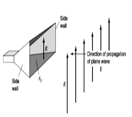
Figure 5. Plane wave incident on electromagnetic horn of physical aperture AP
P = 
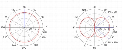
Figure 6. Radiation over beam area
 (Dimensionless) Aperture efficiency
where εap =aperture efficiency.
Q11) Write a short note on radio communication link?
The Friis transmission formula is used in telecommunications engineering, equating the power at the terminals of a receive antenna as the product of power density of the incident wave and the effective aperture of the receiving antenna under idealized conditions given another antenna some distance away transmitting a known amount of power

Pr = Received power, W
Pt = Received power, W
Aet = Effective aperture of transmitting antenna, m2
Aer = Effective aperture of receiving antenna, m2
r = Distance between antennas, m
 = Wavelength, m
The Friis transmission formula is used in telecommunications engineering, equating the power at the terminals of a receive antenna as the product of power density of the incident wave and the effective aperture of the receiving antenna under idealized conditions given another antenna some distance away transmitting a known amount of power.
Friss transmission is given by
 )
)
Q12) Write a note on fields on oscillating dipole?
It is a normal dipole antenna, where the frequency of its operation is half of its wavelength. Hence, it is called as half-wave dipole antenna.
The edge of the dipole has maximum voltage. This voltage is alternating (AC) in nature. At the positive peak of the voltage, the electrons tend to move in one direction and at the negative peak, the electrons move in the other direction. This can be explained by the figures given below.
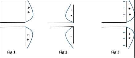
Figure . Haly wave dipole.
The figures given above show the working of a half-wave dipole.
The cumulative effect of this produces a varying field effect which gets radiated in the same pattern produced on it. Hence, the output would be an effective radiation following the cycles of the output voltage pattern. Thus, a half-wave dipole radiates effectively.
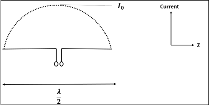
Figure . Current distribution
The above figure shows the current distribution in half wave dipole. The directivity of half wave dipole is 2.15dBi, which is reasonably good. Where, ‘i’ represents the isotropic radiation.